SRI990 - FOXBORO ECKARDT
SRI990 - FOXBORO ECKARDT
SRI990 - FOXBORO ECKARDT

You also want an ePaper? Increase the reach of your titles
YUMPU automatically turns print PDFs into web optimized ePapers that Google loves.
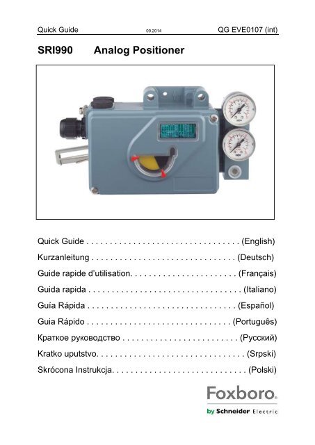
Quick Guide 09.2014 QG EVE0107 (int)<strong>SRI990</strong>Analog PositionerQuick Guide . . . . . . . . . . . . . . . . . . . . . . . . . . . . . . . . . (English)Kurzanleitung . . . . . . . . . . . . . . . . . . . . . . . . . . . . . . . (Deutsch)Guide rapide d’utilisation. . . . . . . . . . . . . . . . . . . . . . . (Français)Guida rapida . . . . . . . . . . . . . . . . . . . . . . . . . . . . . . . . . (Italiano)Guía Rápida . . . . . . . . . . . . . . . . . . . . . . . . . . . . . . . . (Español)Guia Rápido . . . . . . . . . . . . . . . . . . . . . . . . . . . . . . . (Português)Краткое руководство . . . . . . . . . . . . . . . . . . . . . . . . . (Русский)Kratko uputstvo. . . . . . . . . . . . . . . . . . . . . . . . . . . . . . . . (Srpski)Skrócona Instrukcja. . . . . . . . . . . . . . . . . . . . . . . . . . . . . (Polski)
<strong>SRI990</strong>QG EVE0107 (int)
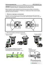
Quick Guide 09.2014 QG EVE0107 (en)<strong>SRI990</strong> Analog PositionerThese instructions are to be used as a guide for quick start-up. For more detailed information pleaserefer to the standard documents “Master Instructions” and “Product Specification Sheet”. These canbe found on our Website www.foxboro-eckardt.com .1. Mounting to actuatorsDuring operation the flat side of the spindle 9 on the back of the positioner must always point towardsthe arrow 26. The working angle around this position is ± 45°1.1 Mounting to linear actuatorsNAMUR mounting Direct mounting NAMUR mounting- left hand - - right hand -Feedback lever for linear actuators:The carrier bolt B is in the slot of the feedback lever Aand the compensating spring F touches the carrier bolt.Carrier bolt B:1 threaded sleeve2 Stud3 coupling piece
2 <strong>SRI990</strong> QG EVE0107 (en)1.2 Mounting to rotary actuators• Do not tighten grub screw 4 against the thread ofspindle 9 !• When in use the flat side of the spindle 9 must move( 0 ↔ 100%) in front of the arrow 26.• When the product temperature rises, the drive shaft1 increases in length. Therefore, the rotary adaptor 3must be mounted so that approx. 1 mm (0.04 in.) ofclearance results between the drive shaft 1 and therotary adaptor 3. This is achieved by placing anappropriate number of washers 5, on the feedbackspindle 9, before attaching the rotary adaptor. Twowashers should result in a clearance of 1 mmActuator, left turningActuator, right turning2 Pneumatic connectionsAir supply (s): 1,4 to 6 bar (but not more than the max. pressure of actuator), free of oil, dust and water !Single acting, direct mounting Single acting Double actings air supply y1, y2 pneumatic outputs (--) closed
QG EVE0107 (en) <strong>SRI990</strong> 33. Electrical connectionsThe safety requirements of document EX EVE0001 as well as the requirements of PSS EVE0107 andMI EVE0107 for <strong>SRI990</strong> must be observed!3.3 Limit switch<strong>SRI990</strong>-xxxT or UTwo-wire proximity sensors,Acc. to DIN 19234 or NAMURSupply voltage DC 8 VSwitching amplifier withintrinsically safe control circuitSwitching amplifier withintrinsically safe control circuit<strong>SRI990</strong>-xxxV3.1 Setpoint3.2 Positionfeedback 4-20 mA(<strong>SRI990</strong>-xxQ)Warning: For connection of microswitches please refer to MI (MasterInstruction) and respect the safetyrequirements described in documentEX EVE0001.Input 4 to 20 mAAnalog output 4 to 20 mA,Two-wire system,Supply voltage DC 8 to 48 V*4 START UP (setting by means of local switches and potentiometers)4.1 Initial settingAfter mounting the positioner on theactuator, air and electrical input connected,proceed as follow.First all switches must be in position I. Thisis the setting for Input signal “4 to 20 mA”and “Left mounted” (counter clockwiserotation).* For intrinsically safe circuits please refer to certificate / data label for max. operating voltages etc.
4 <strong>SRI990</strong> QG EVE0107 (en)4.2 Configuration direction of rotation of feedback shaftDefined as direction of rotation of feedbackshaft from the start to the end position, lookingat the positioner from the front. Switch 1+2 to“R” if necessary.R= right turn (clockwise) L= left turn (counter cw)4.3 Setting of zero, span and gaina) Apply 4 mA to Input.b) Turn potentiometer P3 for zero point (ZERO) untilactuator just begins to move from its end position.Rotation P3 to the right: zero point is increasedRotation P3 to the left: zero point is reducedc) Apply 20 mA to Inputd) Turn potentiometer P2 for span (S) until actuatorexactly reaches its end position.Rotation P2 to the right: span is increasedRotation P2 to the left: span is reducede) The loop amplification of the positioner is set viapotentiometer P4. Trim the gain so that the actuatorwill not swing at constant given input value.f) Re-check zero and span settings.5 Setting and Start Up of position transmitter 4-20mAThe electronic connection of the position transmitter must beassured. Both LED’s are then light up.Adjusting the start of the measuring range (4mA)a) Move the actuator to the starting position.b) Press push button S1 „Config Output 4mA“ longer than2 seconds. During this time LED 1 lights up. After 2seconds both LED’s are light up again, the value for 4mAis stored.Adjusting the end of the measuring range (20mA)a) Move the actuator to the end position.b) Press push button S2 „Config Output 20mA“ longer than 2 seconds. During this time LED 2 lightsup. After 2 seconds both LED’s are light up again, the value for 20mA is stored.
Kurzanleitung 09.2014 QG EVE0107 (de)<strong>SRI990</strong> Analoger StellungsreglerDiese Instruktionen dienen als Anleitung für eine schnelle Inbetriebnahme. Ausführlichere Informationensind in den Dokumenten “Inbetriebnahme- und Wartungsanleitung” und “Typenblatt”, die Sieauch auf unserer Webseite www.foxboro-eckardt.de finden.1. Montage an AntriebAuf der Rückseite des Stellungsreglers ist die Anlenkwelle 9 . Die Anlenkwelle steht richtig, wenn derPfeil 26 auf die Flachstelle der Anlenkwelle zeigt. Der Arbeitsbereich ist dann ± 45 Grad um diesePosition.1.1 Montage an LinearantriebeAnbau nach NAMUR Direktanbau Anbau nach NAMUR- linksseitig - - rechtsseitig -Anlenkhebel bei Linearantrieben:Der Anlenkbolzen B greift in den Schlitz des Anlenkhebels Aein. Die Ausgleichsfeder F liegt am Anlenkbolzen an.Anlenkbolzen B:1 Gewindehülse2 Gewindestift3 Kupplungsstück
QG EVE0107 (de) <strong>SRI990</strong> 33. Elektrische AnschlüsseDie Sicherheitsbestimmungen im Dokument EX EVE0001 sowie die Bestimmungen in PSS EVE0107und MI EVE0107 für <strong>SRI990</strong> müssen beachtet werden.3.3 Grenzwertgeber<strong>SRI990</strong>-xxxT oder UZweidraht-Sensoren,nach DIN 19234 oder NAMURVersorgungsspannung DC 8 VSchaltverstärker miteigensicherem SteuerstromkreisSchaltverstärker miteigensicherem Steuerstromkreis<strong>SRI990</strong>-xxxV3.1 SollwertEingang 4 bis 20 mA3.2 Stellungsrückmeldung4 bis 20 mA(<strong>SRI990</strong>-xxQ)Analog-Ausgang 4 bis 20 mA,Zweidraht-SystemZu versorgen mit DC 8 bis 48 V*Achtung: Beim Anschluss derMikroschalter sind die Hinweise inder MI (Inbetriebnahme- undWartungsanleitung) sowie dieSicherheitsbestimmungen imDokument EX EVE0001 zubeachten.4 INBETRIEBNAHME (Einstellung mit lokalen Schaltern und Potentiometern)4.1 GrundeinstellungNach Anbau an den Antrieb und pneumatischemund elektrischem Anschluss, gehen Sie vor wiefolgt: Zuerst müssen alle Schalter in Position Istehen. Das ist die Einstellung für Eingangssignal“4 bis 20 mA” und “Linksanbau” (Drehrichtung imGegen-Uhrzeigersinn).* Bei Einsatz im Ex-gefährdeten Bereich sind die max. Versorgungsspannungen etc. auf dem Typenschild bzw.Baumusterprüfbescheinigung zu beachten!
2 <strong>SRI990</strong> QG EVE0107 (fr)1.2 Montage sur servomoteurs rotatifs• Ne pas visser la vis 4 contre le filetage de l’axe detraversée 9, mais sur le méplat!• En fonctionnement le méplat de l’axe de traversée 9doit tourner devant la flèche 26.• L’axe du servomoteur 1 s’allonge sous l’effet de lachaleur produite lors du fonctionnement duservomoteur. C’est pourquoi l’adaptateur 3 doit êtremonter de façon à ce qu’il y ait, entre lui et l’axe detransmission 1, un jeu d’environ 1 mm. Ce jeu peutêtre obtenu en ajoutant un nombre approprié derondelles 5 sur l’axe de traversée 9.Servomoteur, sens de rotation anti-horaireServomoteur, sens de rotation horaire2 Raccordements pneumatiquesAir d’alimentation (s) : 1,4 à 6 bar (en respectant la pression de travail maximum du servomoteur) airpropre, déshuilé, sans poussière et eau!Simple effet, montage direct Simple effet Double effets air d’alimentation y1, y2 sorties pneumatiques (--) fermé
QG EVE0107 (fr) <strong>SRI990</strong> 33. Raccordements électriquesLes recommandations de sécurité du document EX EVE0001 ainsi que les recommandations de laPSS EVE0105 et de la MI EVE0105 doivent être observées !3.3 Fins de course<strong>SRI990</strong>-xxxT or UCapteurs inductifs technique deuxfils, selon DIN 19234 ou NAMURTension d’alimentation 8 V CCAmplificateur séparateur avecsécurité intrinsèqueAmplificateur séparateur avecsécurité intrinsèque<strong>SRI990</strong>-xxxV3.1 Signal d’entrée3.2 Recopie deposition 4-20 mA(<strong>SRI990</strong>-xxQ)Attention : Pour le raccordementdes micro-contacts respecter lesrecommandations de la MI(instructions de mise en service) etdu document EX EVE0001.Signal 4-20 mASortie analogique 4-20 mA,Technique deux fils,Tension d’alimentation 8 à 48 V CC*4 Mise en marche du positionneur (au moyen des mirco-switch et potentiomètres)4.1 Réglage initialAprès le montage sur le servomoteur, lesraccordements pneumatiques et électriquesfaits, procéder comme ceci:Au début tous les micro-switch doivent êtreen position I. Cette configuration signifie,signal d’entrée 4-20mA et rotation du levieranti-horaire.* Pour les installations dans des zones á sécurité intrinsèque se reporter aux certificats et aux labels pour les tensions maximad’utilisation.
4 <strong>SRI990</strong> QG EVE0107 (fr)4.2 Configuration du sens de rotation du levier de feedbackLe sens est défini par la rotation du levier de laposition 0% à la position 100% en regardant lepositionneur en face avant.Micro-switch 1+2 sur ”R” si nécessaire.R= right turn (Horaire) L= left turn (Anti-horaire)4.3 Configuration du zéro, course et gaina) Appliquer 4 mA en entrée.b) Tourner le potentiomètre P3 (ZERO) jusqu’à ceque le servomoteur commence à bouger de saposition 0%.Rotation P3 vers la droite: augmenter le point zéroRotation P3 vers la gauche: diminuer le point zéroc) Appliquer 20 mA en entrée.d) Tourner le potentiomètre P2 pour la course (S)jusqu’à ce le servomoteur soit exactement dans saposition finale 100%.Rotation P2 vers la droite: augmenter la courseRotation P2 vers la gauche: diminuer la coursee) Le gain du positionneur est donné par lepotentiomètre P4. Ajuster le gain de façon á avoir unpositionnement stable du servomoteur.f) Contrôler de nouveau les réglages du zéro et de lacourse.5 Réglage et mise en marche du transmetteur de position 4–20 mAUne fois le raccordement électrique du transmetteur deposition réalisé, les deux LED s’allument.Ajuster le départ de la gamme de mesure (4 mA)a) Déplacer le servomoteur en position de départ (0%).b) Appuyer sur le bouton-poussoir S1 « Config Output 4 mA »pendant plus de deux secondes. Pendant ce temps la LED 1s’allument. Après deux secondes, les deux LED s’allument ànouveau, la valeur pour 0% - 4 mA est sauvegardée.Ajuster la fin de la gamme de mesure (20 mA)a) Déplacer le servomoteur en position 100% de la course.b) Appuyer sur le bouton poussoir S2 « Config Output 20mA » pendant plus de deux secondes.Pendant ce temps la LED 2 s’allument. Au bout de deux secondes, les deux LED s’allument ànouveau, la valeur pour 100% - 20mA est sauvegardée.
Guida rapida 09.2014 QG EVE0107 (it)<strong>SRI990</strong> Posizionatore analogicoQueste istruzioni sono un supporto per consentire una guida rapida al montaggio e alla messa inservizio del posizionatore. Per informazioni dettagliate del prodotto fate riferimento alladocumentazione ufficiale ”Master instruction” e ”Product Specification Sheet” disponibili sul sitoInternet www.foxboro-eckardt.com.1. Montaggio sull’attuatoreDurante l’operazione di montaggio il lato smussato del perno 9, sul retro del posizionatore, devesempre essere rivolto verso la freccia 26. L’angolo di lavoro da questa posizione è di ± 45°.1.1 Montaggio su attuatori lineariMontaggio NAMUR Montaggio direct Montaggio NAMUR- lato sinistro - - lato destro -Leva di feedback per attuatori lineari:Il perno B và inserito nella feritoia della leva difeedback A. La molla di compensazione Ftocca il perno..Perno d’accoppiamento B:1 bussola2 perno3 giunto d’accoppiamento
2 <strong>SRI990</strong> QG EVE0107 (it)1.2 Montaggio su attuatori rotativi• Non avvitare il grano sul lato filettato del perno 9 !• Durante il funzionamento, il lato smussato del perno 9 devemuoversi (0 ↔ 100 %) sul lato indicato dalla freccia 26.• Quando la temperatura aumenta, l’albero dell’attuatore 1,per effetto della dilatazione termica, si allunga. L’adattatoreper movimento rotativo 3 deve essere montato in modo dagarantire un gioco di circa 1mm(0.04 in.) tra l’alberodell’attuatore 1 e l’adattatore rotativo 3. Questo si ottieneinfilando un numero appropriato di rondelle 5 nel perno difeedback9, prima di fissare l’adattatore rotativo. Duerondelle dovrebbe essere sufficienti per garantire un gioco di1mm.Attuatore con movimento a sinistraAttuatore con movimento a destra2 Collegamenti pneumaticiAria di alimentazione (s): da 1,4 a 6 bar (ma non maggiore della pressione massima dell’attuatore) esenteda olio particolato e acqua.Singolo effetto, montaggio diretto Singolo effetto Doppio effettos aria di alimentazione y1, y2 uscite pneumatiche (--) chiuso
QG EVE0107 (it) <strong>SRI990</strong> 33. Collegamenti elettriciLe raccomandazioni di sicurezza del documento EX EVE001 cosi come le raccomandazioni della PSSEVE0107 e della MI EVE0107 devono essere rispettate.3.3 Fine corsa<strong>SRI990</strong>-xxxT or USensori di prossimità a due filiin accordo con la DIN 19234 oNAMURTensione d’alimentazione DC 8 VAmplificatore con circuito diseparazione a sicurezza intrinsecaAmplificatore con circuito diseparazione a sicurezza intrinseca3.1 Signale di comando(Setpoint)3.2 trasmettitore diposizione 4-20 mA(<strong>SRI990</strong>-xxQ)<strong>SRI990</strong>-xxxVAttenzione : Il collegamento deimicro-switch deve essere fattorispettando le raccomandazioni dellaMI (montaggio e servizio) e leraccomandazioni di sicurezza deldocumento EX EVE0001.Signale 4-20 mAUscita analogica 4-20 mA,Tecnica due fili,Tensione d’alimentazione DC 8 à 48 V*4 Messa in servizio (impostazione tramite i switch locali e potenziometri)4.1 Regolazione inizialeDopo aver provveduto al montaggio delposizionatore sull’attuatore e al collegamentoelettrico e pneumatico, procedete nel seguentemodo: All’inizio tutti i switch debbono essere sullaposizione I. Questo significa una configurazioneper un segnale d’ingresso 4-20mA e unarotazione della leva nel senso anti-orario.* Per le installazioni in zona a sicurezza intrinseca, riportarci ai certificati e alle targhette segnaletiche per le tensione massimed’utilizzo.
4 <strong>SRI990</strong> QG EVE0107 (it)4.2 Configurazione del senso di rotazione della leva di feedbackIl senso è definito dalla rotazione della levadella posizione 0% alla posizione 100%guardando il posizionatore dalla faccia avanti.Switch 1+2 su ”R” se necessarioR=right turn (orario) L=left turn (anti-orario)4.3 Configurazione dello zero, corsa e guadagnoa) Dare 4mA in ingressob) Girare il potenziometro P3 (ZERO) fino a faremuovere l’attuatore della sua posizione 0%.Girare P3 a destra: aumento del punto zeroGirare P3 a sinistra: riduzione del punto zeroc) Dare 20mA in ingressod) Girare il potenziometro P2 (S) per la corsa fino aposizionare l’attuatore nella sua esatta posizione100%Girare P2 a destra: aumento la corsaGirare P2 a sinistra: riduzione la corsae) Il guadagno del posizionatore è dato dalpotenziometro P4. Aggiustare il guadagno per avereun posizionamento stabile dell’attuatore.f) Controllare di nuovo le regolazioni fatte del zero edella corsa.5 Messa in servizio del trasmettitore di posizione 4-20mAL’elettronica deve essere collegata alla sorgente di tensione.I due LED devono essere accesi.Regolazione del 4mAa) Portare l’attuatore nella posizione di partenza.b) Premere il tasto S1 „Config Output 4mA“ per 2 secondi. IlLED 1 si accende. Dopo 2 secondi, i due LED sononuovamente accesi e il valore di 4mA è memorizzato.Regolazione del 20mAa) Portare l’attuatore in posizione finale.b) Premere il tasto S2 „Config Output 20mA“ per 2 secondi. Il LED 2 si accende. Dopo le 2 secondi, idue LED sono nuovamente accesi e il valore di 20mA è memorizzato.
Guía rápida 09.2014 QG EVE0107 (es)<strong>SRI990</strong> Posicionador analógicoEstas instrucciones deben usarse como guía para una rápida puesta en servicio. Para unainformación más detallada, véanse los documentos estandar ”Master Instructions” y ”ProductSpecification Sheet”. Estos documentos se encuentran en nuestra Web www.foxboro-eckardt.com.1. Montaje en actuadoresDurante la operación, el lado plano del eje 9 de la parte trasera del posicionador, debe apuntarsiempre hacia la flecha 26. El ángulo de trabajo alrededor de esta posición es ± 45°.1.1 Montaje en actuadores linealesMontaje NAMUR Montaje directo Montaje NAMUR- a la izquierda - - a la derecha -Palanca de realimentación para actuadores lineales:El perno guía B se situa en la ranura de la palanca derealimentación A , y el muelle de compensación F , tocaal perno guía.Perno guía B:1 manguito roscado2 taco3 pieza de acoplamiento
QG EVE0107 (es) <strong>SRI990</strong> 33. Conexiones eléctricas¡ Para el <strong>SRI990</strong> deben observarse los requisitos de seguridad del documento EX EVE0001, asícomo también los requisitos contenidos en las PSS EVE0107 y MI EVE0107 !3.3 Limite de carrera<strong>SRI990</strong>-xxxT ó USensores de proximidad de doshilos de acuerdo con DIN 19234 óNAMURAlimentación 8 V CCAmplificador de commutación concircuito de seguridad intrínsecaAmplificador de commutación concircuito de seguridad intrínseca<strong>SRI990</strong>-xxxV3.2 3.1 Signal Punto de d’entréeconsigna3.2 Transmisor deposición 4 a 20 mA(<strong>SRI990</strong>-xxQ)Atención: Para la conexión demicrointerruptores, véase la MI(Master Instruction) y obsérvenselos requisitos de seguridad descritosen el documento EX EVE0001.Signal 4-20 mAEntrada 4 a 20 mASalida analógica 4 a 20 mA,sistema a dos hilos,Alimentación 8 a 48 V CC*4 PUESTA EN SERVICIO (Sintonizado mediante los conmutadores y potenciómetros locales)4.1 Sintonizado inicialTras el montaje del posicionador en el actuador,conectado el aire de alimentación y realizadas lasconexiones eléctricas, procédase como sigue: Alprincipio todos los conmutadores deben estar en laposición I. Este es el sintonizado para una señal deentrada ”4 a 20 mA” y un ”montaje a la izquierda”(sentido de rotación anti-horario).* Para los circuitos de seguridad intrínseca, véanse los valores máximos de tensión, etc. en el Certificado y/o Placa de Datosdel Instrumento.
4 <strong>SRI990</strong> QG EVE0107 (es)4.2 Configurar la dirección de rotación del eje de realimentaciónDefinida como dirección de rotación del eje derealimentación desde la posición inicial a lafinal, mirando al posicionador de frente.Conmutar 1+2 a ”R” si es necesario.R = giro a la derecha (horario)L = giro a la izquierda (anti-horario)4.3 Sintonizado del cero, amplitud (span) y gananciaa) Aplicar 4 mA a la entrada.b) Mover el potenciómetro de cero P3 (ZERO) hastaque el actuador empiece a moverse desde suposición inicial.Rotación de P3 a la derecha: aumenta el punto de ceroRotación de P3 a la izquierda: disminuye el punto de ceroc) Aplicar 20 mA a la entradad) Mover el potenciómetro de amplitud P2 (S) hastaque el actuador alcance exactamente la posición final.Rotación de P2 a la derecha: aumenta la amplitudRotación de P2 a la izquierda: disminuye la amplitude) La amplificación del lazo del posicionador selogra mediante el potenciómetro P4. Ajustar laganancia hasta que el actuador se estabilice a unvalor constante de la señal de entrada.f) Rehacer los ajustes de cero y amplitud.5 Sintonizado y Puesta en Marcha del transmisor de posición 4-20mAAsegurar la conexión eléctrica del transmisor de posición.Entonces lucen ambos LED’s.Ajuste del inicio del campo de medida (4mA)a) Mover el actuador a la posición de inicio.b) Pulsar el botón S1 „Config Output 4mA“ más de 2segundos. Durante este tiempo luce el LED 1. Trás 2segundos lucen ambos LED’s de nuevo, y el valor para4mA queda memorizado.Ajuste del final del campo de medida (20mA)a) Mover el actuador a la posición final.b) Pulsar el botón S2 „Config Output 20mA“más de 2 segundos. Durante este tiempo luce el LED 2.Trás 2 segundos lucen ambos LED’s de nuevo, y el valor para 20mA queda memorizado.
Guia Rápido 09.2014 QG EVE0107 (pt)<strong>SRI990</strong> Posicionador AnalógicoEstas instruções devem ser utilizadas como um guia rápido para colocação em serviço. Parainformações mais detalhadas, consultar os documentos standard ”Master Instructions” e ”ProductSpecification Sheet” que poderão ser encontrados na nossa página da Internet www.foxboroeckardt.com.1. Montagem aos atuadoresDurante a operação o lado do chanfro do eixo 9 na traseira do posicionador deve estar sempreapontado para a seta 26. O angulo de rotação ao redor desta marca é de ± 45°.1.1 Montagem em atuadores linearesMontagem NAMUR Montagem Directa Montagem NAMUR- lado esquerdo - - lado direito -Alavanca de realimentação para actuadores linearesO parafuso viajante B se encaixa no rasgo da alavanca A e amola de compensação F fica encostada no parafuso viajante.Parafuso viajante B:1 bucha roscada2 prisioneiro3 acoplador
2 <strong>SRI990</strong> QG EVE0107 (pt)1.2 Montagem em atuadores rotativos• Não aperte o parafuso de trava 4 contra a roscado eixo 9 !• Durante a operação, o lado do chanfro do eixo 9deve mover-se (0 a 100%) defronte a seta 26.• Quando a temperatura do processo aumenta, o eixode movimento 1 se dilata, aumentando o seu comprimento.Portanto, o adaptador rotativo 3 deve ser montadocom uma folga aproximada de 1mm(0.04”) entreo eixo de movimento 1 e o adaptador rotativo 3.Isto é obtido pela colocação da quantidade necessáriade arruelas 5, no eixo de realimentação 9, antes dacolocação do adaptador rotativo. Duas arruelas devemser suficientes para obter-se a folga de 1 mm.Atuador, rotação anti-horáriaAtuador, rotação horária2 Conexões pneumáticasAlimentação de ar (s): De 1.4 até 6 bar (sempre inferior à máxima pressão suportada pelo atuador), isentode óleo, pó e água!Simples ação, montagem direta Simples ação Dupla açãos ar de alimentação y1, y2 saídas pneumáticas (--) fechada
QG EVE0107 (pt) <strong>SRI990</strong> 33. Ligações elétricasAs condições de segurança do documento EX EVE0001 e as condições dos documentos PSSEVE0107 e MI EVE0107 para o <strong>SRI990</strong> devem ser respeitadas.3.3 Fins de Curso<strong>SRI990</strong>-xxxT or USensor de proximidade a dois fiosconforme DIN 19234 ou NAMURTensão de Alimentação: 8 V CCAmplificador chaveado com circuitode controle intrinsecamente seguroAmplificador chaveado com circuitode controle intrinsecamente seguro<strong>SRI990</strong>-xxxV3.1 Ponto de ajuste3.2 Transmissor deposição 4-20 mA(<strong>SRI990</strong>-xxQ)Aviso: Para a ligação dos microinterruptores ver MI (MasterInstruction) e respectivas condiçõesde segurança descritas nodocumento EX EVE0001.Entrada 4 to 20 mASaida analógica 4 a 20 mA,ligação a dois fios,Tensão de Alimentação 8 to 48 V CC*4 PARTIDA (Ajustes por meio das chaves locais e potenciômetros)4.1 Ajustes IniciaisApós a montagem do posicionador ao atuador eexecutadas as ligações elétricas e pneumáticas,proceda conforme segue: Inicialmente, todas aschaves deverão estar na posição I.Este é o ajuste para sinal de entrada ”4 a 40 mA” e”Montagem à esquerda” (rotação anti-horária).* Para circuitos de segurança intrinseca favor verificar certificado / placa sinalética para tensão de alimentação máxima, etc.
4 <strong>SRI990</strong> QG EVE0107 (pt)4.2 Configure a direção de rotação do eixo de realimentaçãoO sentido de rotação do eixo de realimentaçãoé determinado observando-se o percursoda alavanca de realimentação, desde o inicioaté o final de seu curso, olhando-se oposicionador de frente. Se necessário rotação”R” passe as chaves 1+2 para aposição correspondente.R = à direita (rotação horária)L = à esquerda (rotação anti-horária)4.3 Ajuste do zero, faixa e ganhoa) Aplique 4 mA à entradab) Para o ajuste do ponto zero (ZERO), gire opotenciômetro P3 até que o atuador inicie amovimentar-se em relação a sua posição inicial.Gire o potenciômetro P3 para a direita para aumentaro ponto zero. Gire o potenciômetro P3 para aesquerda para diminuir o ponto zeroc) Aplique 20 mA à entradad) Para ajustar a faixa (SPAN), gire o potenciômetroP2 até que o atuador atinja o final de seu curso.Gire o potenciômetro P2 para a direita para aumentara faixa. Gire o potenciômetro P2 para a esquerdapara diminuir a faixa.e) A ganho (GAIN) do posicionador é ajustadoatravés do potenciômetro P4. Ajuste o ganho deforma que o atuador não oscile para um sinal deentrada constante.f) Confira os ajustes de zero e de faixa.5 Ajuste e Colocação em serviço do transmissor de posição 4-20mAEstabelecer a ligação electrónica do transmissor de posição.Ambos os LED’s devem acender.Ajuste do inicio da gama de medida (4mA)a) Mover o atuador para a posição inicial.b) Pressionar botão S1 „Config Output 4mA“ mais de 2segundos. Durante este intervalo de tempo o LED 1acende. Depois dos 2 segundos ambos os LED’sacedem, o valor para 4mA está memorizado.Ajuste do fim da gama de medida (20mA)a) Mover o atuador para a posição final.b) Pressionar botão S2 „Config Output 20mA“ mais de 2 segundoss. Durante este intervalo de tempo oLED 2 acende. Depois dos 2 segundos ambos os LED’s acendem, o valor de 20 mA está memorizado.
Краткое руководство 09.2014 QG EVE0107 (ru)<strong>SRI990</strong> Аналоговый позиционный регуляторДанные инструкции служат руководством для быстрого запуска прибора в эксплуатацию.Более подробные сведения имеются в документах “Руководство по вводу в эксплуатацию ипрофилактическому обслуживанию” и “Типовой лист”, которые можно найти также на нашемвеб-сайте www.foxboro-eckardt.de.1. Монтаж на приводных механизмахНа задней стороне позиционного регулятора находится шарнирный вал 9. Вал расположенправильно, если стрелка 26 указывает на лыску вала. Рабочий диапазон составляет тогда ± 45°относительно этой позиции.1.1 Монтаж на линейных приводных механизмахМонтаж по NAMUR Прямой монтаж Монтаж по NAMUR- левосторонний - - правосторонний -Рычаг линейных приводных механизмов:Болт B зацепляется в шлице рычага A.Компенсационная пружина F прилегает к болту.Болт B:1 резьбовая втулка2 нарезной штифт3 соединительный элемент
2 <strong>SRI990</strong> QG EVE0107 (ru)1.2 Монтаж на поворотных приводных механизмах• Поворачивать нарезной штифт 4 НЕ ПРОТИВ резьбывала 9, а против лыски вала!• При достижении 50% заданного значения лыска вала 9должна находиться напротив стрелки 26.• При повышении температуры изделия уменьшаетсярасстояние между приводным валом 1 и соединительнымэлементом 3. Поэтому следует обеспечить зазор величинойоколо 1 мм. Это достигается путем надеваниясоответствующего количества шайб 5 на шарнирный вал 9перед установкой соединительного элемента. Точное числошайб следует определить опытным путем. Для созданиязазора около 1 мм обычно достаточно 2-х шайб.Монтаж на приводных механизмахс левосторонним вращениемМонтаж на приводных механизмахс правосторонним вращением2 Пневматические подключенияПриточный воздух (s): 1,4 - 6 бар (но не выше, чем максимальное давление приводного механизма),не содержащий масла, пыли и воды!Простое действие, прямойПростое действиемонтажs приточный воздух y1, y2 выходы для пневматики (--) закрытыДвойное действие
QG EVE0107 (ru) <strong>SRI990</strong> 33. Электрические подключенияСледует безусловно соблюдать правила техники безопасности, изложенные в документеEX EVE0001, а также в документах PSS EVE0107 и MI EVE0107 для <strong>SRI990</strong>.3.3 Датчик предельныхзначений<strong>SRI990</strong>-xxxT или UДвухпроводные сенсоры,согласно DIN 19234 или NAMURПитающее напряжение пост. тока8 VПереключающий усилитель с самозащищеннойцепью управленияПереключающий усилитель с самозащищеннойцепью управления<strong>SRI990</strong>-xxxV3.1 ЗаданноезначениеВход 4 - 20 mA3.2 Выходной токовыйсигнал 4 - 20 mA(<strong>SRI990</strong>-xxQ)Внимание: При подключениимикропереключателей необходимособлюдать указания в MI(Руководство по вводу вэксплуатацию и профилактическомуобслуживанию), а такжеправила техники безопасности вдокументе EX EVE0001.Аналоговый вход 4 - 20 mA,двухпроводная системаПитающее напряжение 8 - 48 V пост. тока *4 ВВОД В ЭКСПЛУАТАЦИЮ (настройка с помощью локальных переключателей ипотенциометров)4.1 Основная настройкаПосле установки прибора на приводноммеханизме и подключения пневматики иэлектричества нужно сделать следующее:Все переключатели должны находиться вположении I. Это настройка для входногосигнала “4 - 20 mA” и “левосторонний монтаж”(направление вращения – против часовойстрелки).* При использовании во взрывоопасной зоне следует строго соблюдать макс. значения питающего напряжения и т.д.,указанные на заводской табличке или в паспорте испытаний!
4 <strong>SRI990</strong> QG EVE0107 (ru)4.2 Kонфигурирование направления вращения шарнирного валаОпределяется как направление от начальногодо конечного положения, если смотретьна переднюю сторону регулятора.При необходимости регулируетсяпереключателями 1+2:R= вал вращается вправоL= вал вращается влево4.3 Настройка нулевой точки, интервала и усиленияa) Подать на вход 4 mA.b) Для установки нулевой точки вращать ручкупотенциометра Р3, пока приводной механизмне начнет движение из конечного положения.Вращение P3 вправо: повышение нулевой точкиВращение Р3 влево: понижение нулевой точкиc) Подать на вход 20 mA.d) Для настройки интервала вращать ручкупотенциометра P2, пока приводной механизмточно не достигнет своего конечного положения.Вращение P2 вправо: увеличение интервалаВращение Р2 влево: уменьшение интервалаe) Усиление контура позиционного регуляторанастроить с помощью потенциометра P4 такимобразом, чтобы при постоянном значении на входене возникало колебаний приводного механизма.f) Еще раз проверить настройку нулевой точки и интервала.5 Настройка выходного токового сигнала 4 - 20mAПреобразователь положения должен быть правильноподключен. Оба светодиода должны светиться.Настройка начала диапазона измерений (4 mA)a) Переместить привод в начальное положение.b) Нажимать клавишу S1 „Config Output 4 mA“ больше2 - х секунд. В течение этого времени горит светодиод 1.Через 2 секунды снова загораются оба светодиода,параметр 4 mA сохраняется в памяти.Настройка конца диапазона измерений (20 mA)a) Переместить привод в конечное положение.b) Нажимать клавишу S2 "Config Output 20 mA“ больше 2 - х сек. В это время горит светодиод 2.Через 2 секунды снова загораются оба светодиода; параметр 20 mA сохраняется в памяти.
Kratko uputstvo 09.2014 QG EVE0107 (sr)<strong>SRI990</strong> Analogni pozicionerOvo uputstvo je namenjeno za brzi start-up pozicionera. Za detaljnije informacije pogledajtestandardne dokumenta “Master Instructions” (Glavno, sveobuhvatno uputstvo) i “ProductSpecification Sheet” (Specifikacija Proizvoda). Ovi dokumenti se mogu pronaći na našim webstranicama: www.foxboro-eckardt.com1. MONTIRANJE NA AKTUATORETokom rada ravna strana osovine 9 na zadnjoj strani pozicionera mora uvek da bude okrenuta kastrelici 26. Radni ugao oko ove pozicije je ± 45°.1.1 MONTIRANJE NA LINEARNE AKTUATORENAMUR montiranje direktno montiranje NAMUR montiranje- sa leve strane - - sa desne strane -Poluga povratne sprege za linearne aktuatore:Noseći zavrtanj B se nalazi u prorezu poluge povratnesprege A i kompenzaciona opruga F dodiruje nosećizavrtanj.Noseći zavrtanj B:1 Čaura sa navojem2 Zavrtanj bez glave3 Spojnica
2 <strong>SRI990</strong> QG EVE0107 (sr)1.2 MONTIRANJE NA ROTACIONE AKTUATORE• Nemojte pritezati bezglavi zavrtanj 4 prema navoju osovine 9!• Kada se koristi, ravna strana osovine 9 se morakretati (0 ↔ 100%) naspram strelice 26.• Kada se povećava temperatura pozicionera,pogonska osovina 1 se izdužuje. Prema tome,rotacioni adapter 3 mora biti montiran tako da ukupnizazor između pogonske osovine 1 i rotacionogadaptera 3 iznosi aproksimativno 1 mm (0,04 in.). Tose postiže postavljanjem odgovarajućeg brojapodmetača 5, na osovinu povratne sprege 9, prepostavljanja rotacionog adaptera. Dva podmetača ćerezultirati zazorom od oko 1 mm.Aktuator, levo rotirajućiAktuator, desno rotirajući2 PNEUMATSKI PRIKLJUČCINapajanje instrumental gasom (s): 1,4 do 6 bar (ali ne više od max. pritiska aktuatora), bez ulja, prašine i vode!jednostrano dejstvo,jednostrano dejstvomontiranje Direktnos napajanje vazduhom y1, y2 pneumatski izlazi (--) zatvorendvostrano dejstvo
QG EVE0107 (sr) <strong>SRI990</strong> 33. ELEKTRIČNI PRIKLJUČCIZahtevi o bezbednosti navedeni u dokumentu EX EVE0001, kao i zahtevi iz PSS EVE0107 i MIEVE0107 za <strong>SRI990</strong> moraju se uzeti u obzir.3.3 Krajnji prekidači<strong>SRI990</strong>-xxxT ili UDvožični blizinski senzori,Acc. to DIN 19234 ili NAMURNapon napajanja DC 8 V- Prekidački pojačavač - Upravljačkokolo u svojstvenoj bezbednosti- Prekidački pojačavač - Upravljačkokolo u svojstvenoj bezbednosti<strong>SRI990</strong>-xxxV3.1 Zadata vrednost3.2 Transmiterpozicije 4-20 mA(<strong>SRI990</strong>-xxQ)Upozorenje : Za povezivanje mikroprekidača obavezno pogledajte MI(Master Instruction) i ispoštujtezahteve o bezbednosti navedene udokumentu EX EVE0001.Ulaz 4 do 20 mAAnalogni izlaz 4 to 20mA2 žični sistemNapon napajanja DC 11 do 48 V*4 START UP (Podešavanje korišćenjem lokalnih prekidača i potenciometara)4.1 Početno podešavanjeNakon montaže pozicionera na aktuator,priključenja instrumental gasa i električnihpriključaka, postupite na sledeći način.Prvo svi prekidači moraju biti u poziciji I. To jepodešavanje za ulazni signal “4 do 20 mA” i“levo montirani pozicioner”(rotacija u smeru kretanja kazaljke na satu).* Za kola u svojstvenoj bezbednosti pogledajte certifikat o podudarnosti/natpis o maksimalnim radnim naponima.
4 <strong>SRI990</strong> QG EVE0107 (sr)4.2 Konfiguracija smera rotacije osovine povratne spregeDefiniše se kao smer rotacije osovine povratnesprege od početne do krajnje pozicije, gledajućipozicioner sa prednje strane.Prebacite 1+2 na “R” ako je neophodnoR= okretanje u desno (u smeru kazaljki na satu)L= okretanje u levo (u smeru suprotnom odsmera kazaljki na satu4.3 Podešavanje nule, opsega i pojačanjaa) Podesite 4 mA na ulaz.b) Okrenite potenciometar P3 za podešavanjenulte tačke (ZERO) sve dok aktuator ne započnekretanje iz svoje krajnje pozicije. Okretanje P3 nadesno: nulta tačka se povećavaOkretanje P3 na levo: nulta tačka se smanjuje.c) Podesite 20 mA na ulaz.d) Okrenite potenciometar P2 za opseg (S) sve dokaktuator stvarno ne dostigne svoju krajnju pozicijuOkretanje P2 na desno: opseg se povećava.Okretanje P2 na levo: opseg se smanjuje.e) Pojačavačka petlja pozicionera se podešavapotenciometrom P4. Fino podesiti pojačanje tako daaktuator ne osciluje za konstantnu ulaznu vrednost.f) Ponovo proveriti podešavanje nule i opsega.5 Podešavanje i puštanje u rad transmitera pozicije 4-20mAElektrični priključak transmitera pozicije se mora osigurati.Obe LED diode moraju biti upaljene.Podešavanje početka mernog opsega (4mA)a) Dovedite aktuator u početni položaj.b) Pritisnite dugme „Config Output 4mA“ duže od 2sekunde. Za ovo vreme LED 1 svetli. Posle 2 sekundeobe LED diode svetle, vrednost za 4mA je sačuvana.Podešavanje kraja mernog opsega (20mA)a) Dovedite aktuator u krajnji položaj.b) Pritisnite dugme „Config Output 20mA“ duže od 2 sekunde. Za ovo vreme LED 2 svetli. Posle 2sekunde obe LED diode svetle, vrednost za 20mA je sačuvana.
Skrócona Instrukcja 09.2014 QG EVE0107 (pl)<strong>SRI990</strong> Pozycjoner AnalogowyNiniejsza instrukcja ułatwia szybki rozruch pozycjonera. Dla uzyskania szczegółowych informacji patrzdo dokumentów: „Master instruction” (MI) i „Product specification Sheet” (PSS). Znajdziesz je nastronie internetowej: www.foxboro-eckardt.com1. MONTAŻ NA SIŁOWNIKUPodczas montażu płaska strona końcówki trzpienia 9 z tyłu ustawnika musi przez cały czasznajdować się na wprost strzałki 26. Zakres obrotu wynosi ±45º.1.1 MONTAŻ NA SIŁOWNIKACH LINIOWYCHMontaż wg NAMUR Montaż bezpośredni Montaż wg NAMUR- lewostronny - - prawostronny -Dźwignia sprzężenia zwrotnego dla siłownikówliniowych:Sworzeń pośredniczący B (przenoszący ruch z trzpieniazaworu) znajduje się w szczelinie dźwigni A przyciskanyprzez sprężynę F.Sworzeń pośredniczący B:1 Tuleja z gwintem wewnęt2 Śruba dwustronna3 Złączka
2 <strong>SRI990</strong> QG EVE0107 (pl)1.2 MONTAŻ NA SIŁOWNIKACH OBROTOWYCH• Nie dokręcać śruby ustalającej 4 do części gwintowanejtrzpienia 9 !• Podczas pracy ruch płaskiej części trzpienia 9 musi sięodbywać w całym zakresie (0 ↔ 100) naprzeciw strzałki 26.• Przy wzroście temperatury wałek napędowy 1 siłownikawydłuża się. Dlatego złączka sprzęgająca 3 musi byćzamontowana tak, żeby zostawić 1 mm szczelinę międzywałkiem 1 a złączką 3. Można to uzyskać podkładając natrzpień 9 odpowiednią ilość podkładek 5 w odpowiedniejfazie montażu lub w inny sposób. Dwie podkładki powinnyzapewnić wymaganą przestrzeń.Siłownik, obrót w lewą stronęSiłownik, obrót w prawa stron2 PRZYŁĄCZA PNEUMATYCZNEZasilanie powietrzem: 1,4 do 6 bar, (lecz nie więcej, niż maksymalne ciśnienie siłownika), wolne od oleju, pyłów i wody!Montaż bezpośredniJednostronnego działaniaDwustronnego działania(jednostronnego działania)s powietrze zasilające y1, y2 powietrze wyjściowe (do siłownika) (--) zaślepka
QG EVE0107 (pl) <strong>SRI990</strong> 33. PRZYŁĄCZA ELEKTRYCZNENależy przestrzegać wymogów bezpieczeństwa zawartych w EX EVE0001, jak również zaleceńzawartych w PSS EVE0107 oraz MI EVE0107 dla <strong>SRI990</strong>!3.3 Łączniki krańcoweSRD991-xxxT lub UDwuprzewodowe czujniki zbliżeniowewg DIN 19234 lub NAMUR.Napięcie zasilania 8 V DCWzmacniacz komutowany wobwodzie iskrobezpiecznymWzmacniacz komutowany wobwodzie iskrobezpiecznym<strong>SRI990</strong>-xxxV3.1 Setpoint(wartość zadana)3.2 Sprzężeniezwrotne 4-20 mA(<strong>SRI990</strong>-xxQ)Uwaga: Podłączając mikrowyłaczniki,przestrzegaćdokumentacji MI (Master Instruction), oraz wymogów bezpieczeństwazawartych w EX EVE0001.Wejście 4 - 20 mAWyjście analogowe 4-20 mA wsystemie dwuprzewodowym,napięcie zasilania 8 – 48 V DC *4 URUCHOMIENIE (konfiguracja z użyciem przełączników lokalnych i potencjometrów)4.1 Nastawy początkowePo zamontowaniu ustawnika na siłowniku,wykonaniu połączeń pneumatycznych ielektrycznych wykonaj czynności wg opisu poniżej.Na początku wszystkie przełączniki muszą być wpozycji I. Jest to ustawienie sygnału 4 – 20 mAi montażu lewostronnego.* Dla obwodów iskrobezpiecznych przestrzegać zaleceń na tabliczce znamionowej, odnośnie maksymalnego napięcia itp.
4 <strong>SRI990</strong> QG EVE0107 (pl)4.2 Konfiguracja kierunku obrotu trzpienia sprzężenia zwrotnegoJest on zdefiniowany jako kierunek obrotutrzpienia podczas ruchu od pozycji startowej dokońcowej patrząc na pozycjoner z przodu. Dlakierunku „w prawo” (zgodnie z kier. wsk.zegara) przełączniki 1 i 2 w poz II. Dla kierunku„w lewo” przełączniki 1 i 2 w poz I.4.3 Ustawianie zera, zakresu i wzmocnieniaa) Podaj sygnał 4 mA na wejścieb) Obracaj potencjometrem P3 (ZERO) aż domomentu, gdy siłownik właśnie rozpocznie ruch zpozycji końcowej.Obrót P3 w prawo – położenie zera rośnieObrót P3 w lewo – położenie zera malejec) Podaj sygnał 20 mA na wejścied) Obracaj potencjometrem P2 (ZAKRES) ozn. S ażsiłownik właśnie osiągnie drugą pozycję końcową.Obrót P2 w prawo – zwiększamy zakres.Obrót P2 w lewo – zmniejszamy zakres.e) Wzmocnienie pozycjonera ustawiamypotencjometrem P4. Ustaw wzmocnienie tak, żebypołożenie siłownika nie kołysało się przy stałymsygnale wejściowym.f) Sprawdź ponownie nastawy zera i zakresu.5 Uruchomienie przekaźnika położenia 4-20mASprawdzić podłączenie elektryczne. Obie diody LED powinnysię świecić.Ustawienie początku zakresu pomiarowego (4mA)a) Ustawić siłownik do pozycji początkowej.b) Naciśnij przycisk S1 „Konfig. Wyjścia 4mA“ dłużej niż 2sekundy. W tym czasie świeci się dioda LED 1. Po 2sekundach zaświecą się znowu obie diody LED,wartość dla 4mA jest zapamiętana.Ustawienie końca zakresu pomiarowego (20mA)a) Ustawić siłownik do pozycji końcowej.b) Naciśnij przycisk S2 „Konfig. Wyjścia 20mA“ dłużej niż 2 sekundy. W tym czasie świeci się diodaLED 2. Po 2 sekundach zaświecą się znowu obie diody LED, wartość dla 20mA jest zapamiętana .
Quick GuideQG EVE0107 (int)
<strong>SRI990</strong>QG EVE0107 (int)Additional Documentation for this product:Technical Information of Attachment Kits for PositionersTI EVE0011 A Overview of Attachment Kits of all positioners on actuators/valves of differentmanufacturersQuick GuideQG EVE0107 AMaster Instructions:MI EVE010/ AExtract of Master Instruction for an easy to use, easy understandable and faststart-up. This document highlights the most important.<strong>SRI990</strong> Analog positionerAdditional Documentation for other products:Product SpecificationsPSS EVE0109 A-(en) SRD960 Universal PositionerPSS EVE0105 A-(en) SRD991 Intelligent PositionerPSS EVE0107 A-(en) <strong>SRI990</strong> Analog PositionerPSS EVE0103 A-(en) SRI983 Electro-Pneumatic Positioner- explosion proof or EEx d versionPSS EVE0102 A-(en) SRI986 Electro-Pneumatic PositionerPSS EVE0101 A-(en) SRP981Pneumatic PositionerSpare parts :Available under : http://service.foxboro-eckardt.com/cgi-bin/ersatzteile.pl?0+enSubject to alterations - reprinting, copying and translation prohibited. Products and publications arenormally quoted here without reference to existing patents, registered utility models or trademarks.The lack of any such reference does not justify the assumption that a product or symbol is free.<strong>FOXBORO</strong> <strong>ECKARDT</strong> GmbH<strong>ECKARDT</strong> S.A.S.Pragstrasse 8220 rue de la MarneD-70376 Stuttgart F-68360 SoultzGermanyFranceTel. + 49(0)711 502-0 Tel. + 33 (0)3 89 62 15 30Fax + 49(0)711 502-597 Fax + 33 (0)3 89 62 14 85http://www.foxboro-eckardt.de DOKT 536 022 134 http://www.foxboro-eckardt.com