SRI990 模æéé¨å®ä½å¨Analog Positioner - FOXBORO ECKARDT
SRI990 模æéé¨å®ä½å¨Analog Positioner - FOXBORO ECKARDT
SRI990 模æéé¨å®ä½å¨Analog Positioner - FOXBORO ECKARDT

Create successful ePaper yourself
Turn your PDF publications into a flip-book with our unique Google optimized e-Paper software.
快 速 指 导 03.05 QG EVE0107 (int)<strong>SRI990</strong>模 拟 阀 门 定 位 器Analog <strong>Positioner</strong>快 速 指 导 …… . . . . . . . . . . . . . . . . . . . . . . . . . . . . . . . . ( 中 文 版 )Quick Guide. . . . . . . . . . . . . . . . . . . . . . . . . . . . . . . . . .(English)
<strong>SRI990</strong>QG EVE0107 (int)
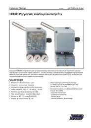
快 速 指 导 03.05 QG EVE0107 (en)<strong>SRI990</strong> 模 拟 阀 门 定 位 器此 说 明 书 是 用 于 使 定 位 器 快 速 启 动 的 指 导 。 如 果 需 要 更 多 具 体 的 信 息 , 请 参 见 标 准 文 件 “ 主 说 明 书 ” 和“ 产 品 规 格 单 ”。 这 些 文 件 可 以 在 我 公 司 的 网 站 www.foxboro-eckardt.com 找 到 。1. 安 装 到 执 行 机 构 上在 操 作 中 , 定 位 器 背 后 的 轴 9 的 平 面 必 须 总 是 面 向 箭 头 26。 围 绕 此 方 向 的 操 作 角 度 是 ±45º。$$''1.1 安 装 到 线 形 执 行 机 构 上NAMUR 标 准 安 装 直 接 安 装 NAMUR 标 准 安 装- 左 侧 - - 右 侧 -用 于 线 形 执 行 机 构 的 反 馈 杆 :承 载 螺 栓 B 在 反 馈 杆 A 的 长 孔 之 中 , 并 且 补 偿 弹 簧 要 接 触到 承 载 螺 栓 。承 载 螺 栓 B:1 螺 套2 柱 头 螺 栓3 接 合 件* .) ! $
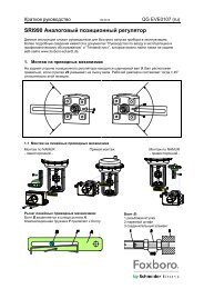
2 <strong>SRI990</strong> QG EVE0107 (en)1.2 安 装 到 角 行 程 执 行 机 构 上• 不 要 将 埋 头 螺 钉 4 与 轴 9 的 螺 纹 拧 紧 。• 当 在 使 用 中 , 轴 9 的 平 面 必 须 在 箭 头 26 的 前 面 移 动 ( 0 ↔ 100%)。• 当 产 品 的 温 度 上 升 时 , 传 动 轴 1 的 长 度 增 加 。 因 此 ,必 须 安 装 旋 转 适 配 器 3, 以 便 于 在 传 动 轴 1 和 旋 转 适 配器 3 之 间 留 有 大 约 1mm(0.04in.) 的 间 隙 。 在 安 装 旋 转 适配 器 之 前 , 通 过 在 反 馈 杆 9 上 加 上 适 当 数 量 的 垫 圈 5 来实 现 此 目 的 。2 个 垫 圈 可 形 成 1mm 的 间 隙 。执 行 机 构 , 向 左 旋 转执 行 机 构 , 向 右 旋 转''##"!"!2 气 动 连 接气 源 :1.4 to 6 bar( 但 不 能 大 于 执 行 机 构 的 最 大 压 力 ), 无 油 、 灰 尘 和 水 !OIIIO O O 单 作 用 , 直 接 安 装 单 作 用 双 作 用s 气 源 y1, y2 气 动 输 出 (--) 关 闭
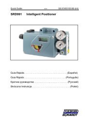
QG EVE0107 (en) <strong>SRI990</strong> 33. 电 动 连 接必 须 遵 守 文 件 EX EVE0001 的 安 全 要 求 和 SRD990 的 PSS EVE0107 文 件 和 MI EVE0107 文 件 中 的 要求 !3.3 限 位 开 关<strong>SRI990</strong>-xxxT or U遵 照 DIN 19234 或 NAMUR 标 准 的两 线 制 传 感 器供 给 电 压 DC 8 V带 有 本 安 控 制 电 路 的 开 关 放 大 器带 有 本 安 控 制 电 路 的 开 关 放 大 器<strong>SRI990</strong>-xxxV3.1 设 定 点 `3.2 位 置 反 馈 4-20 mA(<strong>SRI990</strong>-xxQ)警 告 : 对 于 连 接 微 动 开 关 , 请 参 见 主说 明 书 并 参 考 在 文 件 EX EVE0001中 所 描 述 的 安 全 要 求 。 `输 入 4 -20 mA模 拟 输 出 4-20 mA,两 线 制 ,供 给 电 压 DC 8 到 48 V*4 启 动 ( 通 过 现 场 开 关 和 电 位 计 的 方 式 来 设 置 )4.1 初 始 设 置在 定 位 器 安 装 到 执 行 机 构 、 气 源 以 及 电 输 入连 接 完 成 后 , 步 骤 如 下 :.首 先 , 所 有 开 关 必 须 在 位 置 I。 这 是 用 于 “4 to 20 mA”输 入 信 号 的 设 置 。 然 后 “ 左 侧 安 装 ”( 逆 时 针 旋 转 )* 对 于 本 安 电 路 , 请 参 照 认 证 / 最 大 操 作 电 压 的 数 据 标 签 等 等 。
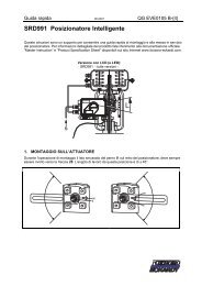
4 <strong>SRI990</strong> QG EVE0107 (en)4.2 配 置 反 馈 杆 的 旋 转 方 向从 定 位 器 的 前 面 看 , 来 定 义 反 馈 杆 从 起 点 运 动 到终 点 位 置 的 旋 转 方 向 。 如 有 需 要 , 转 换 1+2 到 “R”的 位 置 。R= 向 右 旋 转 ( 顺 时 针 ) L= 向 左 旋 转 ( 逆 时 针 )4.3 设 置 零 点 、 量 程 和 增 益a) 输 入 4 mA 电 信 号 。b) 旋 拧 电 位 计 P3 来 调 节 零 点 (ZERO), 直 到 执 行 机 构 从 它的 底 端 开 始 运 动 。向 右 旋 拧 P3: 零 点 增 大向 左 旋 拧 P3: 零 点 减 小c) 输 入 20 mA 电 信 号d) 旋 拧 电 位 计 P2 来 调 节 量 程 (S), 直 到 执 行 机 构 准 确 的 达 到它 的 底 端 。向 右 旋 拧 P2: 量 程 增 大向 左 旋 拧 P2: 量 程 减 小e) 定 位 器 的 循 环 放 大 功 能 通 过 电 位 计 P4 来 设 置 。 调 整 增 益以 避 免 在 连 续 给 出 输 入 值 的 时 候 , 执 行 机 构 震 颤 。f) 再 检 查 零 点 和 量 程 设 置 。.5 设 置 和 位 置 变 送 器 4-20mA 启 动必 须 保 证 位 置 变 送 器 的 电 气 连 接 。 然 后 两 个 LED’s 指 示 灯 点亮 。校 准 测 量 范 围 的 起 点 (4mA)a) 将 执 行 机 构 移 动 到 开 始 的 位 置 。b) 按 下 S1“ 配 置 4mA 输 出 ” 按 钮 , 时 长 大 于 2 秒 种 。 此时 ,LED1 点 亮 。2 秒 钟 后 , 两 个 LED’s 指 示 灯 再 次 点亮 ,4mA 的 值 被 存 储 下 来 。校 准 测 量 范 围 的 终 点 (20mA)a) 将 执 行 机 构 移 动 到 终 点 的 位 置 。b) 按 下 S2“ 配 置 20mA 输 出 ” 按 钮 , 时 长 大 于 2 秒 种 。 此 时 ,LED2 点 亮 。2 秒 钟 后 , 两 个 LED’s 指示 灯 再 次 点 亮 ,20mA 的 值 被 存 储 下 来 。福 克 斯 波 罗 - 埃 卡 特 股 份 有 限 公 司 – Pragstrasse 82 – D-70376 斯 图 加 特 – 德 国 – 电 话 : + 49 (0) 711 502 0埃 卡 特 S.A.S. – 20 rue de la Marne – F-68360 Soultz – 法 国 – 电 话 : +33 (0)3 89 62 15 30
Quick Guide 03.05 QG EVE0107 (en)<strong>SRI990</strong> Analog <strong>Positioner</strong>These instructions are to be used as a guide for quick start-up. For more detailed information pleaserefer to the standard documents “Master Instructions” and “Product Specification Sheet”. These canbe found on our Website www.foxboro-eckardt.com .1. Mounting to actuatorsDuring operation the flat side of the spindle 9 on the back of the positioner must always point towardsthe arrow 26. The working angle around this position is ± 45°$$''1.1 Mounting to linear actuatorsNAMUR mounting Direct mounting NAMUR mounting- left hand - - right hand -Feedback lever for linear actuators:The carrier bolt B is in the slot of the feedback lever Aand the compensating spring F touches the carrier bolt.* .)Carrier bolt B:1 threaded sleeve2 Stud3 coupling piece ! $
2 <strong>SRI990</strong> QG EVE0107 (en)1.2 Mounting to rotary actuators• Do not tighten grub screw 4 against the thread ofspindle 9 !• When in use the flat side of the spindle 9 must move( 0 ↔ 100%) in front of the arrow 26.• When the product temperature rises, the drive shaft1 increases in length. Therefore, the rotary adaptor 3must be mounted so that approx. 1 mm (0.04 in.) ofclearance results between the drive shaft 1 and therotary adaptor 3. This is achieved by placing anappropriate number of washers 5, on the feedbackspindle 9, before attaching the rotary adaptor. Twowashers should result in a clearance of 1 mmActuator, left turningActuator, right turning''##"!"!2 Pneumatic connectionsAir supply (s): 1,4 to 6 bar (but not more than the max. pressure of actuator), free of oil, dust and water !OIIIO O O Single acting, direct mounting Single acting Double actings air supply y1, y2 pneumatic outputs (--) closed
QG EVE0107 (en) <strong>SRI990</strong> 33. Electrical connectionsThe safety requirements of document EX EVE0001 as well as the requirements of PSS EVE0107 andMI EVE0107 for <strong>SRI990</strong> must be observed!3.3 Limit switch<strong>SRI990</strong>-xxxT or UTwo-wire proximity sensors,Acc. to DIN 19234 or NAMURSupply voltage DC 8 VSwitching amplifier withintrinsically safe control circuitSwitching amplifier withintrinsically safe control circuit<strong>SRI990</strong>-xxxV3.1 Setpoint ` `Input 4 to 20 mA3.2 Positionfeedback 4-20 mA(<strong>SRI990</strong>-xxQ)Analog output 4 to 20 mA,Two-wire system,Supply voltage DC 8 to 48 V*Warning: For connection of microswitches please refer to MI (MasterInstruction) and respect the safetyrequirements described in documentEX EVE0001.4 START UP (setting by means of local switches and potentiometers)4.1 Initial settingAfter mounting the positioner on theactuator, air and electrical input connected,proceed as follow.First all switches must be in position I. Thisis the setting for Input signal “4 to 20 mA”and “Left mounted” (counter clockwiserotation).* For intrinsically safe circuits please refer to certificate / data label for max. operating voltages etc.
4 <strong>SRI990</strong> QG EVE0107 (en)4.2 Configuration direction of rotation of feedback shaftDefined as direction of rotation of feedbackshaft from the start to the end position, lookingat the positioner from the front. Switch 1+2 to“R” if necessary.R= right turn (clockwise) L= left turn (counter cw)4.3 Setting of zero, span and gaina) Apply 4 mA to Input.b) Turn potentiometer P3 for zero point (ZERO) untilactuator just begins to move from its end position.Rotation P3 to the right: zero point is increasedRotation P3 to the left: zero point is reducedc) Apply 20 mA to Inputd) Turn potentiometer P2 for span (S) until actuatorexactly reaches its end position.Rotation P2 to the right: span is increasedRotation P2 to the left: span is reducede) The loop amplification of the positioner is set viapotentiometer P4. Trim the gain so that the actuatorwill not swing at constant given input value.f) Re-check zero and span settings.5 Setting and Start Up of position transmitter 4-20mAThe electronic connection of the position transmitter must beassured. Both LED’s are then light up.Adjusting the start of the measuring range (4mA)a) Move the actuator to the starting position.b) Press push button S1 „Config Output 4mA“ longer than2 seconds. During this time LED 1 lights up. After 2seconds both LED’s are light up again, the value for 4mAis stored.Adjusting the end of the measuring range (20mA)a) Move the actuator to the end position.b) Press push button S2 „Config Output 20mA“ longer than 2 seconds. During this time LED 2 lightsup. After 2 seconds both LED’s are light up again, the value for 20mA is stored.Foxboro Eckardt GmbH – Pragstrasse 82 – D-70376 Stuttgart – Germany – Tel. + 49 (0) 711 502 0Eckardt S.A.S. – 20 rue de la Marne – F-68360 Soultz – France – Tel. +33 (0)3 89 62 15 30
快 速 指 导QG EVE0107 (int)
<strong>SRI990</strong>QG EVE0107 (int)此 产 品 的 附 加 文 件 :定 位 器 附 件 的 技 术 信 息TI EVE0011 A 所 有 定 位 器 附 件 安 装 在 不 同 制 造 商 的 执 行 机 构 / 阀 门 的 综 述快 速 指 导QG EVE0107 A主 说 明 书 :MI EVE010/ A用 于 其 他 产 品 的 附 加 文 件 :产 品 说 明 书PSS EVE0109 A-(en)PSS EVE0105 A-(en)PSS EVE0106 A-(en)PSS EVE0107 A-(en)PSS EVE0103 A-(en)PSS EVE0102 A-(en)PSS EVE0101 A-(en)主 说 明 书 的 摘 录 , 使 用 简 单 , 容 易 理 解 且 可 快 速 开 始 使 用 产 品 。 此 文 件 突 出 了说 明 书 中 最 重 要 的 内 容 。<strong>SRI990</strong> 模 拟 阀 门 定 位 器SRD960 通 用 阀 门 定 位 器SRD991 智 能 阀 门 定 位 器SRD992 数 字 式 阀 门 定 位 器<strong>SRI990</strong> 模 拟 阀 门 定 位 器SRI983 电 气 阀 门 定 位 器 - 防 爆 或 EEx d 型SRI986 电 气 阀 门 定 位 器SRP981 气 动 阀 门 定 位 器备 件 :可 在 此 网 址 浏 览 : http://service.foxboro-eckardt.com/cgi-bin/ersatzteile.pl?0+en禁 止 翻 版 、 复 制 和 翻 译 等 行 为 。 此 处 正 常 引 用 的 产 品 和 出 版 物 与 现 有 的 的 专 利 权 、 已 注 册 的 实 用 新 型 或商 标 无 关 。 缺 少 任 何 此 类 相 关 权 利 并 不 证 明 一 个 产 品 或 符 号 不 受 保 护 。福 克 斯 波 罗 — 埃 卡 特 股 份 有 限 公 司埃 卡 特 S.A.S.Pragstrasse 8220 rue de la MarneD-70376 斯 图 加 特 F-68360 Soultz德 国法 国电 话 :+ 49(0)711 502-0 电 话 :+ 33 (0)3 89 62 15 30传 真 :+ 49(0)711 502-597 传 真 :+ 33 (0)3 89 62 14 85http://www.foxboro-eckardt.com 文 件 536 022 134 http://www.eckardt.frhttp://www.foxboro-eckardt.de