Automatismo para puerta corredera LineaMatic - Hörmann
Automatismo para puerta corredera LineaMatic - Hörmann
Automatismo para puerta corredera LineaMatic - Hörmann

Create successful ePaper yourself
Turn your PDF publications into a flip-book with our unique Google optimized e-Paper software.
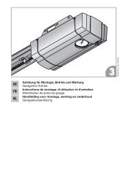
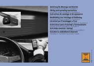
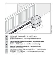
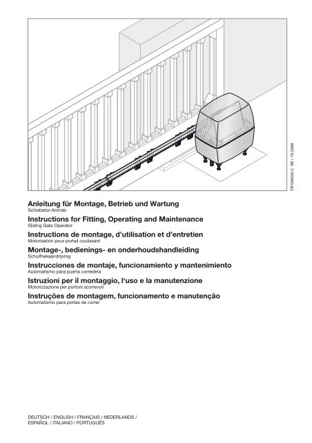
TR10A059-C RE / 10.2008Anleitung für Montage, Betrieb und WartungSchiebetor-AntriebInstructions for Fitting, Operating and MaintenanceSliding Gate OperatorInstructions de montage, d’utilisation et d’entretienMotorisation pour portail coulissantMontage-, bedienings- en onderhoudshandleidingSchuifhekaandrijvingInstrucciones de montaje, funcionamiento y mantenimiento<strong>Automatismo</strong> <strong>para</strong> <strong>puerta</strong> <strong>corredera</strong>Istruzioni per il montaggio, l‘uso e la manutenzioneMotorizzazione per portoni scorrevoliInstruções de montagem, funcionamento e manutenção<strong>Automatismo</strong> <strong>para</strong> portas de correrDeutsch / English / Français / Nederlands /Español / Italiano / Português
DEUTSCH ........................ 5ENGLISH ........................ 20FRANÇAIS ....................... 35NEDERLANDS. ................... 51ESPAÑOL. ....................... 67ITALIANO. ....................... 83PORTUGUÊS. .................... 99..................... 1152 TR10A059-C RE / 10.2008
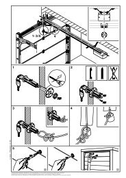
AB17 mm23 mmØ 5,5 mmØ 12 mmTR10A059-C RE / 10.2008 3
C 16 x 6 x438 634C 2438 6322/2.2a401020286.517.5C 3438 63128366.517.5 7.5C 4438 759 2/2.2bC438 76558.29828.58 10.53725307.52401001002409202/2.2a240920100 10024010206 8.7521004450 4504 TR10A059-C RE / 10.2008
DEUTSCHKraft-LernfahrtBei dieser Lernfahrt werden die Kräfte eingelernt, die für dasVerfahren des Tores notwendig sind.NormalfahrtVerfahren des Tores mit den eingelernten Strecken undKräften.ReferenzfahrtTorfahrt in Richtung Endlage Tor-Zu, um die Grundstellungfestzulegen.ReversierfahrtVerfahren des Tores in Gegenrichtung beim Ansprechen derSicherheitseinrichtungen.ReversiergrenzeDie Reversiergrenze trennt den Bereich zwischenReversierfahrt und Stoppen des Tores bei Kraftabschaltung inEndlage Tor-Zu.SchleichfahrtDer Bereich in dem das Tor sehr langsam verfährt, um sanftgegen die Endlage zu fahren.TeilöffnungDer Verfahrweg, der für den Personendurchgang geöffnetwird.Totmann-FahrtTorfahrt, die nur so lange durchgeführt wird, wie dieentsprechenden Taster betätigt werden.VollöffnungDer Verfahrweg, wenn das Tor vollständig geöffnet wird.VorwarnzeitDie Zeit zwischen dem Fahrbefehl (Impuls) und dem Beginnder Torfahrt.WerksresetZurücksetzen der eingelernten Werte in denAuslieferungszustand / die Werkseinstellung.Farbcode für Leitungen, Einzeladern und BauteileDie Abkürzungen der Farben für Leitung- undAderkennzeichnung sowie Bauteilen folgen deminternationalen Farbcode nach IEC 757:BK Schwarz PK RosaBN Braun RD RotBU Blau SR SilberGD Gold TQ TürkisGN Grün VT ViolettGN/YE Grün/Gelb WH WeißGY Grau YE GelbOGOrange44.1MontageVorbereitung der MontageWARNUNGVerletzungsgefahr durch beschädigte BauteileDie Toranlage darf nicht benutzt werden, wenn Re<strong>para</strong>turoderEinstellarbeiten durchgeführt werden müssen. EinFehler in der Toranlage oder ein falsch ausgerichtetes Torkann zu schweren Verletzungen führen.ff Kontrollieren Sie die gesamte Toranlage (Gelenke,Lager des Tores und Befestigungsteile) auf Verschleißund eventuelle Beschädigungen. Prüfen Sie, ob Rost,Korrosion oder Risse vorhanden sind.ff Betreiben Sie den Schiebetor-Antrieb nur, wenn Sieden Bewegungsbereich des Tores einsehen können.ff Vergewissern Sie sich vor der Ein- bzw. Ausfahrt, obdas Tor auch ganz geöffnet wurde. Toranlagen dürfenerst durchfahren bzw. durchgangen werden, wenn dasTor zum Stillstand gekommen ist.Bevor Sie den Antrieb installieren, lassen Sie zu Ihrer eigenenSicherheit eventuell erforderliche Wartungs- undRe<strong>para</strong>turarbeiten an der Toranlage durch einenSachkundigen ausführen.Nur die korrekte Montage und Wartung durch einenkompetenten/sachkundigen Betrieb oder eine kompetente/sachkundige Person in Übereinstimmung mit den Anleitungenkann die sichere und vorgesehene Funktionsweise einerMontage sicherstellen.Der Sachkundige muss darauf achten, dass bei derDurchführung der Montagearbeiten die geltenden Vorschriftenzur Arbeitssicherheit sowie die Vorschriften für den Betriebvon elektrischen Geräten befolgt werden. Hierbei müssenauch die nationalen Richtlinien beachtet werden. MöglicheGefährdungen werden durch die Konstruktion und Montagenach unseren Vorgaben vermieden.ff Alle Sicherheits- und Schutzfunktionen müssenmonatlich geprüft werden. Falls erforderlich, müssen dieFehler bzw. Mängel sofort behoben werden.Vor der Montage und Bedienung der Toranlage:WARNUNGQuetsch- und Schergefahr an den SchließkantenBei der Torfahrt können Finger oder Gliedmaßen zwischenTor und Schließkante eingequetscht oder abgetrenntwerden.ff Berühren Sie während einer Torfahrt nicht die HauptundNebenschließkanten.ff Weisen Sie alle Personen, welche die Toranlagebenutzen, in die ordnungsgemäße und sichere Bedienungein.ff Demonstrieren und testen Sie die mechanischeEntriegelung sowie den Sicherheitsrücklauf. Halten Siedazu das Tor während des Torlaufes mit beiden Händenan. Die Toranlage muss den Sicherheitsrücklauf einleiten.8 TR10A059-C RE / 10.2008
DEUTSCHImpulssteuerung:ffErster Kontakt an Klemme 21ffZweiter Kontakt an Klemme 20Teilöffnung:ffErster Kontakt an Klemme 23ffZweiter Kontakt an Klemme 20Hinweis:Wird für einen externen Taster eine Hilfsspannung benötigt, sosteht dafür an der Klemme 5 eine Spannung von +24 V DC(gegen die Klemme 20 = 0 V) bereit.4.10.3 Anschluss eines Ausschalters zum Anhaltendes Antriebes (Halt- bzw. Not-Aus-Kreis)Ein Ausschalter mit Öffnerkontakten (nach 0 V schaltend oderpotentialfrei) wird wie folgt angeschlossen (siehe Bild 4.3):1. Die werkseitig eingesetzte Drahtbrücke zwischenKlemme 12 und Klemme 13 entfernen.–– Klemme 12: Halt- bzw. Not-Aus-Eingang–– Klemme 13: 0 V, ermöglicht eine normale Funktiondes Antriebes2. Schaltausgang oder ersten Kontakt an Klemme 12 (Haltbzw.Not-Aus-Eingang) anschließen.3. 0 V (Masse) oder zweiten Kontakt an Klemme 13 (0 V)anschließen.Hinweis:Durch das Öffnen des Kontaktes werden eventuelle Torfahrtensofort angehalten und dauerhaft unterbunden.4.10.4 Anschluss einer Warnleuchte*ffSiehe Bild 4.4(*Zubehör, ist nicht in der Standard-Ausstattung enthalten!)An den potentialfreien Kontakten am Stecker Option kanneine Warnleuchte oder die Endlagenmeldung Tor-Zuangeschlossen werden.Für den Betrieb (z.B. Warnmeldungen vor und während derTorfahrt) mit einer 24 V Lampe (max. 7 W) kann die Spannungam Stecker 24 V = herangezogen werden.Hinweis:Eine 230 V-Warnleuchte (siehe Endlagenerfassung Tor-Zudurch Endschalter, Seite 12) muss direkt versorgt werden.4.10.5 Anschluss von Sicherheits-/SchutzeinrichtungenffSiehe Bild 4.5-4.7Es können Sicherheitseinrichtungen wie Lichtschranken/Schließkantensicherungen (SKS) oder8k2-Widerstandskontaktleisten angeschlossen werden:SE1SE2SE3in Richtung Öffnen, Sicherheitseinrichtung getestetoder Widerstandskontaktleiste 8k2.in Richtung Schließen, Sicherheitseinrichtunggetestet oder Widerstandskontaktleiste 8k2.in Richtung Schließen, Lichtschranke ohneTestung oder dynamische 2-Draht-Lichtschranke,z.B. als Durchfahrtslichtschranke.Die Auswahl für die 3 Sicherheitskreise kann über DIL-Schalter eingestellt werden (siehe Übersicht und Einstellungender DIL‐Schalter, Seite 13).Klemme 20Klemme 18Klemmen 71/72/73Klemme 50 V (Spannungsversorgung)TestsignalSignal der Sicherheitseinrichtung+24 V (Spannungsversorgung)Hinweis:Sicherheitseinrichtungen ohne Testung (z.B. statischeLichtschranken) müssen halbjährlich geprüft werden. Sie sindnur für den Sachschutz zulässig!4.10.6 Anschluss BUSffSiehe Bild 4.85 Inbetriebnahmeff Vor der Erstinbetriebnahme alle Anschlussleitungen aufdie korrekte Installation an allen Anschlussklemmenüberprüfen.ff Das Tor halb öffnen.ff Den Antrieb einkuppeln.5.1 AllgemeinesDie Steuerung wird mittels DIL-Schalter programmiert.Änderungen der DIL-Schaltereinstellungen sind nur unterfolgenden Voraussetzungen zulässig:• Der Antrieb steht.• Es ist keine Vorwarn- oder Aufhaltezeit aktiv.5.2 Übersicht EinrichtbetriebIn folgenden Kapiteln wird der Einrichtbetrieb beschrieben:• Vorbereitung, Seite 11• Einlernen der Torendlagen, Seite 11––Endlagenerfassung Tor-Zu durch Endschalter,Seite 12––Endlagenerfassung Tor-Auf, Seite 12––Endlagenerfassung Teilöffnung, Seite 12• Kräfte lernen, Seite 12• Startpunkte für Schleichfahrt beim Öffnen und Schließenändern, Seite 13• Reversiergrenze, Seite 135.3 Vorbereitungff Alle DIL-Schalter müssen sich in der Werkseinstellungbefinden, d.h. alle Schalter stehen auf OFF (siehe Bild 5).Folgende DIL-Schalter umstellen:f f DIL-Schalter 1: Einbaurichtung (siehe Bild 5.1)ON Tor schließt nach rechts(vom Antrieb aus gesehen)Tor schließt nach linksOFF (vom Antrieb aus gesehen)f f DIL-Schalter 3-7: Sicherheitseinrichtungenentsprechend einstellen (siehe Kapitel DIL-Schalter 3 /DIL-Schalter 4 bis DIL-Schalter 7 ab Seite 13).5.4 Einlernen der Torendlagenf f DIL-Schalter 2: Einrichtbetrieb (siehe Bild 6.1)ON Einlernen des VerfahrwegesOFFTR10A059-C RE / 10.2008 11
DEUTSCHHinweis:Im Einrichtbetrieb sind die Sicherheitseinrichtungen nichtaktiv.5.4.1 Endlagenerfassung Tor-Zu durch EndschalterVor dem Einlernen der Endlagen muss der Endschalter (Reed-Kontakt) angeschlossen sein. Die Adern des Endschaltersmüssen an der Klemme REED angeklemmt sein (sieheBild 6.1a). Das Optionsrelais hat beim Einrichten die gleicheFunktion wie die rote LED. Mit einer hier angeschlossenenLampe lässt sich die Endschalterstellung aus der Fernebeobachten (siehe Bild 4.4).Einlernen der Endlage Tor-Zu:1. Das Tor etwas öffnen.2. Den Platinentaster T drücken und gedrückt halten.Das Tor fährt nun in Schleichfahrt in Richtung Tor-Zu. BeiErreichen des Endschalters erlischt die rote LED.3. Den Platinentaster T unverzüglich loslassen.Das Tor befindet sich nun in der Endlage Tor-Zu.Hinweis:Fährt das Tor in Richtung Auf, befindet sich derDIL‐Schalter 1 in der falschen Position und muss umgestelltwerden. Anschließend die Schritte 1 bis 3 wiederholen.Falls diese Position des geschlossenen Tores nicht dergewünschten Endlage Tor-Zu entspricht, muss nachjustiertwerden.Endlage Tor-Zu nachjustieren:1. Die Position des Magneten durch Verschieben desMagnetschlittens verändern.2. Platinentaster T drücken, um der so verstellten Endlagezu folgen, bis die rote LED wieder erlischt.3. Diesen Vorgang so lange wiederholen, bis diegewünschte Endlage erreicht ist.5.4.2 Endlagenerfassung Tor-AufffSiehe Bild 6.1bEinlernen der Endlage Tor-Auf:1. Den Platinentaster T drücken und gedrückt halten.Das Tor fährt in Schleichfahrt auf.2. Ist die gewünschte Endlage Tor-Auf erreicht, denPlatinentaster T loslassen.3. Platinentaster P drücken, um diese Position zubestätigen.Die grüne LED signalisiert durch ein 2 Sekunden langes,sehr schnelles Blinken das Erfassen der Endlage Tor-Auf.5.4.3 Endlagenerfassung TeilöffnungEinlernen der Endlage Teilöffnung:1. Den Platinentaster T drücken und gedrückt halten, umdas Tor in Richtung Tor-Zu zu fahren.2. Ist die gewünschte Endlage Teilöffnung erreicht, denPlatinentaster T loslassen.3. Platinentaster P drücken um diese Position zubestätigen.Die grüne LED signalisiert durch langsames Blinken dasErfassen der Endlage Teilöffnung.5.4.4 Abschluss des EinrichtbetriebesffNach Abschluss des Einlernvorgangs DIL‐Schalter 2(Funktion: Einlernen des Verfahrweges) auf OFF stellen.Die grüne LED signalisiert durch schnelles Blinken, dassKraftlernfahrten durchgeführt werden müssen (sieheBild 6.1c).Hinweis:Die Sicherheitseinrichtungen werden aktiv geschaltet.5.4.5 ReferenzfahrtffSiehe Bild 6.2Nach dem Einlernen der Endlagen ist die erste Fahrt immereine Referenzfahrt. Während der Referenzfahrt wird dasOptionsrelais getaktet und eine angeschlossene Warnleuchteblinkt.Referenzfahrt bis Endlage Tor-Zu:ffDen Platinentaster T einmal drücken.Der Antrieb fährt selbständig bis in die Endlage Tor-Zu.5.5 Kräfte lernenNach dem Einlernen der Endlagen und der Referenzfahrtmüssen die Kräfte in Kraftlernfahrten eingelernt werden.Hierfür sind drei ununterbrochene Tor-Zyklen erforderlich, beidenen keine Sicherheitseinrichtung ansprechen darf. DieErfassung der Kräfte erfolgt in beide Richtungen automatischim Selbsthaltebetrieb, d.h. der Antrieb verfährt nach einemImpuls selbständig bis in die Endlage. Während des gesamtenLernvorgangs blinkt die grüne LED. Nach Abschluss derKraftlernfahrten leuchtet diese dann kontinuierlich.ff Die beiden folgenden Vorgänge müssen dreimaldurchgeführt werden.Kraftlernfahrt bis Endlage Tor-Auf:ffDen Platinentaster T einmal drücken.Der Antrieb fährt selbständig bis in die Endlage Tor-Auf.Kraftlernfahrt bis Endlage Tor-Zu:ffDen Platinentaster T einmal drücken.Der Antrieb fährt selbständig bis in die Endlage Tor-Zu.Kraftbegrenzung einstellen:WARNUNGVerletzungsgefahr bei zu hoher KraftbegrenzungBei einer zu hoch eingestellten Kraftbegrenzung stoppt dasTor beim Schließen nicht rechtzeitig und kann dabeiPersonen oder Gegenstände einklemmen.ff Stellen Sie keine zu hohe Kraftbegrenzung ein.Hinweis:Aufgrund besonderer Einbausituationen kann es vorkommen,dass die zuvor gelernten Kräfte nicht ausreichen, was zuungewollten Reversiervorgängen führen kann. In solchenFällen kann die Kraftbegrenzung nachgestellt werden.1. Zum Einstellen der Kraftbegrenzung der Toranlage für dieAuf- und Zufahrt steht ein Potentiometer zur Verfügung,welches auf der Steuerungsplatine im Antrieb mit Kraft Fbeschriftet ist.Die Erhöhung der Kraftbegrenzung erfolgt prozentual zuden gelernten Werten; dabei bedeutet die Stellung desPotentiometers die folgende Kraft-Zunahme (sieheBild 7.1):12 TR10A059-C RE / 10.2008
DEUTSCHLinksanschlagMittelstellungRechtsanschlag+ 0 % Kraft+15 % Kraft+75 % Kraft2. Die eingelernte Kraft mittels einer geeignetenKraftmesseinrichtung auf zulässige Werte imGeltungsbereich der EN 12453 und EN 12445 oder denentsprechenden nationalen Vorschriften prüfen.5.6 Startpunkte für Schleichfahrt beim Öffnen undSchließen ändernDie Länge der Schleichfahrt wird nach dem Einlernen derEndlagen automatisch auf einen Grundwert von ca. 500 mmvor den Endlagen gesetzt. Die Startpunkte können auf eineLänge von minimal ca. 300 mm bis zur gesamten Torlängeumprogrammiert werden (siehe Bild 7.2).Einrichten der Positionen – Schleichfahrt:1. Die Endlagen müssen eingerichtet sein und das Tor musssich in Endlage Tor-Zu befinden.2. Der DIL-Schalter 2 muss auf OFF stehen.3. Zum Einrichten der Startpunkte für Schleichfahrt denDIL-Schalter 12 auf ON stellen.4. Platinentaster T drücken.Das Tor fährt in Normalfahrt mit Selbsthaltung in RichtungTor-Auf.5. Passiert das Tor die gewünschte Position für den Beginnder Schleichfahrt, den Platinentaster P kurz drücken.Das Tor fährt die restliche Strecke zur Endlage Tor-Auf inSchleichfahrt.6. Platinentaster T nochmals drücken.Das Tor fährt wieder in Normalfahrt mit Selbsthaltung inRichtung Tor-Zu.7. Passiert das Tor die gewünschte Position für den Beginnder Schleichfahrt, den Platinentaster P kurz drücken.Das Tor fährt die restliche Strecke zur Endlage Tor-Zu inSchleichfahrt.8. Den DIL-Schalter 12 auf OFF stellen.Das Einstellen der Startpunkte für Schleichfahrt istabgeschlossen.Hinweis:Die Startpunkte der Schleichfahrt können auch überlappendeingestellt werden; in diesem Fall wird die ganzeFlügelbewegung in Schleichfahrt durchgeführt.Das Ändern der Startpunkte für Schleichfahrt hat zur Folge,dass die bereits eingelernten Kräfte gelöscht werden. NachAbschluss der Änderung signalisiert das Blinken der grünenLED, dass erneut Kraftlernfahrten durchgeführt werdenmüssen.ff Die beiden folgenden Vorgänge müssen dreimaldurchgeführt werden.Kraft-Lernfahrt bis Endlage Tor-Auf:ffDen Platinentaster T einmal drücken.Der Antrieb fährt selbständig bis in die Endlage Tor-Auf.Kraft-Lernfahrt bis Endlage Tor-Zu:ffDen Platinentaster T einmal drücken.Der Antrieb fährt selbständig bis in die Endlage Tor-Zu.verfährt in Gegenrichtung) läuft. Der Grenzbereich lässt sichwie folgt verändern (siehe Bild 7.3).Reversiergrenze einstellen:1. DIL-Schalter 11 auf ON stellen.Die Reversiergrenze kann nun stufig eingestellt werden.2. Platinentaster P kurz drücken, um die Reversiergrenze zuverringern.oderPlatinentaster T kurz drücken, um die Reversiergrenze zuvergrößern.Beim Einstellen der Reversiergrenzen zeigt die grüne LEDdie folgenden Einstellungen an:1x blinkenbis10x blinkenminimale Reversiergrenze, die grüneLED blinkt einmalmaximale Reversiergrenze, die grüneLED blinkt max. 10 mal3. DIL-Schalter 11 wieder auf OFF stellen, um dieeingestellte Reversiergrenze zu speichern.5.8 Übersicht und Einstellungen der DIL‐SchalterÄnderungen der DIL-Schalter-Einstellungen sind nur unterfolgenden Voraussetzungen zulässig:• Der Antrieb steht.• Es ist keine Vorwarn- oder Aufhaltezeit aktiv.Entsprechend der nationalen Vorschriften, den gewünschtenSicherheitseinrichtungen und den örtlichen Gegebenheitenmüssen die DIL-Schalter wie in den folgenden Abschnittenbeschrieben eingestellt werden.5.8.1DIL-Schalter 1Einbaurichtung:ffSiehe Kapitel Vorbereitung, Seite 115.8.2DIL-Schalter 2Einrichtbetrieb:ffSiehe Kapitel Einlernen der Torendlagen, Seite 115.8.3 DIL-Schalter 3 / DIL-Schalter 4Sicherheitseinrichtung SE 1 (Öffnen):ffSiehe Bild 7.4Mit DIL-Schalter 3 in Kombination mit DIL-Schalter 4werden Art und Wirkung der Sicherheitseinrichtungeingestellt.3 ON Anschlusseinheit Schließkantensicherung oderLichtschranke mit Testung3 OFF • Widerstandskontaktleiste 8k2• keine Sicherheitseinrichtung (Widerstand 8k2zwischen Klemme 20/72,Auslieferungszustand)4 ON verzögertes kurzes Reversieren in Richtung Tor-Zu(für Lichtschranke)4 OFF sofortiges kurzes Reversieren in Richtung Tor-Zu(für SKS)5.7 ReversiergrenzeBeim Betrieb der Toranlage muss bei der Fahrt in RichtungTor-Zu unterschieden werden, ob das Tor gegen denEndanschlag (Toranlage stoppt) oder gegen ein Hindernis (TorTR10A059-C RE / 10.2008 13
DEUTSCH5.8.4DIL-Schalter 5 / DIL-Schalter 6ffSiehe Bild 7.7dSicherheitseinrichtung SE 2 (Schließen):ffSiehe Bild 7.5Mit DIL-Schalter 5 in Kombination mit DIL-Schalter 6werden Art und Wirkung der Sicherheitseinrichtungeingestellt.5 ON Anschlusseinheit Schließkantensicherung oderLichtschranke mit Testung5 OFF • Widerstandskontaktleiste 8k2• keine Sicherheitseinrichtung (Widerstand 8k2zwischen Klemme 20/73,Auslieferungszustand)6 ON verzögertes kurzes Reversieren in RichtungTor-Auf (für Lichtschranke)6 OFF sofortiges kurzes Reversieren in Richtung Tor-Auf(für SKS)5.8.5 DIL-Schalter 7Schutzeinrichtung SE 3 (Schließen):ffSiehe Bild 7.6Verzögertes Reversieren bis in Endlage Tor-Auf.7 ON Dynamische 2-Draht-Lichtschranke7 OFF • ungetestete statische Lichtschranke• keine Sicherheitseinrichtung (Drahtbrückezwischen Klemme 20/71,Auslieferungszustand)5.8.6 DIL-Schalter 8 / DIL-Schalter 9Mit DIL-Schalter 8 in Kombination mit DIL-Schalter 9werden die Funktionen des Antriebes (automatischer Zulauf /Vorwarnzeit) und die Funktion des Optionsrelais eingestellt.ffSiehe Bild 7.7a8 ON 9 ON Antriebautomatischer Zulauf, Vorwarnzeit beijeder TorfahrtOptionsrelaisDas Relais taktet bei der Vorwarnzeitschnell, während der Torfahrt normal undbei der Aufhaltezeit ist es aus.ffSiehe Bild 7.7b8 OFF 9 ON Antriebautomatischer Zulauf, Vorwarnzeit nurbei automatischem ZulaufOptionsrelaisDas Relais taktet bei der Vorwarnzeitschnell, während der Torfahrt normalund bei der Aufhaltezeit ist es aus.ffSiehe Bild 7.7c8 ON 9 OFF AntriebVorwarnzeit bei jeder Torfahrt ohneautomatischen ZulaufOptionsrelaisDas Relais taktet bei der Vorwarnzeitschnell, während der Torfahrt normal.8 OFF 9 OFF AntriebOhne besondere FunktionOptionsrelaisDas Relais zieht in der Endlage Tor-Zuan.Hinweis:Ein automatischer Zulauf ist immer nur aus den festgelegtenEndlagen (Voll- oder Teilöffnung) möglich. Ist einautomatischer Zulauf dreimal fehlgeschlagen, wird erdeaktiviert. Der Antrieb muss mit einem Impuls neu gestartetwerden.5.8.7DIL-Schalter 10Wirkung der Schutzeinrichtung SE3 alsDurchfahrtslichtschranke bei automatischem ZulaufffSiehe Bild 7.8Mit diesem Schalter wird die Schutzeinrichtung SE3 alsDurchfahrtslichtschranke bei automatischem Zulaufeingestellt.7 ON Die Lichtschranke ist alsDurchfahrtslichtschranke aktiviert, nachDurchfahrt oder Durchgang der Lichtschrankewird die Aufhaltezeit verkürzt.7 OFF Die Lichtschranke ist nicht alsDurchfahrtslichtschranke aktiviert. Ist aberautomatischer Zulauf aktiviert und ist nachAblauf der Aufhaltezeit die Lichtschrankeunterbrochen, wird die Aufhaltezeit wieder aufdie voreingestellte Zeit gesetzt.5.8.8DIL-Schalter 11Einrichten der Reversiergrenzen:ffSiehe Kapitel Reversiergrenze, Seite 135.8.9DIL-Schalter 12Startpunkt der Schleichfahrt beim Öffnen und Schließen:ffSiehe Kapitel Startpunkte für Schleichfahrt beim Öffnenund Schließen ändern, Seite 136Handsender6.1 BedienelementeffSiehe Bild 81 LED2 Bedientasten3 Batteriefachdeckel4 Batterie5 Reset-Taster6 Handsenderhalterung6.2 Wichtige Hinweise zum Gebrauch desHandsenders• Verwenden Sie für die Inbetriebnahme der Fernsteuerungausschließlich Originalteile.• Ist kein se<strong>para</strong>ter Zugang zur Garage vorhanden, soführen Sie jede Änderung oder Erweiterung vonProgrammierungen innerhalb der Garage durch.14 TR10A059-C RE / 10.2008
DEUTSCH• Führen Sie nach dem Programmieren oder Erweitern derFernsteuerung eine Funktionsprüfung durch.• Handsender gehören nicht in Kinderhände und dürfen nurvon Personen benutzt werden, die in die Funktionsweiseder ferngesteuerten Toranlage eingewiesen sind.• Die Bedienung des Handsenders muss generell mitSichtkontakt zum Tor erfolgen.• Toröffnungen von ferngesteuerten Toranlagen dürfen erstdurchfahren bzw. durchgangen werden, wenn dasGaragentor in der Endlage Tor-Auf steht.• Schützen Sie den Handsender vor folgendenUmwelteinflüssen:–– direkter Sonneneinstrahlung (zul.Umgebungstemperatur: –20 °C bis +60 °C)–– Feuchtigkeit–– StaubbelastungBei Nichtbeachtung kann die Funktion beeinträchtigtwerden!VorsichtUnbeabsichtigte TorfahrtWährend der Programmierung des Handsender kann es zuungewollten Torfahrten kommen.ff Achten Sie darauf, dass sich bei der Programmierungund Erweiterung der Fernsteuerung keine Personenoder Gegenstände im Bewegungsbereich des Toresbefinden.Hinweis:Die örtlichen Gegebenheiten können Einfluss auf dieReichweite der Fernsteuerung haben.6.3 Wiederherstellen des WerkscodesffSiehe Bild 8Hinweis:Nachfolgende Bedienschritte sind nur bei versehentlichenErweiterungs- oder Lernvorgängen erforderlich.Der Code-Platz jeder Taste des Handsenders kann wieder mitdem ursprünglichen Werkscode oder auch mit einem anderenCode belegt werden.1. Öffnen Sie den Batteriefachdeckel.Ein kleiner Taster ist auf der Platine zugänglich.AchtungZerstörung des Tastersff Verwenden Sie keine spitzen Gegenstände und drückenSie nicht zu stark auf den Taster.2. Drücken Sie den Taster 5 mit einem stumpfenGegenstand vorsichtig und halten Sie ihn gedrückt.3. Drücken Sie die Bedientaste, die codiert werden soll, undhalten Sie diese gedrückt.Die LED des Senders blinkt langsam.4. Wenn Sie den kleinen Taster bis zum Ende deslangsamen Blinkens gedrückt halten, wird dieBedientaste wieder mit dem ursprünglichen Werkscodebelegt und die LED beginnt schneller zu blinken.5. Schließen Sie den Batteriefachdeckel.6. Führen Sie eine neue Programmierung des Empfängersdurch.7 Funk-Fernsteuerung7.1 Integrierter FunkempfängerDer Schiebetor-Antrieb ist mit einem integriertenFunkempfänger ausgestattet. Bei dem integriertenFunkemfänger können die Funktionen Impuls (Auf-Stop-Zu-Stop) und Teilöffnung von je max. 12 verschiedenenHandsendertasten einprogrammiert werden. Werden mehr alsje 12 Handsendertasten programmiert, wird die als Erstesprogrammierte ohne Vorwarnung gelöscht. ImAuslieferungszustand sind alle Speicherplätze leer.Funk programmieren / Daten löschen ist nur möglich, wennfolgendes gilt:• Es ist kein Einrichtbetrieb aktiviert ( DIL-Schalter 2 aufOFF).• Die Flügel werden nicht verfahren.• Zur Zeit ist keine Vorwarn- oder Aufhaltezeit aktiv.Hinweis:Zum Betrieb des Antriebes mit Funk muss eineHandsendertaste an einem integrierten Funkempfängereinprogrammiert sein. Der Abstand zwischen Handsender undAntrieb sollte mindestens 1 m betragen. GSM-900-Handyskönnen bei gleichzeitiger Benutzung die Reichweite derFunkfernsteuerung beeinflussen.7.2 Einprogrammieren der Handsendertasten aneinem integrierten Funkempfänger1. Den Platinentaster P einmal (für Kanal 1 = Impuls-Befehl)oder zweimal (für Kanal 2 = Teilöffnung-Befehl) kurzdrücken.Ein weiteres Drücken des Platinentasters P beendet dieFunk-Programmierbereitschaft sofort.Je nachdem welcher Kanal einprogrammiert werden soll,blinkt die rote LED nun 1x (für Kanal 1) oder 2x (fürKanal 2). In dieser Zeit kann eine Handsendertaste für diegewünschte Funktion einprogrammiert werden.2. Die Handsendertaste, die einprogrammiert werden soll,so lange drücken, bis die rote LED auf der Platine schnellblinkt.Der Funk-Code dieser Handsendertaste ist nun imintegrierten Funkempfänger gespeichert (siehe Bild 9).7.3 Löschen aller Daten eines integriertenFunkempfängersffDen Platinentaster P drücken und gedrückt halten.Die rote LED blinkt langsam und signalisiert dieLöschbereitschaft. Das Blinken wechselt in einenschnelleren Rhythmus. Anschließend sind dieeinprogrammierten Funk-Codes aller Handsendertastengelöscht.7.3.1 Anschluss eines externen Funk-Empfängers*(*Zubehör, ist nicht in der Standard-Ausstattung enthalten!)Anstatt des integrierten Funkempfängers kann zum Ansteuerndes Schiebetor-Antriebes ein externer Funk-Empfänger für dieFunktionen Impuls bzw. Teilöffnung verwendet werden. DerStecker dieses Empfängers wird auf den entsprechendenSteckplatz gesteckt (siehe Bild 4.1). Um Doppelbelegungenzu vermeiden, sollte für den Betrieb mit einem externen Funk-Empfänger die Daten des integrierten Funkempfängersgelöscht werden (siehe Löschen aller Daten eines integriertenFunkempfängers, Seite 15).TR10A059-C RE / 10.2008 15
DEUTSCH8Den Schiebetor-Antrieb auf dieWerkseinstellung zurücksetzenSteuerung (eingelernte Endlagen, Kräfte) zurückzusetzen:1. DIL-Schalter 2 auf ON stellen.2. Den Platinentaster P sofort kurz drücken.3. Wenn die rote LED schnell blinkt, den DIL-Schalter 2unverzüglich auf OFF stellen.Die Steuerung ist nun wieder auf die Werkseinstellungzurückgesetzt.9BetriebWARNUNGVerletzungsgefahr beim BetriebBeim Schließen des Tores können Personen oderGegenstände eingeklemmt werden.ff Betreiben Sie den Schiebetor-Antrieb nur, wenn Sieden Bewegungsbereich des Tores einsehen könnenff Vergewissern Sie sich vor der Ein- bzw. Ausfahrt, obdas Tor auch ganz geöffnet wurde. Toranlagen dürfenerst durchfahren bzw. durchgangen werden, wenn dasTor zum Stillstand gekommen ist.Quetsch- und SchergefahrBei der Torfahrt können Finger oder Gliedmaßen von derZahnstange sowie zwischen Tor und Schließkanteeingequetscht oder abgetrennt werden.ff Greifen Sie während einer Torfahrt nicht mit denFingern an die Zahnstange, das Zahnrad und dieHaupt- und Nebenschließkanten.Vor dem Betrieb:ff Weisen Sie alle Personen, welchedie Toranlage benutzen, in dieordnungsgemäße und sichereBedienung ein.ff Demonstrieren und testen Sie diemechanische Entriegelung sowieden Sicherheitsrücklauf. Halten Siedazu das Tor während desTorzulaufes mit beiden Händen an.Die Toranlage muss denSicherheitsrücklauf einleiten.Die Steuerung befindet sich im normalen Fahrbetrieb:ffPlatinentaster T, externen Taster drücken oder denImpuls 1 ansprechen.Das Tor verfährt im Impulsfolgebetrieb (Auf–Stopp–Zu–Stopp).Beim Ansprechen von Impuls 2 fährt das Tor inTeilöffnung (siehe Bild 4.1/4.2/9b).9.1 Verhalten bei einem SpannungsausfallUm das Schiebetor während eines Spannungsausfalls öffnenoder schließen zu können, muss es vom Antrieb entkuppeltwerden.Achtung!Beschädigung durch Feuchtigkeitff Schützen Sie beim Öffnen des Antriebsgehäuses dieSteuerung vor Feuchtigkeit1. Gehäusedeckel entsprechend Bild 1.3 öffnen.2. Den Antrieb durch Drehen desVerriegelungsmechanismus entriegeln.Beim Entriegeln des Antriebes müssen ggf. der Motorund das Zahnrad von Hand heruntergedrückt werden,damit sie sich in das Gehäuse absenken (siehe Bild 11.1).Das Tor kann dann von Hand geöffnet und geschlossenwerden.9.2 Verhalten nach einem SpannungsausfallNach Spannungsrückkehr muss das Tor vor demEndlagenschalter wieder an den Antrieb gekuppelt werden.ff Beim Drehen des Mechanismus in dieVerriegelungsposition, den Motor leicht anheben (sieheBild 11.2).Eine notwendige Referenzfahrt nach einemSpannungsausfall wird automatisch bei einemanstehenden Impuls-Befehl ausgeführt.Während dieser Referenzfahrt wird das Optionsrelaisgetaktet und eine angeschlossene Warnleuchte blinktlangsam.10 Prüfung und WartungDer Schiebetor-Antrieb ist wartungsfrei. Die Toranlage mussnach Herstellerangaben durch einen Sachkundigen überprüftwerden.Hinweis:• Die Prüfung und Wartung darf nur von einersachkundigen Person durchgeführt werden. Wenden Siesich hierzu an Ihren Lieferanten.• Eine optische Prüfung kann vom Betreiber durchgeführtwerden. Betreffend notwendiger Re<strong>para</strong>turen wenden Siesich an Ihren Lieferanten. Für nicht sach- oderfachgerecht ausgeführte Re<strong>para</strong>turen übernehmen wirkeine Gewährleistung.• Widerstandskontaktleisten 8k2 halbjährlich auf ihreFunktion überprüfen.10.1Betriebs-, Fehler- und Warnmeldungen10.1.1 LED GNDie grüne LED (Bild 4) zeigt den Betriebszustand derSteuerung an:DauerleuchtenNormalzustand, alle Endlagen Tor-Auf und Kräfte sindeingelernt.schnelles BlinkenKraftlernfahrten müssen durchgeführt werden.langsames BlinkenEinrichtbetrieb – EndlageneinstellungBeim Einrichten der Reversiergrenzen(siehe Reversiergrenze, Seite 13)• Blinkfrequenz ist proportional abhängig von dergewählten Reversiergrenze• Minimale Reversiergrenze: LED ist dauerhaft aus• Maximale Reversiergrenze: LED ist dauerhaft an16 TR10A059-C RE / 10.2008
DEUTSCH10.1.2 LED RTDie rote LED (Bild 4.1) zeigt an:im Einrichtbetrieb• Endschalter betätigt = LED Ein• Endschalter nicht betätigt = LED AusFunk-Programmier-AnzeigeBlinken wie in Einprogrammieren der Handsendertasten aneinem integrierten Funkempfänger auf Seite 15beschriebenAnzeige der Betriebstaster-Eingänge, Funk• Betätigt = LED Ein• Nicht betätigt = LED Ausim Normal-BetriebBlinkcode als Fehler-/DiagnoseanzeigeFehler-/DiagnoseanzeigeMit Hilfe der roten LED RT können Ursachen für den nichterwartungsgemäßen Betrieb einfach identifiziert werden.Anzeige blinkt 2xFehler/WarnungSicherheits-/Schutzeinrichtung hat angesprochenmögliche Ursache• Sicherheits-/Schutzeinrichtung wurde betätigt• Sicherheits-/Schutzeinrichtung ist defekt• ohne SE1 fehlt der Widerstand 8k2 zwischenKlemme 20 und 72• ohne SE2 fehlt der Widerstand 8k2 zwischenKlemme 20 und 73• ohne SE3 fehlt die Drahtbrücke zwischen Klemme 20und 71Behebung• Sicherheits-/Schutzeinrichtung prüfen• überprüfen, ob ohne angeschlossene Sicherheits- /Schutzeinrichtung die entsprechenden Widerstände/Drahtbrücken vorhanden sindAnzeige blinkt 3xFehler/WarnungKraftbegrenzung in Fahrtrichtung Tor-Zumögliche UrsacheEin Hindernis befindet sich im TorbereichBehebungDas Hindernis beseitigen; Kräfte überprüfen, ggf. erhöhenAnzeige blinkt 4xFehler/WarnungHaltekreis oder Ruhestromkreis ist geöffnet, Antrieb stehtmögliche Ursache• Öffnerkontakt an Klemme 12/13 geöffnet• Stromkreis unterbrochenBehebung• Kontakt schließen• Stromkreis prüfenAnzeige blinkt 5xFehler/WarnungKraftbegrenzung in Fahrtrichtung Tor-Aufmögliche UrsacheEin Hindernis befindet sich im TorbereichBehebungDas Hindernis beseitigen; Kräfte überprüfen, ggf. erhöhenAnzeige blinkt 6xFehler/WarnungSystemfehlermögliche UrsacheInterner FehlerBehebungWiederherstellen der Werkseinstellung (siehe Funk-Fernsteuerung, Seite 14) und die Steuerung neu einlernen,ggf. auswechseln10.2 FehlerquittierungTritt ein Fehler auf, so kann er quittiert werden, sofern er nichtmehr ansteht.ff Bei der Betätigung der internen oder externenImpulsgeber wird der Fehler gelöscht und das Torverfährt in die entsprechende Richtung.11 Demontage und EntsorgungLassen Sie den Schiebetor-Antrieb von einem Sachkundigendemontieren und fachgerecht entsorgen.12 Optionales ZubehörOptionales Zubehör ist nicht im Lieferumfang enthalten.Das gesamte elektrische Zubehör darf den Antrieb mit max.500 mA belasten.Folgendes Zubehör ist verfügbar:• Externe Funk-Empfänger• Externe Impuls-Taster (z.B. Schlüsseltaster)• Externe Code- und Transponder-Taster• Einweg-Lichtschranke• Warnlampe / Signalleuchte• Lichtschranken-ExpanderTR10A059-C RE / 10.2008 17
DEUTSCH13Garantiebedingungen14Technische DatenGewährleistungWir sind von der Gewährleistung und der Produkthaftungbefreit, wenn ohne unsere vorherige Zustimmung eigenebauliche Veränderungen vorgenommen oder unsachgemäßeInstallationen gegen unsere vorgegebenen Montagerichtlinienausgeführt bzw. veranlasst werden. Weiterhin übernehmen wirkeine Verantwortung für den versehentlichen oderunachtsamen Betrieb des Antriebes sowie für dieunsachgemäße Wartung des Tores, des Zubehörs und für eineunzulässige Einbauweise des Tores. Batterien sind ebenfallsvon den Gewährleistungsansprüchen ausgenommen.Dauer der GarantieZusätzlich zur gesetzlichen Gewährleistung des Händlers ausdem Kaufvertrag leisten wir folgende Teilegarantie abKaufdatum:• 5 Jahre auf die Antriebsmechanik, Motor undMotorsteuerung• 2 Jahre auf Funk, Impulsgeber, Zubehör undSonderanlagenKein Garantieanspruch besteht bei Verbrauchsmitteln (z.B.Sicherungen, Batterien, Leuchtmittel). Durch dieInanspruchnahme der Garantie verlängert sich dieGarantiezeit nicht. Für Ersatzlieferungen undNachbesserungsarbeiten beträgt die Garantiefrist sechsMonate, mindestens aber die laufende Garantiefrist.VoraussetzungenDer Garantieanspruch gilt nur für das Land, in dem das Gerätgekauft wurde. Die Ware muss auf dem von unsvorgegebenen Vertriebsweg erstanden worden sein. DerGarantieanspruch besteht nur für Schäden amVertragsgegenstand selbst. Die Erstattung von Aufwendungenfür Aus- und Einbau, Überprüfung entsprechender Teile,sowie Forderungen nach entgangenem Gewinn undSchadensersatz sind von der Garantie ausgeschlossen. DerKaufbeleg gilt als Nachweis für Ihren Garantieanspruch.Max. Torbreite:6.000 mm / 8.000 mm je nachAntriebstypMax. Torhöhe:2.000 mmMax. Torgewicht:300 kg / 500 kg je nachAntriebstypNennlast:siehe TypenschildMax. Zug- und Druckkraft: siehe TypenschildAntriebs-Gehäuse: Zink-Druckguss undwitterungsbeständiger,glasfaserverstärkter KunststoffNetzanschluss:Nennspannung 230 V / 50 HzLeistungsaufnahmemax. 0,15 kWSteuerung:Mikroprozessor-Steuerung, mit12 DIL-Schalternprogrammierbar,Steuerspannung 24 V DCBetriebsart:S2, Kurzzeitbetrieb 4 MinutenTemperaturbereich: -20 °C bis +60 °CEndabschaltung/Kraftbegrenzung:ElektronischAbschaltautomatik: Kraftbegrenzung für beideLaufrichtungen, selbst lernendund selbst überprüfendAufhaltezeit:• 60 Sekunden•(Lichtschrankeerforderlich)5 Sekunden (verkürzteAufhaltezeit durchDurchfahrtslichtschranke)Motor:Spindeleinheit mitGleichspannungsmotor24 V DC undSchneckengetriebe, SchutzartIP 44Funkfernsteuerung: 2-Kanal-Empfänger,HandsenderLeistungFür die Dauer der Garantie beseitigen wir alle Mängel amProdukt, die nachweislich auf einen Material- oderHerstellungsfehler zurückzuführen sind. Wir verpflichten uns,nach unserer Wahl die mangelhafte Ware unentgeltlich gegenmangelfreie zu ersetzen, nachzubessern oder durch einenMinderwert zu ersetzen.Ausgeschlossen sind Schäden durch:• unsachgemäßen Einbau und Anschluss• unsachgemäße Inbetriebnahme und Bedienung• äußere Einflüsse, wie Feuer, Wasser, anormaleUmweltbedingungen• mechanische Beschädigungen durch Unfall, Fall, Stoß• fahrlässige oder mutwillige Zerstörung• normale Abnutzung oder Wartungsmangel• Re<strong>para</strong>tur durch nicht qualifizierte Personen• Verwendung von Teilen fremder Herkunft• Entfernen oder Unkenntlichmachen des TypenschildesErsetzte Teile werden unser Eigentum.18 TR10A059-C RE / 10.2008
DEUTSCH15DIL 1ONOFFÜbersicht DIL-Schalter FunktionenEinbaurichtungTor schließt nach rechts (vom Antrieb aus gesehen)Tor schließt nach links (vom Antrieb aus gesehen)DIL 2ONOFFEinrichtbetriebEinrichtbetrieb (Endschalter und Endlage Auf) / Tordaten löschen (zurücksetzen)Normalbetrieb in SelbsthaltungDIL 3 Art der Sicherheitseinrichtung SE1 (Anschluss Kl. 72) beim ÖffnenON Sicherheitseinrichtung mit Testung (Anschlusseinheit SKS oder Lichtschranke)OFF Widerstandskontaktleiste 8k2 oder keine (Widerstand 8k2 zw. Kl. 72 und 20)DIL 4ONOFFWirkung der Sicherheitseinrichtung SE1 (Anschluss Kl. 72) beim ÖffnenAnsprechen der SE1 löst verzögertes kurzes Reversieren aus (für Lichtschranke)Ansprechen der SE1 löst sofortiges kurzes Reversieren aus (für SKS)DIL 5 Art der Sicherheitseinrichtung SE2 (Anschluss Kl. 73) beim SchließenON Sicherheitseinrichtung mit Testung (Anschlusseinheit SKS oder Lichtschranke)OFF Widerstandskontaktleiste 8k2 oder keine (Widerstand 8k2 zw. Kl. 73 und 20)DIL 6ONOFFWirkung der Sicherheitseinrichtung SE2 (Anschluss Kl. 73) beim SchließenAnsprechen der SE2 löst verzögertes kurzes Reversieren aus (für Lichtschranke)Ansprechen der SE2 löst sofortiges kurzes Reversieren aus (für SKS)DIL 7ONOFFArt und Wirkung der Schutzeinrichtung SE3 (Anschluss Kl. 71) beim SchließenSicherheitseinrichtung SE3 ist eine dynamische 2-Draht-LichtschrankeSicherheitseinrichtung SE3 ist eine ungetestete, statische LichtschrankeDIL 8 DIL 9 Funktion Antrieb Funktion OptionsrelaisON ON Automatischer Zulauf, Vorwarnzeit bei jederTorfahrtOFF ON Automatischer Zulauf, Vorwarnzeit nur beiautomatischem ZulaufON OFF Vorwarnzeit bei jeder Fahrt ohne automatischenZulauftaktet bei Vorwarnzeit schnell, während der Fahrtnormal, ist bei Aufhaltezeit austaktet bei Vorwarnzeit schnell, während der Fahrtnormal, ist bei Aufhaltezeit austaktet bei Vorwarnzeit schnell, während der FahrtnormalOFF OFF ohne besondere Funktion zieht in Endlage Tor-Zu anDIL 10ONOFFDurchfahrtslichtschranke bei automatischem ZulaufSchutzeinrichtung SE3 als Durchfahrtslichtschranke aktiviertSchutzeinrichtung SE3 nicht als Durchfahrtslichtschranke aktiviertDIL 11ONOFFReversiergrenze einstellenReversiergrenze wird stufig eingestelltNormalbetrieb ohne FunktionDIL 12ONOFFSchleichfahrt-Startpunkte beim Öffnen und Schließen einrichtenSchleichfahrt-Startpunkte beim Öffnen und SchließenNormalbetrieb ohne FunktionTR10A059-C RE / 10.2008 19
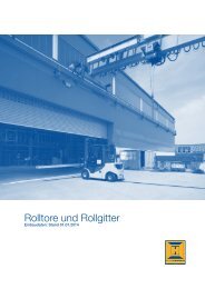
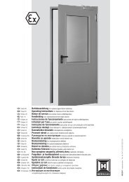
ENGLISHContentsA Items supplied......................................................... 3B Tools needed for assembly of the sliding gateoperator.................................................................... 3C 1 Fitting accessories for plastic toothed tracks...... 4C 2 Plastic toothed track with steel core(fitting bracket at bottom)....................................... 4C 3 Plastic toothed track with steel core(fitting bracket at top)............................................. 4C 4 Galvanised steel toothed track.............................. 4C 5 Fitting accessories for steel toothed tracks......... 4Drilling template.................................................. 1311 About These Instructions..................................... 211.1 Intended use............................................................ 211.2 Further applicable documents................................ 211.3 Warnings used......................................................... 212 Basic Safety Instructions...................................... 212.1 Fitter qualification.................................................... 212.2 General safety instructions...................................... 212.3 Safety instructions for fitting................................... 222.4 Safety instructions for operation............................. 222.5 Safety instructions for maintenance........................ 222.6 Notices on illustrated section.................................. 223 Definitions.............................................................. 224 Fitting...................................................................... 234.1 Pre<strong>para</strong>tion for fitting............................................... 234.2 Fitting the sliding gate operator.............................. 244.2.1 Foundation for the sliding gate operator................. 244.2.2 Establishing the fitting dimensions.......................... 244.2.3 Anchoring the operator........................................... 244.2.4 Opening the operator housing................................ 244.2.5 Fitting the operator housing.................................... 244.3 Fitting the toothed track.......................................... 244.4 Connecting the mains lead...................................... 254.5 Fitting the print bracket........................................... 254.6 Fitting the magnet bracket...................................... 254.7 Locking the operator............................................... 254.8 Electrical connection............................................... 254.9 Connecting standard components.......................... 254.10 Connecting additional components/accessories.... 254.10.1 Connecting an external radio receiver*................... 254.10.2 Connecting external buttons*.................................. 254.10.3 Connecting a cut-out to stop the operator(STOP or emergency OFF circuit)............................ 264.10.4 Connecting a warning lamp*................................... 264.10.5 Connecting safety/protective devices..................... 264.10.6 BUS connection...................................................... 265 Putting into Service............................................... 265.1 General.................................................................... 265.2 Overview of set-up mode........................................ 265.3 Pre<strong>para</strong>tion.............................................................. 265.4 Learning the gate's end-of-travel positions............ 265.4.1 Recording the CLOSE end-of-travel positionvia the limit switch................................................... 275.4.2 Recording the OPEN end-of travel position............ 275.4.3 Recording the partial opening end-of-travelposition.................................................................... 275.4.4 Completion of set-up mode.................................... 275.4.5 Reference cycle....................................................... 275.5 Learning the forces.................................................. 275.6 Changing the starting point for slow speed whenopening and closing................................................ 285.7 Reversal limit........................................................... 285.8 Overview and settings of the DIL switches ............ 285.8.1 DIL switch 1............................................................. 285.8.2 DIL switch 2............................................................. 285.8.3 DIL switch 3/DIL switch 4........................................ 285.8.4 DIL switch 5/DIL switch 6........................................ 295.8.5 DIL switch 7............................................................. 295.8.6 DIL switch 8/DIL switch 9........................................ 295.8.7 DIL switch 10........................................................... 295.8.8 DIL switch 11........................................................... 295.8.9 DIL switch 12........................................................... 296 Hand Transmitter................................................... 306.1 Control elements..................................................... 306.2 Important information for using the handtransmitter............................................................... 306.3 Restoring the factory coding................................... 307 Radio Remote Control.......................................... 307.1 Integral radio receiver.............................................. 307.2 Programming the hand transmitter buttons on anintegral radio receiver.............................................. 317.3 Deleting all data of an integral radio receiver.......... 317.3.1 Connecting an external radio receiver*................... 318 Restoring the Factory Setting of the SlidingGate Operator........................................................ 319 Operation............................................................... 319.1 Behaviour during a power failure............................. 319.2 Behaviour following a power failure........................ 3210 Inspection and Maintenance................................ 3210.1 Operation, error and warning messages................. 3210.1.1 LED GN................................................................... 3210.1.2 LED RD.................................................................... 3210.2 Error acknowledgement.......................................... 3311 Dismantling and Disposal..................................... 3312 Optional Accessories............................................ 3313 Warranty Conditions............................................. 3314 Technical data........................................................ 3315 Overview of DIL Switch Functions....................... 34Illustrated section..............................115-129Dissemination as well as duplication of this document and theuse and communication of its content are prohibited unlessexplicitly permitted. Noncompliance will result in damagecompensation obligations. All rights reserved in the event ofpatent, utility model or design model registration. Subject tochanges.20 TR10A059-C RE / 10.2008
ENGLISH1About These InstructionsDear Customer,We are glad that you have decided on a quality product fromour company.Read through all of the instructions carefully: they containimportant information about the product. Pay attention to andfollow the instructions provided, particularly the safetyinstructions and warnings.Please keep these instructions in a safe place and make surethat they are available to all users at all times.1.1 Intended useThe sliding gate operator is designed and intendedexclusively for the operation of smooth-running sliding gatesin the domestic, non-commercial sector. The maximumpermissible gate length and maximum weight must not beexceeded.Please note the manufacturer's specifications regarding thegate and operator combination. Possible hazards as definedin EN 12604, EN 12605, EN 12445 and EN 12453 areprevented by the design itself and by carrying out fitting inaccordance with our guidelines. Gate systems used by thegeneral public and equipped with a single protective device,e.g. force limit, may only be used when monitored.1.2 Further applicable documentsThe following documents for safe handling and maintenanceof the gate system must be placed at the disposal of the enduser:• These instructions• The enclosed test manual1.3Warnings usedCAUTIONIndicates a danger that can lead to damage or destructionof the product.The general warning symbol indicates a dangerthat can lead too injury or death. In the text section, thegeneral warning symbol will be used in connection with thecaution levels described below. In the illustrated section, anadditional instruction refers back to the explanation in thetext.CAUTIONIndicates a danger that can lead to minor or moderateinjuries.WARNINGIndicates a danger that can lead to death or serious injuries.DANGERIndicates a danger that leads directly to death or seriousinjuries.2 Basic Safety InstructionsPlease pay attention to all our safety and warning notices.Note:The test manual and instructions for safe handlingand maintenance of the gate system must be placed at thedisposal of the end user.2.1 Fitter qualificationFitting, maintenance, repairs, and disassembly of the slidinggate operator must be performed by a specialist. Accordingto EN 12635, a qualified person is a person with suitabletraining, specialist knowledge and practical experiencesufficient to correctly and safely fit, test, and maintain a gatesystem.ff In the event of a failure of the sliding gate operator, aspecialist must be commissioned immediately for theinspection or repair work.2.2General safety instructionsWARNINGDanger of injury due to incorrect fitting and handlingIncorrect fitting or handling of the operator may triggerunwanted gate travel. Persons or objects may be trappedas a result.ff Follow all the instructions provided in this manual.Danger of injury during repairs and adjustment workA malfunction in the gate system or an incorrectly alignedgate can cause serious injuryff Do not use the gate system if repair or adjustmentwork must be conducted.• If you comply with these fitting instructions, as well as thefollowing conditions, you can assume that the operatingforces are complied with according to DIN EN 12453:–– The centre of gravity for the gate must be in thecentre of the gate (maximum permissible deviation± 20%).–– The gate is easy to move and does not have anygradients/slopes (0%).–– A Hörmann DP1 (article no.: 436 288) or DP3 (articleno.: 436 388) sound-absorbing seal is fitted to theclosing edge(s).–– The operator is programmed for a slow speed(Changing the starting point for slow speed whenopening and closing on page 28).–– The reversal limit at 50 mm opening width has beenchecked and maintained over the entire length of themain closing edge.–– The distance between the supporting rollers in selfsupportinggates (maximum width 6200 mm,maximum opening width 4000 mm) is max. 2000 mm.• Before installing the operator and in the interests ofpersonal safety, make sure that any necessary repairs tothe gate are carried out by a qualified service engineer.TR10A059-C RE / 10.2008 21
ENGLISH2.3 Safety instructions for fittingWarningIncorrect attachment of control devicesIncorrectly attached control devices (e.g.buttons) may trigger unwanted gate travel.Persons or objects may be trapped as aresult.ff Fit permanently installed control devices(such as buttons, etc.) within sight of thegate, but away from moving parts.ff Install control devices at a height of atleast 1.5 m (out of the reach of children).Observe the following points during fitting:• The fitter must ensure that the national regulationsgoverning the operation of electrical equipment arecomplied with.• Before fitting the operator, make sure that the gate canalso be easily operated manually. Use on gates with agradient or slope is impermissible.• Prior to installation, immobilize any mechanical locks notneeded for power operation of the sliding gate. Thisincludes in particular any locking mechanisms connectedwith the gate lock.• In addition, check the entire gate system (gate pivots,bearings and fastenings) for wear and possible damage.Check for signs of rust, corrosion or fractures.• The applicable regulations regarding occupational safetymust be complied with when carrying out the fitting work.• Always cover the operator before drilling, since drillingdust and shavings can lead to malfunctions.• After fitting has been completed, the installer of the gatesystem must declare conformity with DIN EN 13241-1 inaccordance with the scope of application.2.4Safety instructions for operation2.5 Safety instructions for maintenance• The sliding gate operator is maintenance-free. For yourown safety, however, we recommend having the gatesystem checked by a specialist in accordance with themanufacturer's specifications.• All safety and protective functions must be checkedmonthly to ensure that they are in working order. Anymalfunctions and/or defects must be rectifiedimmediately if necessary.• Inspection and maintenance may only be carried out by aqualified person. Contact your supplier for this purpose.A visual inspection may be carried out by the owner.• Contact your supplier in the case of necessary repairs.We would like to point out that any repairs not carried outproperly or with due professionalism shall render thewarranty null and void.2.6 Notices on illustrated sectionThe illustrated section shows the operator attached to theinside right of a closed sliding gate. Where installation orprogramming for a sliding gate differs because the operator isattached to the inside left of a closed sliding gate, this isshown in addition.Several figures also contain the symbol below with a textreference. These references to specific texts in the ensuingtext section provide you with important information regardingfitting and operation of the sliding gate operator.Example:2.2See text section, Chapter 2.2In addition, in both the text section and the illustrated sectionat the points where the DIL switches to set the controls areexplained, the following symbol is shown.This symbol indicates the factory setting(s) ofthe DIL switches.WarningDanger of injury during gate travelPersons or objects may be trapped while thegate is closing.ff Make sure that no persons or objects arein the gate's travel range.ff Make sure that children are not playingnear the gate system.3DefinitionsHold-open phaseWaiting phase at the OPEN end-of-travel position before thegate closes during automatic timed closingAutomatic timed closingAutomatic timed closing of the gate after a set time haselapsed and after reaching the OPEN end-of-travel position.DIL switchesSwitches on the control print for setting the control.Through-traffic photocellWhen the gate is passed through, the photocell stops thehold-open phase and resets it to a preset value.Impulse controlA sequence of impulses which allows the gate to alternatelyOPEN-STOP-CLOSE-STOP.22 TR10A059-C RE / 10.2008
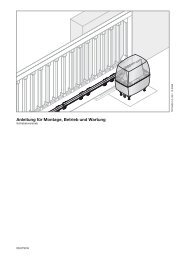
ENGLISHNote:The installer must check that the fitting materials supplied aresuitable for the purpose and intended place of installation.4.2Fitting the sliding gate operator4.2.1 Foundation for the sliding gate operatorff A foundation must be laid for the sliding gate operator asshown in Figure 1a and Figure 1b - the * mark hererepresents the frost-free depth (in Germany = 80 cm).A larger foundation must be laid if using a closing edgesafety device (see Figure 1c/1d).ff A base foundation may be required for gates with insiderollers. The 230/240 V AC mains lead for the sliding gateoperator must be routed through an empty tube in thefoundation. The lead to connect 24 V accessories mustbe installed in a se<strong>para</strong>te tube that is se<strong>para</strong>ted from themains lead (see Figure 1.1).Note:The foundation must have set and dried sufficiently before thefollowing work is carried out!4.2.2 Establishing the fitting dimensions1. Before drilling the four Ø12 mm drill holes, mark theirposition on the surface of the foundation. To do so, usethe drilling template included with these instructions (seeFigure 1.2).2. First select the toothed track to be used from the tablebelow and find the minimum and maximum fittingdimensions (dimensions A).4.2.3Toothed trackDimensions A (mm)Min.Max.438 759 126 138438 631 125 129438 632 129 133Anchoring the operatorff After drilling, check the depth of the drill holes (80 mmdeep) to ensure that the stock screws can be screwed inas far as shown in Figure 1.2.Use the socket wrench included in the scope of deliveryto fit the stock screws in the foundation.4.2.4Opening the operator housingCAUTIONDamage due to moisturePenetrating moisture may damage the control.ff Protect the control from moisture when you open theoperator housing.ff The housing cover must be opened in order to fit thesliding gate operator (see Figure 1.3).4.2.5 Fitting the operator housing1. Release the operator (see Figure 1.4).Note:The motor and pinion are lowered in the housing when theoperator is released.2. Unplug the existing connecting terminals, loosen thefastening screws on the print bracket and completelyremove the print bracket (see Figure 1.5).3. Insert the tube seals from the scope of delivery into theoperator housing (see Figure 1.6). If necessary, cut theseal to fit the tube.4. Insert the provided fitting aid in the socket wrench foreasy installation of screws and nuts.5. When the operator housing is placed on the stockscrews, the mains lead and, if applicable, 24 Vconnecting lead must be pulled into the operator housingthrough the tube seals inserted before.6. Screw down the operator housing (see Figure 1.6 andFigure 1.7).Pay attention that the operator fitting is horizontal, stableand secure.7. Seal the operator housing to protect it from humidity andvermin (see Figure 1.8).4.3Fitting the toothed trackBefore fitting:ff The sliding gate operator must be released before thetoothed tracks are installed (see Figure 1.4).ff Make sure that the required hole depths are availablebefore fitting the toothed tracks.ff To fit the toothed tracks to the sliding gate, use theconnectors (bolts and nuts) from the se<strong>para</strong>tely orderedfitting accessories (see Figure C1 or Figure C5).Note:• Contrary to the illustrated section, use the appropriateconnectors (e.g. for timber gates use woodscrews), aswell as the proper hole depths for other gate types.• Contrary to the illustrated section, the required core holediameter may vary depending on material thickness orstrength. The required diameter may be Ø 5.0-5.5 mm foraluminium and Ø 5.7-5.8 mm for steel.Fitting:CAUTIONDamage caused by dirtDrilling dust and chippings from drilling work can lead tomalfunctions.ff Cover the operator during drilling work.1. For simple assembly of the toothed tracks, fit the plastictoothed wheels into the holes of the toothed wheel cap(see Figure 2.1).2. Place the middle of the toothed track firmly onto bothplastic toothed wheels.3. Mark the position of the holes on the gate.ff When fitting the toothed tracks, make sure that thetransitions between the individual toothed tracks aresmooth to ensure uniform gate movement.ff After fitting, the toothed tracks and the toothed wheel ofthe operator must be aligned to each other. To do so,both the toothed tracks as well as the operator housingcan be adjusted.Incorrectly fitted or poorly aligned toothed tracks maylead to unintentional reversing. It is essential that thespecified dimensions are adhered to!24 TR10A059-C RE / 10.2008
ENGLISH4.4 Connecting the mains leadMains connection is made directly at the plug terminal to thetransformer via the NYY underground cable (see Figure 2.4).Follow the safety instructions in Electrical connection onpage 25.4.5 Fitting the print bracket1. Fasten the print bracket using the two screws loosenedearlier B , as well as two additional screws from thescope of delivery (see Figure 2.5).2. Re-plug the connecting terminals.4.6 Fitting the magnet bracket1. Push the gate by hand into the CLOSE end-of-travelposition.2. Fully preassemble the supplied magnet slide in the centreposition (see Figure 2.6).3. Install the toothed track clip on the toothed track in sucha manner that the magnet is positioned opposite the reedcontact in the print bracket of the operator housing,offset by approx. 20 mm, when the gate is closed.Note:If you are unable to push the gate easily into the requiredCLOSE end-of-travel position, check the gate mechanics foruse with the sliding gate operator (Safety instructions forfitting, page 22).4.7 Locking the operatorff The operator is engaged once locked. The motor mustbe slightly raised when the mechanism is turned to thelock position (see Figure 3).4.8 Electrical connectionDangerDangerous electrical voltageMains voltage is necessary for operating this device.Improper use can cause electrical shocks which can lead todeath or serious injuries.ff Electrical connections may only be made by a qualifiedelectrician.ff Always disconnect the operator from the power supplybefore performing any work on the gate system.ff The on-site electrical installation must comply with therespective safety regulations.ff All the cables must be inserted into the control unitfrom below and free from distortion.4.9 Connecting standard componentsMains connection is made directly at the plug terminal to thetransformer via the NYY underground cable (see Figure 2.4).4.10 Connecting additional components/accessoriesThe total consumed current may be max. 500 mA whenconnecting accessories at the following terminals:• 24 V=• SE3/LS• Ext. radio• SE1/SE24.10.1 Connecting an external radio receiver*ffSee Figure 4.1(*Accessory, not included as standard equipment!)ff The wires of the external radio receiver should beconnected as follows:–– GN to terminal 20 (0 V)–– WH to terminal 21 (channel 1 signal)–– BN to terminal 5 (+24 V)–– YE to terminal 23 (channel 2 signal for partialopening). Only with a 2-channel receiver.Note:The aerial wire of external radio receivers should not comeinto contact with metal objects (nails, bracing, etc.). The bestorientation to achieve an optimum range must be establishedby trial and error. When used at the same time, GSM 900mobile phones can affect the range of the radio remotecontrol.4.10.2 Connecting external buttons*ffSee Figure 4.2(*Accessory, not included as standard equipment!)One or more buttons with normally open contacts (volt-free),e.g. key switches, can be connected in <strong>para</strong>llel, max. leadlength 10 m.Impulse controlffFirst contact to terminal 21ffSecond contact to terminal 20Partial opening:ffFirst contact to terminal 23ffSecond contact to terminal 20Note:If auxiliary voltage is needed for an external button, then avoltage of +24 V DC is available for this at terminal 5 (againstterminal 20 = 0 V).CAUTIONDamage to the electronics caused by external voltageExternal voltage on the connecting terminals of the controlwill destroy the electronics.ff Lay the operator cables in an installation system that isse<strong>para</strong>te from the mains supply.ff If laying cables in the ground, use an undergroundcable (NYY) (see Figure 1).TR10A059-C RE / 10.2008 25
ENGLISH4.10.3Connecting a cut-out to stop the operator(STOP or emergency OFF circuit)A cut-out with normally closed contacts (switching to 0 V orvolt-free) is connected as follows (see Figure 4.3):1. Remove the wire jumper inserted at the factory betweenterminal 12 and terminal 13.–– Terminal 12: STOP or emergency OFF input–– Terminal 13: 0 V, allows normal function of theoperator2. Connect switching output or first contact at terminal 12(STOP or emergency OFF input).3. Connect 0 V (ground) or second contact to terminal 13(0 V).Note:By opening the contact, any travel cycles in progress areimmediately halted and permanently prevented.4.10.4 Connecting a warning lamp*ffSee Figure 4.4(*Accessory, not included as standard equipment!)A warning lamp or CLOSE end-of-travel signal can beconnected via the volt-free contacts on the Option connector.The voltage at the 24 V DC connector can be used foroperation (e.g. warning signals prior to and during gate travel)with a 24 V lamp (max. 7 W).Note:A 230 V warning lamp must be directly supplied with power(see Recording the CLOSE end-of-travel position via the limitswitch, page 27).4.10.5 Connecting safety/protective devicesffSee Figure 4.5-4.7Safety devices such as photocells/closing edge safetydevices (SKS) or 8k2 resistance contact strips can beconnected:SE1SE2SE3In the opening direction, safety device with testingor 8k2 resistance contact strip.In the closing direction, safety device with testing or8k2 resistance contact strip.In the closing direction, photocell without testing ordynamic 2-wire photocell, e.g. as a through-trafficphotocell.The selection for the 3 safety circuits can be set via the DILswitches (see Overview and settings of the DIL switches ,page 28).Terminal 20Terminal 18Terminals 71/72/73Terminal 50 V (voltage supply)Test signalSignal of safety device+24 V (voltage supply)4.10.6 BUS connectionffSee Figure 4.85 Putting into Serviceff Before initial operation, check that all the connectingleads are correctly installed at the connecting terminals.ff Open the gate halfway.ff Engage the operator.5.1 GeneralThe control is programmed via the DIL switches. Changes tothe DIL switch settings are only permissible under thefollowing conditions:• The operator is at a standstill.• The advance warning or hold-open phase is not active.5.2 Overview of set-up modeSet-up mode is described in the following chapters:• Pre<strong>para</strong>tion, page 26• Learning the gate‘s end-of-travel positions, page 26––Recording the CLOSE end-of-travel position via thelimit switch, page 27––Recording the OPEN end-of travel position, page 27––Recording the partial opening end-of-travel position,Page 27• Learning the forces, page 27• Changing the starting point for slow speed when openingand closing, page 28• Reversal limit, page 285.3 Pre<strong>para</strong>tionff All the DIL switches must be in the factory setting, i.e. allthe switches must be at OFF (see Figure 5).Change the following DIL switches:f f DIL switch 1: Installation direction (see Figure 5.1)ON Gate closes to the right(as viewed from the operator)Gate closes to the leftOFF (as viewed from the operator)f f Accordingly set DIL switches 3-7: Safety devices (seeChapter DIL switch 3/DIL switch 4 to DIL switch 7 frompage 28).5.4 Learning the gate's end-of-travel positionsf f DIL switch 2: Set-up mode (see Figure 6.1)ON Learning the gate travelOFFNote:The safety devices are not active during set-up mode.Note:Safety devices without a testing unit (e.g. static photocells)must be tested twice a year. They may only be used toprotect property!26 TR10A059-C RE / 10.2008
ENGLISH5.4.1 Recording the CLOSE end-of-travel position viathe limit switchThe limit switch (reed contact) must be connected beforelearning the end-of-travel positions. The limit switch wiresmust be connected at the REED terminal (see Figure 6.1a).The option relay has the same function as the red LED duringset-up. The limit switch position can be viewed from afar witha connected lamp (see Figure 4.4).Learning the CLOSE end-of-travel position:1. Open the gate a bit.2. Press print button T and keep it pressed.The gate now travels towards CLOSE at slow speed. Thered LED goes out once the limit switch has beenreached.3. Immediately release print button T.The gate is now in the CLOSE end of travel position.Note:If the gate travels in the opening direction, DIL switch 1 is inthe wrong position and must be reset. Then repeat steps 1to 3.If the position of the gate does not correspond to the desiredCLOSE position, a readjustment must be made.Readjusting the CLOSE end-of-travel position:1. Adjust the position of the magnet by moving the magnetslide.2. Press print button T, until the gate reaches the readjustedend-of-travel position and the red LED goes out.3. Repeat this process until the desired end-of-travelposition has been reached.5.4.2 Recording the OPEN end-of travel positionffSee Figure 6.1bLearning the CLOSE end-of-travel position:1. Press print button T and keep it pressed.The gate opens at slow speed.2. Release print button T once the required OPEN end-oftravelposition is reached.3. Press print button P to confirm this position.The green LED flashes rapidly for 2 seconds to indicatethat the OPEN end-of-travel position has been recorded.5.4.3 Recording the partial opening end-of-travelpositionLearning the partial opening end-of-travel position:1. Press print button T and keep it pressed to move thegate back towards the CLOSE position.2. Release print button T once the desired partial openingend-of-travel position is reached.3. Press print button P to confirm this position.The green LED flashes slowly to indicate that the partialopening end-of-travel position has been recorded.5.4.4 Completion of set-up modeffAfter completion of set-up mode, set DIL switch 2(function: learning the gate travel) to OFF.The green LED signals that forces must be learned byflashing quickly (see Figure 6.1c).Note:The safety devices are activated.5.4.5 Reference cycleffSee Figure 6.2After learning the end-of-travel positions, the first cyclethereafter is always a reference cycle. During this referencecycle the option relay clocks and a connected warning lightflashes.Reference cycle to CLOSE end-of-travel position:ffPress print button T once.The operator automatically moves into the CLOSE endof-travelposition.5.5 Learning the forcesOnce the end-of-travel positions have been learned and thereference cycle performed, the forces must be learned. Forthis, three successive gate cycles must take place, duringwhich none of the safety devices may be activated. Recordingthe forces takes place automatically by press-and-releaseoperation (maintained function) in both directions, i.e. once animpulse has been given, the operator causes the gate totravel to the end-of-travel position. The green LED flashesthroughout. This LED is steadily illuminated once the forcelearning cycles have been completed.ff Both of the following procedures must be conductedthree times.Learning the forces to the OPEN end-of-travel position:ffPress print button T once.The operator automatically moves into the OPEN end-oftravelposition.Learning the forces to the CLOSE end-of-travel position:ffPress print button T once.The operator automatically moves into the CLOSE endof-travelposition.Setting the force limit:WARNINGDanger of injury if force limit is too highIf the force limit has been set too high, the gate will not stopon time when closing and may trap persons or objects.ff Do not set a force limit that is too high.Note:Due to special fitting situations, it can, however, happen thatthe previously learned forces prove inadequate which canlead to undesired reversing. Readjust the forces in suchcases.1. A potentiometer is available to set the force limits of thegate when opening and closing; it is identified with KraftF (Force F) on the control print.The increase in the force limit is a percentage increase inrelation to the learned values; in the process, the settingof the potentiometer denotes the following force increase(see Figure 7.1):Full leftCentredRight fitting0% force+15% force+75% forceTR10A059-C RE / 10.2008 27
ENGLISH2. The learned force setting must be checked using asuitable force measuring device to make sure that thevalues are permissible within the application scope of theEuropean Standards EN 12453 and EN 12445 or thecorresponding national regulations.5.6 Changing the starting point for slow speedwhen opening and closingThe slow speed length is automatically set to a basic value ofapprox. 500 mm before the end positions after the endpositions have been learned. The starting point can bereprogrammed from a minimum length of approx. 300 mm upto the entire gate length (see Figure 7.2).Setting the positions for slow speed:1. The end-of-travel positions must be set and the gate is inthe CLOSE end-of-travel position.2. DIL switch 2 must be OFF.3. Set DIL switch 12 to ON to set the starting position forslow speed.4. Press print button T.The gate will travel normally in press-and-releaseoperation towards the OPEN direction.5. When the gate passes the required position for the startof slow speed, briefly press print button P.The gate will move at slow speed for the remainingdistance until in the OPEN end-of-travel position.6. Press print button T again.The gate will again travel normally in press-and-releaseoperation towards the CLOSE direction.7. When the gate passes the required position for the startof slow speed, briefly press print button P.The gate will move at slow speed for the remainingdistance until in the CLOSE end-of-travel position.8. Set DIL switch 12 to OFF.The slow speed starting point settings have now beencompleted.Note:The starting points for slow speed can also be set to"overlap"; in this case, the entire leaf movement is in slowspeed.Changing the starting points for slow speed deletes thealready learned forces. After a change has been made, thegreen LED flashes to signal that the forces must be learnedagain.ff Both of the following procedures must be conductedthree times.Learning the forces to the OPEN end-of-travel position:ffPress print button T once.The operator automatically moves into the OPEN end-oftravelposition.Learning the forces to the CLOSE end-of-travel position:ffPress print button T once.The operator automatically moves into the CLOSE endof-travelposition.5.7 Reversal limitDuring operation of the gate in the CLOSE direction, it mustdifferentiate between two options: whether the gate contactsthe limit stop (gate system stops) or an obstruction (gatereverses direction). The limit range can be adjusted as follows(see Figure 7.3).Setting the reversal limit:1. Set DIL switch 11 to ON.The reversal limit can now be set step-by-step.2. Briefly press print button P to reduce the reversal limit.orBriefly press print button T to increase the reversal limit.During the procedure to learn the reversal limits, thegreen LED displays the following settings:1x flashingto10x flashingMinimum reversal limit, the green LEDflashes onceMaximum reversal limit, the green LEDflashes max. 10 times3. Set DIL switch 11 back to OFF to store the set reversallimit.5.8 Overview and settings of the DIL switchesChanges to the DIL switch settings are only permissible underthe following conditions:• The operator is at a standstill.• The advance warning or hold-open phase is not active.The DIL switches must be set as described below inaccordance with national regulations, the desired safetydevices and the on-site circumstances.5.8.1DIL switch 1Installation direction:ffSee Chapter Pre<strong>para</strong>tion, page 265.8.2DIL switch 2Installation direction:ffSee Chapter Learning the gate‘s end-of-travel positions,page 265.8.3 DIL switch 3/DIL switch 4SE 1 safety device (opening):ffSee Figure 7.4The functions of the safety device are set with DIL switch 3 incombination with DIL switch 4.3 ON Activation kit for closing edge safety device orphotocell with testing3 OFF • 8k2 resistance contact strip• No safety device (8k2 resistance betweenterminals 20/72, delivery status)4 ON Brief, delayed reversing in the CLOSE direction(for photocell)4 OFF Brief, immediate reversing in the CLOSE direction(for SKS)28 TR10A059-C RE / 10.2008
ENGLISH5.8.4DIL switch 5/DIL switch 6ffSee Figure 7.7cSE 2 safety device (closing):ffSee Figure 7.5The functions of the safety device are set with DIL switch 5 incombination with DIL switch 6.5 ON Activation kit for closing edge safety device orphotocell with testing5 OFF • 8k2 resistance contact strip• No safety device (8k2 resistance betweenterminals 20/73, delivery status)6 ON Brief, delayed reversing in the OPEN direction (forphotocell)6 OFF Brief, immediate reversing in the OPEN direction(for SKS)8 ON 9 OFF OperatorAdvance warning phase for every gatetravel without automatic timed closingOption relayRelay clocks rapidly during theadvance warning phase, normallyduring the travel phase.ffSee Figure 7.7d8 OFF 9 OFF OperatorNo special functionOption relayRelay picks up in the CLOSE end-oftravelposition.5.8.5 DIL switch 7SE 3 protective device (closing):ffSee Figure 7.6Delayed reversing to CLOSE end-of-travel position.7 ON Dynamic 2-wire photocell7 OFF • Static photocell without testing• No safety device (wire jumper betweenterminals 20/71, delivery status)5.8.6 DIL switch 8/DIL switch 9The functions of the operator (automatic timed closing/warning phase) and the function of the option relay are setwith DIL switch 8 in combination with DIL switch 9.ffSee Figure 7.7a8 ON 9 ON OperatorAutomatic timed closing, advancewarning phase for each gate movementOption relayRelay clocks rapidly during the advancewarning phase, normally during the travelphase and is OFF during the hold-openphase.ffSee Figure 7.7b8 OFF 9 ON OperatorAutomatic timed closing, advancewarning phase only for automatic timedclosingOption relayRelay clocks rapidly during the advancewarning phase, normally during the travelphase and is OFF during the hold-openphase.Note:Automatic timed closing is only possible from the determinedend-of-travel positions (full or partial opening). Automatictimed closing is deactivated if it fails three times. The operatormust be restarted with an impulse.5.8.7DIL switch 10Effect of the SE 3 protective device as a through-trafficphotocell with automatic timed closingffSee Figure 7.8This switch is used to set the SE3 protective device as athrough-traffic photocell with automatic timed closing.7 ON The photocell is activated as a through-trafficphotocell, after the photocell has been passed,the hold-open phase is reduced.7 OFF The photocell is not activated as a throughtrafficphotocell. If, however, automatic timedclosing is activated and the photocellinterrupted after the hold-open phase haselapsed, the hold-open phase will be reset tothe preset time.5.8.8DIL switch 11Setting up the reversal limitsffSee Chapter Reversal limit, page 285.8.9DIL switch 12Starting point for slow speed when opening and closing:ffSee Chapter Changing the starting point for slow speedwhen opening and closing, page 28TR10A059-C RE / 10.2008 29
ENGLISH66.1ffSee Figure 8Hand TransmitterControl elements1 LED2 Control buttons3 Battery compartment cover4 Battery5 Reset button6 Hand transmitter holder6.2Important information for using the handtransmitter• Only use original components when putting the remotecontrol into service.• If there is no se<strong>para</strong>te garage entrance, perform allprogramming changes and extensions while standing inthe garage.• After programming or extending the remote control,check the functions.• Hand transmitters should be kept away from children andmay only be used by people who have been instructedon how the remote-control gate functions!• The hand transmitter may only be used if the gate is insight!• Remote-control door/gate systems can only be driven orpassed through if the garage door/gate is in the OPENend-of-travel position!• Protect the hand transmitter from the followingenvironmental conditions:–– Direct sunlight (perm. ambient temperature: –20°C to+60°C)–– Moisture–– DustThese conditions can impair function!CautionUnwanted gate travelUnwanted gate travel may occur while programming thehand transmitter.ff When programming and extending the remote control,make sure no persons or objects are within the gate’srange of travel.Note:Local conditions may affect the useful range of the remotecontrol.6.3 Restoring the factory codingffSee Figure 8Note:The following steps are only required in the case ofinadvertent extension or learning processes.The code space for each button on the hand transmitter canbe assigned the original factory coding or another code.1. Open the battery compartment cover.A small button is visible on the print.CAUTIONDestruction of the buttonff Do not use any pointed objects or excessive force whenpressing the button.2. Carefully press button 5 with a blunt object and keep itpressed.3. Press the control button to be coded and keep itpressed.The transmitter LED will flash slowly.4. If you keep the small button pressed until the slowflashing stops, the control button will be assigned theoriginal factory coding and the LED will start to flashfaster.5. Close the battery compartment cover.6. Reprogram the receiver.7 Radio Remote Control7.1 Integral radio receiverThe sliding gate operator is equipped with an integral radioreceiver. With the integral radio receiver, the impulse (OPEN-STOP-CLOSE-STOP) and partial opening functions can eachbe programmed for max. 12 different hand transmitterbuttons. If more than 12 hand transmitter buttons areprogrammed, the first one programmed will be deletedwithout advance warning. All memory spaces are empty in thedelivery condition.Radio programming/deleting data is only possible if:• No set-up mode is activated ( DIL switch 2 at OFF).• The leaves are not moving.• No advance warning or hold-open phase is presentlyactive.Note:One of the hand transmitter buttons must be programmed onan integral radio receiver to actuate the operator via radio.There must be a distance of at least 1 m between the handtransmitter and the operator. When used at the same time,GSM 900 mobile phones can affect the range of the radioremote control.30 TR10A059-C RE / 10.2008
ENGLISH7.2 Programming the hand transmitter buttons onan integral radio receiver1. Briefly press print button P once (for channel 1 = impulsecommand) or twice (for channel 2 = partial openingcommand).Pressing circuit board button P again will immediatelyend radio programming.Depending on the channel being programmed, the redLED will flash 1x (for channel 1) or 2x (for channel 2).During this time, a hand transmitter button can beprogrammed for the desired function.2. Press the hand transmitter button to be programmeduntil the red LED on the print flashes rapidly.The code for this hand transmitter button is now stored inthe integral radio receiver (see Figure 9).7.3 Deleting all data of an integral radio receiverffPress print button P and keep it pressed.The red LED flashes slowly, signalling the readiness fordeletion. The flashing rhythm becomes more rapid.Afterwards, the programmed radio codes of all handtransmitters are deleted.7.3.1 Connecting an external radio receiver*(*Accessory, not included as standard equipment!)Instead of an integral radio receiver, an external radio receivercan be used for the impulse or partial opening functions tocontrol the sliding gate operator. Insert the plug of the receiverin the corresponding slot (see Figure 4.1). To avoid doubleassignments, delete the data of the integral radio receiverwhen using an external radio receiver (see Deleting all data ofan integral radio receiver, page 31).8Restoring the Factory Setting of theSliding Gate OperatorResetting the control (learned end-of-travel positions,forces):1. Set DIL switch 2 to ON.2. Immediately press print button P briefly.3. When the red LED flashes rapidly, DIL switch 2 must bequickly set to OFF.The control system has now been reset to the factorysetting.9OperationWARNINGDanger of injury during operationPersons or objects may be trapped while the gate isclosing.ff Only operate the sliding gate operator if you can seethe gate's area of travel!ff Before driving in or out of the gateway, always checkthat the gate has fully opened. Never drive or walkthrough gateways unless the entrance gate hasreached the OPEN end-of-travel position.Danger of crushing and shearingFingers or limbs may be crushed and severed if caught inthe toothed track or between the gate and closing edgewhile the gate is in motion.ff Whenever the gate is moving, never touch the toothedtrack, toothed wheel, and the main or secondaryclosing edges.Before operation:ff All persons using the gate systemmust be shown how to operate itproperly and safely.ff Demonstrate and test themechanical release as well as thesafety return. To do this, halt theclosing gate by grasping it withboth hands.The gate system must initiate thesafety return.The control is set for normal operation.ffPress print button T, the external button or activateimpulse 1.The gate moves in impulse sequence mode (OPEN-STOP-CLOSE-STOP).On activating impulse 2, the gate opens partially (seeFigure 4.1/4.2/9b).9.1 Behaviour during a power failureTo be able to open or close the sliding gate during a powerfailure, it must be disengaged from the operator.Caution!Damage due to moistureff Protect the control from moisture when you open theoperator housing1. Open the housing cover as in Figure 1.3.2. Release the operator by turning the locking mechanism.When releasing the operator, the motor and toothedwheel may have to be pressed downwards to lower themin the housing (see Figure 11.1).The gate can then be opened and closed by hand.TR10A059-C RE / 10.2008 31
ENGLISH9.2 Behaviour following a power failureOnce the power supply has been restored, the gate must bereengaged with the operator upstream from the limit switch.ff Slightly lift the motor when turning the mechanism to thelock position (see Figure 11.2).A necessary reference run following a power failure isautomatically performed if an impulse command ispending.During this reference cycle the option relay clocks and aconnected warning light flashes slowly.10 Inspection and MaintenanceThe sliding gate operator is maintenance-free. The gatesystem must be checked by a specialist in accordance withthe manufacturer's specifications.Note:• Inspection and maintenance may only be carried out by aqualified person. Contact your supplier for this purpose.• A visual inspection may be carried out by the owner. Ifrepairs become necessary, please contact your supplier.We would like to point out that any repairs not carried outproperly or with due professionalism shall render thewarranty null and void.• Check the function of the 8k2 resistance contact stripstwice a year.10.1Operation, error and warning messages10.1.1 LED GNThe green LED (Figure 4) indicates the operating state of thecontrol:Steady illuminationNormal state, all OPEN end-of-travel positions and forceslearned.Fast flashingForce learning cycles must be performed.Slow flashingSet-up mode – end-of-travel settingWhen setting up the reversal limits(see Reversal limit, page 28)• Flashing frequency is proportional to the selectedreversal limit• Minimum reversal limit: LED is permanently off• Maximum reversal limit: LED is permanently on10.1.2 LED RDThe red LED (Figure 4.1) indicates:In set-up mode• Limit switch actuated = LED is on• Limit switch not actuated = LED is offRadio programming displayFlashing as described in Programming the hand transmitterbuttons on an integral radio receiver on page 31Display of the button inputs, radio• Actuated = LED is on• Not actuated = LED is offIn normal operation:Flashing code as an error/diagnosis displayError/diagnosis displayThe red LED RD helps to easily identify causes whenoperation does not go according to plan.Display flashes 2xError/warningSafety/protective device has respondedPossible cause• Safety/protective device has been actuated• Safety/protective device defective• Without the SE1, 8k2 resistance between terminal 20and 72 missing• Without the SE2, 8k2 resistance between terminal 20and 73 missing• Without the SE3, wire jumper between terminal 20 and71 missingRemedy• Check safety/protective device• Check whether the appropriate resistance/wirejumpers are present without the connected safety/protective deviceDisplay flashes 3xError/warningForce limit in CLOSE directionPossible causeObstruction in gate areaRemedyRemove obstruction; check forces, if necessary, increaseDisplay flashes 4xError/warningHold or static current circuit is open, operator at a standstillPossible cause• Normally closed contact at terminal 12/13 is open• Electric circuit interruptedRemedy• Close contact• Check electric circuitDisplay flashes 5xError/warningForce limit in OPEN directionPossible causeObstruction in gate areaRemedyRemove obstruction; check forces, if necessary, increaseDisplay flashes 6xError/warningSystem errorPossible causeInternal errorRemedyRestore the factory setting (see Radio Remote Control,page 30), repeat the learning procedure for the controlsystem and replace, if necessary32 TR10A059-C RE / 10.2008
ENGLISH10.2 Error acknowledgementIf an error occurs, this can be acknowledged, provided theerror is no longer present.ff On pressing the internal or external impulse generator,the error is deleted and the gate travels in thecorresponding direction.11 Dismantling and DisposalHave the sliding gate operator dismantled and disposed of bya specialist.12 Optional AccessoriesOptional accessories are not included in the scope of delivery.Loading of the operator by all electrical accessories: max.100 mA.The following accessories are available:• External radio receivers• External impulse button, e.g. key switch• External code and transponder switches• One-way photocell• Warning lamp/warning light• Photocell expander13Warranty ConditionsWarrantyWe shall be exempt from our warranty obligations andproduct liability in the event that the customer carries out hisown structural alterations or undertakes improper installationwork or arranges for same to be carried out by others withoutour prior approval and contrary to the installation guidelineswe have provided. Moreover, we shall accept no responsibilityfor the inadvertent or negligent use of the operator orimproper maintenance of the gate and the accessories nor fora non-authorized method of installing the gate. Batteries arealso not covered by the warranty.Warranty periodIn addition to the statutory warranty provided by the dealer inthe sales contract, we grant the following warranty for partsfrom the date of purchase:• 5 years for the operator mechanics, motor, and motorcontrol• 2 years on radio equipment, impulse generator,accessories and special systemsThere is no warranty on consumables (e.g. fuses, batteries,lamps). Claims made under the warranty do not extend thewarranty period. For replacement parts and repairs thewarranty period is six months or at least the remainder of thewarranty period.PrerequisitesA claim under this warranty is only valid for the country inwhich the equipment was bought. The product must havebeen purchased through our authorised distribution channels.A claim under this warranty exists only for damage to theobject of the contract itself. Reimbursement of expenditurefor dismantling and installation, testing of correspondingparts, as well as demands for lost profits and compensationfor damages, are excluded from the warranty. The receipt ofpurchase substantiates your right to claim under the warranty.PerformanceFor the duration of the warranty we shall eliminate anyproduct defects that are proven to be attributable to amaterial or manufacturing fault. We pledge to replace free ofcharge and at our discretion the defective goods with nondefectivegoods, to carry out repairs, or to grant a pricereduction.Damages caused by the following are excluded:• improper fitting and connection,• improper initial start-up and operation,• external factors such as fire, water, abnormalenvironmental conditions,• mechanical damage caused by accidents, falls, impacts,• negligent or intentional destruction,• normal wear or deficient maintenance,• repairs conducted by unqualified persons,• use of non-original parts,• removal or defacing of the type plateReplaced parts become our property.14Max. gate width:Max. gate height:Max. gate weight:Technical dataRated load:Max. pull and push force:Operator housing:Mains voltage:Control:Operating mode:Temperature range:Travel/force limit:Automatic safety cut-out:Hold-open phase:Motor:Radio remote control:6,000 mm/8,000 mmdepending on operator type2,000 mm300 kg/500 kg depending onoperator typeSee type plateSee type plateDie-cast zinc and weatherresistant,glass-fibre reinforcedplasticRated voltage 230 V/50 HzMax. power input 0.15 kWMicroprocessor controlsystem, programmable via 12DIL switches, control voltage24 V DCS2, short-time duty 4 minutes-20°C to +60°CElectronicForce limit for both operationaldirections, self-programmingand testing• 60 seconds (photocellrequired)• 5 seconds (shorter holdopenphase with throughtrafficphotocell)Spindle unit with 24 V DCmotor and worm gears,protection category IP 442-channel receiver,hand transmitterTR10A059-C RE / 10.2008 33
ENGLISH15DIL 1ONOFFOverview of DIL Switch FunctionsInstallation directionGate closes to the right (as viewed from the operator)Gate closes to the left (as viewed from the operator)DIL 2ONOFFSet-up modeSet-up mode (limit switch and OPEN end-of-travel position)/delete gate data (reset)Normal operation in press-and-release operationDIL 3 Type of SE1 safety device (connection tml. 72) when openingON Safety device with testing (SKS activating kit or photocell)OFF 8k2 resistance contact strip or none (8k2 resistance between tml. 72 and 20)DIL 4ONOFFEffect of SE1 safety device (connection tml. 72) when openingSE1 activation triggers brief, delayed reversing (for photocell)SE1 activation triggers brief, immediate reversing (for SKS)DIL 5 Type of SE2 safety device (connection tml. 73) when closingON Safety device with testing (SKS activating kit or photocell)OFF 8k2 resistance contact strip or none (8k2 resistance between tml. 73 and 20)DIL 6ONOFFEffect of SE2 safety device (connection tml. 73) when closingSE2 activation triggers brief, delayed reversing (for photocell)SE2 activation triggers brief, immediate reversing (for SKS)DIL 7ONOFFType and effect of SE3 protective device (connection tml. 71) when closingSE3 protective device is a dynamic 2-wire photocellSE3 protective device is a non-tested, static photocellDIL 8 DIL 9 Operator function Option relay functionON ON Automatic timed closing, advance warning phasefor each gate movementOFF ON Automatic timed closing, advance warning phaseonly for automatic timed closingON OFF Advance warning phase for each gate movementwithout automatic timed closingClocks rapidly during advance warning phase,normally during travel phase, is OFF during holdopenphaseClocks rapidly during advance warning phase,normally during travel phase, is OFF during holdopenphaseClocks rapidly during advance warning phase,normally during travel phaseOFF OFF No special function Picks up in the CLOSE end-of-travel positionDIL 10ONOFFThrough-traffic photocell with automatic timed closingSE3 protective device activated as through-traffic photocellSE3 protective device not activated as through-traffic photocellDIL 11ONOFFSet reversal limitReversal limit set step-by-stepNormal operation without functionDIL 12ONOFFSetting the slow speed starting point for opening and closingStarting points for slow speed when opening and closingNormal operation without function34 TR10A059-C RE / 10.2008
FRANÇAISTable des matièresA Articles fournis......................................................... 3B Outils nécessaires au montage de lamotorisation de portail coulissant......................... 3C 1 Accessoires de montage pour les crémaillèresen matière synthétique........................................... 4C 2 Crémaillère synthétique avec noyau en acier(patte de fixation de montage au-dessous).......... 4C 3 Crémaillère synthétique avec noyau en acier(patte de fixation de montage au-dessus)............ 4C 4 Crémaillère en acier galvanisé............................... 4C 5 Accessoires de montage pour crémaillères enacier.......................................................................... 4Gabarit de perçage.............................................. 1311 A propos de ce mode d’emploi............................ 361.1 Utilisation appropriée.............................................. 361.2 Documents valables................................................ 361.3 Consignes de sécurité utilisées............................... 362 Consignes de sécurité importantes..................... 362.1 Qualification du monteur......................................... 362.2 Consignes de sécurité générales............................ 362.3 Consignes de sécurité concernant le montage....... 372.4 Consignes de sécurité concernant lefonctionnement....................................................... 372.5 Consignes de sécurité concernant l’entretien......... 372.6 Remarques concernant la partie illustrée................ 373 Définitions.............................................................. 384 Montage................................................................. 384.1 Pré<strong>para</strong>tion du montage.......................................... 384.2 Montage de la motorisation pour portailcoulissant................................................................ 394.2.1 Fondations de la motorisation pour portailcoulissant................................................................ 394.2.2 Calcul des cotes de montage................................. 394.2.3 Ancrage de la motorisation..................................... 394.2.4 Ouverture du boîtier de motorisation...................... 394.2.5 Montage du boîtier de motorisation........................ 394.3 Montage de la crémaillère....................................... 404.4 Raccordement du câble d’alimentation secteur..... 404.5 Montage du support de platine............................... 404.6 Montage du support magnétique............................ 404.7 Verrouillage de la motorisation................................ 404.8 Raccordement électrique........................................ 404.9 Raccordement de composants standards.............. 404.10 Raccordement de composants supplémentaires /d’accessoires.......................................................... 404.10.1 Raccordement d’un récepteur radio externe*......... 414.10.2 Raccordement d’un bouton-poussoir externe*....... 414.10.3 Raccordement d’un interrupteur pour l’arrêt de lamotorisation (circuit d’arrêt ou circuit d’arrêtd’urgence)................................................................ 414.10.4 Raccordement d’une lampe d’avertissement*........ 414.10.5 Raccordement de dispositifs de sécurité / deprotection................................................................ 414.10.6 Raccordement BUS................................................ 415 Mise en service...................................................... 415.1 Généralités.............................................................. 415.2 Aperçu du service de réglage.................................. 425.3 Pré<strong>para</strong>tion.............................................................. 425.4 Apprentissage des positions finales de portail........ 425.4.1 Détection de la position finale Fermé parl’interrupteur de fin de course................................. 425.4.2 Détection de la position finale Ouvert..................... 425.4.3 Détection de la position finale Ouverture partielle.. 425.4.4 Fin du service de réglage........................................ 425.4.5 Trajet de référence................................................... 425.5 Apprentissage de l’effort......................................... 435.6 Modifier les points de départ de la marche lentelors de l’ouverture et de la fermeture...................... 435.7 Limite d’inversion.................................................... 435.8 Aperçu et réglages des commutateurs DIL............. 445.8.1 Commutateur DIL 1................................................. 445.8.2 Commutateur DIL 2................................................. 445.8.3 Commutateur DIL 3 / Commutateur DIL 4.............. 445.8.4 Commutateur DIL 5 / Commutateur DIL 6.............. 445.8.5 Commutateur DIL 7................................................. 445.8.6 Commutateur DIL 8 / Commutateur DIL 9.............. 445.8.7 Commutateur DIL 10............................................... 455.8.8 Commutateur DIL 11............................................... 455.8.9 Commutateur DIL 12............................................... 456 Emetteur................................................................. 456.1 Eléments de commande......................................... 456.2 Remarques importantes pour l’utilisation del’émetteur................................................................ 456.3 Réinitialisation du code à l’état d’usine................... 467 Télécommande radio............................................. 467.1 Récepteur radio intégré........................................... 467.2 Programmer les boutons de l’émetteur sur unrécepteur radio intégré............................................ 467.3 Suppression de toutes les données d’unrécepteur radio intégré............................................ 467.3.1 Raccordement d’un récepteur radio externe*......... 468 Réinitialiser la motorisation pour portailcoulissant au <strong>para</strong>mètre d’usine.......................... 469 Fonctionnement..................................................... 479.1 Comportement lors d’une panne de secteur.......... 479.2 Comportement après une panne de secteur.......... 4710 Inspection et maintenance................................... 4710.1 Messages de service, d’erreur etd’avertissement....................................................... 4710.1.1 DEL GN................................................................... 4710.1.2 DEL RT.................................................................... 4810.2 Dépannage.............................................................. 4811 Démontage et élimination des déchets............... 4812 Accessoires optionnels......................................... 4813 Obligations de garantie......................................... 4914 Données techniques............................................. 4915 Aperçu des fonctions des commutateurs DIL.... 50Partie illustrée....................................115-129Toute transmission ou reproduction de ce document, touteexploitation ou communication de son contenu sontinterdites, sauf autorisation expresse. Tout manquement àcette règle est illicite et expose son auteur au versement dedommages et intérêts. Tous droits réservés en cas de dépôtd’un brevet, d’un modèle d’utilité ou d’agrément. Sousréserve de modifications.TR10A059-C RE / 10.2008 35
FRANÇAIS1A propos de ce mode d’emploiChère cliente, cher client,Nous vous remercions d’avoir opté pour un produit de qualitéde la société Hörmann.Lisez entièrement et attentivement les présentes instructions:elles contiennent d’importantes informations concernant ceproduit. Veuillez tenir compte des remarques et respecter enparticulier toutes les consignes de sécurité et de danger.Conservez précieusement les présentes instructions etassurez-vous que tous les utilisateurs puissent les consulter àtout moment.1.1 Utilisation appropriéeLa motorisation pour portail coulissant est exclusivementdestinée à l’exploitation de portails coulissants à déplacementaisé, dans le cadre d’un usage privé/non professionnel. Leslimites dimensionnelles et pondérales maximales du portail nedoivent être en aucun cas dépassées.Concernant la combinaison portail / motorisation, veuilleztenir compte des indications du fabricant. Une construction etun montage, conformes à nos directives, permettent d’éviterles dangers potentiels, mentionnés dans les normesEN 12604, EN 12605, EN 12445 et EN 12453. Les installationsde portail qui se trouvent dans les lieux publics et ne sontéquipées que d’un seul dispositif de protection, tel qu’unlimiteur d’effort, ne peuvent être utilisées que soussurveillance.1.2 Documents valablesAfin de garantir une utilisation et un entretien sûrs del’installation de portail, les documents suivants doivent êtremis à la disposition de l’utilisateur final:• Présentes instructions• Carnet d’essai joint1.3Consignes de sécurité utiliséesATTENTIONDésigne un danger susceptible d’endommager ou dedétruire le produit.Ce symbole général d’avertissement désigneun danger susceptible de causer des blessures graves oula mort. Dans la partie texte, le symbole générald’avertissement est utilisé en association avec les degrésde danger décrits ci-dessous. Dans la partie illustrée, uneindication supplémentaire renvoie aux explications du texte.ATTENTIONDésigne un danger susceptible de provoquer des blessureslégères à moyennes.AVERTISSEMENTDésigne un danger susceptible de provoquer la mort ou desblessures graves.DANGERDésigne un danger provoquant immanquablement la mortou des blessures graves indirectes.2 Consignes de sécurité importantesVeuillez respecter toutes nos consignes de sécurité et dedanger.Remarque:Le carnet d’essai et les instructions garantissant la fiabilitéd’utilisation et d’entretien de l’installation de portail doiventêtre mis à la disposition de l’utilisateur final.2.1 Qualification du monteurLe montage, l’entretien, la ré<strong>para</strong>tion et le démontage de lamotorisation de portail coulissant doivent être confiés à unprofessionnel. Conformément à la norme EN 12635, unprofessionnel est une personne qualifiée qui dispose de laformation appropriée, des connaissances spécifiques et del’expérience nécessaires pour un montage, une inspection etune maintenance corrects et sûrs d’une installation de portail.ff En cas de défaillance de la motorisation de portailcoulissant, il convient de confier directement lavérification/ré<strong>para</strong>tion à un professionnel.2.2Consignes de sécurité généralesAVERTISSEMENTRisque de blessures en cas de montage ou demanœuvre incorrectsUn montage ou une manœuvre incorrects de lamotorisation sont susceptibles de provoquer desmouvements de portail involontaire. Le cas échéant, despersonnes ou des objets peuvent être coincés.ff Suivez toutes les consignes des présentes instructions.Risque de blessures lors des travaux de ré<strong>para</strong>tion etde réglageUne défaillance de l’installation de portail ou un portail malréglé peuvent entraîner des blessures gravesff L’installation de portail ne doit pas être utilisée lorsquecelle-ci requiert des travaux de ré<strong>para</strong>tion ou deréglage.• Si la présente notice de montage ainsi que les conditionssuivantes sont respectées, les forces de service devraienten principe être conformes à la norme DIN EN 12453:–– Le centre de gravité du portail doit être situé au milieudu portail (écart maximal autorisé ± 20%).–– Le déplacement du trajet de portail est aisé et cedernier n’est aucunement en pente ou en montée(0 %)–– Le profil d’amortissement Hörmann DP1 (n° d’article:436 288) ou DP3 (n° d’article: 436 388) est monté surle ou les côté(s) de fermeture.–– La motorisation est programmée sur une vitesse lente(voir Modifier les points de départ de la marche lentelors de l’ouverture et de la fermeture à la page 43).–– A une largeur d’ouverture de 50 mm, la limited’inversion est contrôlée et observée sur toute lalongueur de la sécurité de contact principale.–– Pour les portails autoportants (largeur maximale6200 mm, largeur d’ouverture maximale 4000 mm),l’écart entre les rouleaux porteurs est au maximum de2000 mm.• Pour votre propre sécurité, faites impérativement réaliserles éventuels travaux de ré<strong>para</strong>tion par un service aprèsventequalifié, avant d’installer la motorisation.36 TR10A059-C RE / 10.2008
FRANÇAIS2.3 Consignes de sécurité concernant le montageAvertissementMontage incorrect d’appareils decommandeDes appareils de commande (tels que descontacteurs) mal montés peuvent déclencherdes mouvements de portail involontairessusceptibles de coincer des personnes oudes objets.ff Les appareils de commande fixes (telsque les boutons-poussoirs, etc.) doiventêtre montés dans le champ visuel duportail, tout en étant cependant situésloin des pièces mobiles.ff Montez les appareils de commande à unehauteur minimale de 1,5 m (hors deportée des enfants).A respecter lors du montage:• Le monteur doit s’assurer que les prescriptionsnationales en matière d’utilisation des appareilsélectriques sont respectées.• Avant le montage de la motorisation, assurez-vous que leportail est facile à actionner manuellement. L’utilisationsur des portails situés en pente ou en montée n’est pasautorisée !• Avant le montage, mettez hors service tous lesverrouillages mécaniques du portail non utilisés pourl’actionnement d’une motorisation de portail coulissant. Ils’agit tout particulièrement des mécanismes deverrouillage du verrou du portail.• L’installation de portail doit être contrôlée dans sonensemble (pièces articulées, paliers du portail et piècesde fixation) quant à l’usure ou à d’éventuels dommages.Vérifiez qu’il n’y a pas de traces de rouille, de corrosionou de fissures.• Lors de l’exécution des travaux de montage, lesprescriptions en vigueur en matière de sécurité au travail,doivent être respectées.• Lors des travaux de forage, couvrez la motorisation, carla poussière de forage et les copeaux sont susceptiblesd’entraîner des dysfonctionnements.• Après montage, l’installateur est tenu de procéder à unedéclaration de conformité de l’installation, selon la normeeuropéenne DIN EN 13241-1, conformément au domained’application.2.4Consignes de sécurité concernant lefonctionnementAvertissementRisque de blessures lors de mouvement deportailLors de la fermeture du portail, des personnesou des objets peuvent se coincer.ff Assurez-vous qu’aucune personne etqu’aucun objet ne se trouve dans la zonede déplacement du portail.ff Assurez-vous qu’aucun enfant ne joueprès de l’installation de portail.2.5 Consignes de sécurité concernant l’entretien• La motorisation pour portail coulissant ne nécessiteaucun entretien. Pour votre propre sécurité, nous vousrecommandons cependant de faire contrôlerl’installation de portail par un professionnel,conformément aux indications du fabricant.• Toutes les fonctions de sécurité et de protection doiventêtre vérifiées mensuellement quant à leur bonfonctionnement. Si nécessaire, remédiez immédiatementaux défaillances ou défauts.• L’inspection et la maintenance ne doivent être effectuéesque par un professionnel. Pour cela, adressez-vous àvotre fournisseur. L’exploitant peut cependant procéderau contrôle visuel.• Si des ré<strong>para</strong>tions s’avèrent nécessaires, adressez-vousà vos fournisseurs. Nous déclinons toute responsabilitéen cas de ré<strong>para</strong>tions mal ou non effectuées.2.6 Remarques concernant la partie illustréeLes illustrations présentent le montage d’une motorisationsituée à l’intérieur droit d’un portail coulissant fermé. Lesvariations de montage et de programmation, induites par lemontage d’une motorisation à l’intérieur gauche d’un portailcoulissant fermé, sont également présentées.Certaines illustrations sont également accompagnées dusymbole ci-dessous et d’un renvoi. Les textes correspondantà ces renvois contiennent des informations essentielles aumontage et à l’exploitation de la motorisation pour portailcoulissant.Exemple:2.2Voir partie texte, chapitre 2.2De surcroît, le symbole suivant ap<strong>para</strong>ît aussi bien dans lapartie illustrée que dans la partie texte, à tous les endroits oùse trouve une explication au sujet des commutateurs DILpermettant de régler la commande.Ce symbole signale la/les réglage(s) d’usinedes commutateurs DIL.TR10A059-C RE / 10.2008 37
FRANÇAIS3DéfinitionsTemps d’ouvertureTemps d’attente avant la fermeture du portail en positionfinale Ouvert en cas de fermeture automatique.Fermeture automatiqueFermeture automatique du portail après un certain tempsdepuis la position finale Ouvert.Commutateurs DILCommutateurs placés sur la platine de commande et destinésau réglage de la commande.Cellule photoélectrique de passageAprès passage du portail et de la cellule photoélectrique, letemps d’ouverture est interrompu et réinitialisé à une valeurpréréglée.Commande à impulsionCommande qui amène le portail alternativement en positionouverture - arrêt - fermeture - arrêt par une suite d’impulsions.Trajet d’apprentissage de l’effortTrajet d’apprentissage permettant d’apprendre l’effort requispour le déplacement du portail.Trajet normalMouvement de portail suivant les trajets et les effortsenseignés.Trajet de référenceTrajet du portail dans le sens de la position finale Fermépermettant de déterminer la position initiale.Trajet d’inversionDéplacement du portail dans le sens inverse, suite audéclenchement des dispositifs de sécurité.Limite d’inversionLa limite d’inversion définit la plage entre le trajet d’inversionet l’arrêt du portail en cas de coupure d’effort en positionfinale Fermé.Marche lenteLa zone dans laquelle le portail se déplace très lentement afind’atteindre la position finale en douceur.Ouverture partielleDéplacement requis pour le passage de personnes.Trajet d’homme-mortTrajet du portail qui ne se poursuit que tant que les boutonspoussoirscorrespondants sont actionnés.Ouverture intégraleDéplacement requis pour l’ouverture intégrale du portail.Temps d’avertissementDélai entre l’instruction de démarrage (impulsion) et le débutdu trajet du portail.Codes de couleur pour câbles, conducteurs etcomposantsLes abréviations des couleurs pour l’identification des câbles,des conducteurs et des composants sont conformes auxcodes internationaux de couleurs, selon la norme IEC 757:4BK Noir PK RoseBN Marron RD RougeBU Bleu SR ArgentGD Or TQ TurquoiseGN Vert VT VioletGN/YE Vert/jaune WH BlancGY Gris YE JauneOG4.1OrangeMontagePré<strong>para</strong>tion du montageAVERTISSEMENTRisque de blessures en raison d’éléments deconstruction endommagésL’installation de portail ne doit pas être utilisée lorsquecelle-ci requiert des travaux de ré<strong>para</strong>tion ou de réglage.Une défaillance de l’installation de portail ou un portail malréglé peuvent entraîner des blessures graves.ff L’installation de portail doit être contrôlée dans sonensemble (pièces articulées, paliers du portail et piècesde fixation) quant à l’usure ou à d’éventuelsdommages. Vérifiez qu’il n’y a pas de traces de rouille,de corrosion ou de fissures.ff N’utilisez la motorisation pour portail coulissant que sivous pouvez voir la plage de déplacement du portail.ff Avant d’entrer ou de sortir, assurez-vous que le portailsoit entièrement ouvert. Le franchissement du portailpar un véhicule ou une personne n’est permis quelorsque le portail est à l’arrêt.Pour votre propre sécurité, faites impérativement réaliser leséventuels travaux d’entretien et de ré<strong>para</strong>tion de l’installationde portail par un professionnel avant d’installer lamotorisation.Seuls un montage et un entretien corrects par une société/personne compétente ou experte, conformément auxinstructions, peuvent garantir un montage sûr et adéquat.Lors des travaux de montage, le professionnel doit s’assurerque les prescriptions valables en matière de sécurité sur lelieu de travail, ainsi que les prescriptions relatives àl’utilisation d’appareils électriques sont bien observées. Enoutre, les directives nationales doivent être égalementrespectées. Une construction et un montage conformes à nosdirectives permettent d’éviter tout danger potentiel.Remise à l’état de livraisonRéinitialisation des valeurs apprises à l’état de livraison/Restauration des <strong>para</strong>mètres d’usine38 TR10A059-C RE / 10.2008
FRANÇAISff Toutes les fonctions de sécurité et de protection doiventêtre vérifiées mensuellement quant à leur bonfonctionnement. Si nécessaire, remédiez immédiatementaux défaillances ou défauts.Avant le montage et l’utilisation de l’installation de portail:AVERTISSEMENTRisque d’écrasement ou de cisaillement sur le côté defermetureLors du trajet du portail, certaines parties du corps, entreautres des doigts, peuvent être sectionnés ou se coincerentre le portail et le côté de fermeture.ff Durant un trajet de portail, ne touchez ni la sécurité decontact principale ni la sécurité de contactcomplémentaire.ff Initiez toutes les personnes utilisant l’installation deportail à sa commande correcte et fiable.ff Faites-leur une démonstration et un test dudéverrouillage mécanique, ainsi que du rappelautomatique de sécurité. Pour cela, interrompez lacourse du portail en l’arrêtant avec vos deux mains.L’installation de portail doit amorcer le rappelautomatique de sécurité.ff Avant le montage, les verrouillages mécaniques duportail, non nécessaires à l’actionnement d’unemotorisation doivent être mis hors service et, le caséchéant, démontés. Il s’agit tout particulièrement desmécanismes de verrouillage du verrou de portail.ff Il convient en outre de vérifier que le portail se trouvedans un état irréprochable du point de vue mécanique,de telle sorte qu’il soit également facile à actionnermanuellement et s’ouvre et se ferme correctement(EN 12604).Remarque:L’installateur doit vérifier que les matériaux de montagefournis conviennent à leur application et au lieu d’installationprévu.4.2Montage de la motorisation pour portailcoulissant4.2.1 Fondations de la motorisation pour portailcoulissantff La motorisation doit être installée sur des fondationscoulées comme indiqué aux illustrations 1a ou 1b -le symbole * représente ici la profondeur protégée dugel (en Allemagne = 80 cm).L’utilisation d’une sécurité de contact requiert la couléede fondations plus importantes (voir illustration 1c/1d).ff Les portails avec galets intérieurs nécessitent, le caséchéant, la mise en place d’un soubassement. Le câbled’alimentation secteur 230/240 V ~ pour la motorisationdu portail coulissant doit être tiré dans un tube vide, prisdans les fondations. Le câble d’alimentation pour leraccordement d’accessoires avec 24 V doit passer dansun tube vide distinct, autre que celui utilisé pour le câbled’alimentation secteur (voir illustration 1.1).Remarque:Les fondations doivent avoir suffisamment durci avant deprocéder aux séquences de montage suivantes.4.2.2 Calcul des cotes de montage1. Avant de forer les quatre trous de Ø 12 mm, leur positiondoit être reportée sur la surface de la fondation. Utilisezpour cela le gabarit de forage joint aux présentesinstructions (voir illustration 1.2).2. Choisissez tout d’abord la crémaillère utilisée dans letableau ci-dessous et relevez les cotes de montageminimales et maximales (cotes A).4.2.3CrémaillèreDimension A (mm)min.max.438 759 126 138438 631 125 129438 632 129 133Ancrage de la motorisationff Au terme du forage, vérifiez que les forages (80 mm deprofondeur) sont assez profonds pour serrer les vis defixation comme figuré à l’illustration 1.2.Pour le montage des vis de fixation dans les fondations, ilconvient d’utiliser la clé à douille, contenue dans levolume de livraison.4.2.4Ouverture du boîtier de motorisationATTENTIONDétérioration par l’humiditéL’infiltration d’humidité est susceptible d’endommager lacommande.ff Lors de l’ouverture du boîtier de la motorisation,protégez la commande de l’humiditéff Afin de monter la motorisation du portail coulissant, lecache de boîtier doit être ouvert (voir illustration 1.3).4.2.5 Montage du boîtier de motorisation1. Déverrouillez la motorisation (voir illustration 1.4).Retirez ensuite les bornes de raccordement, puisdesserrez les vis de fixation du support de platine pourl’ôter entièrement (voir illustration 1.5).Remarque:Lors du déverrouillage de la motorisation, le moteur et la rouedentée s’enfoncent dans le boîtier.2. Positionnez les joints du tube vide contenu dans lematériel livré dans le boîtier de motorisation (voirillustration 1.6). Le cas échéant, découpez le joint pourl’adapter au tube vide.3. Pour faciliter le montage des vis et des écrous, insérez ledispositif d’aide au montage sur la clé à douille.4. Lors de la pose du boîtier de motorisation sur les vis defixation, le câble d’alimentation secteur et, le caséchéant, le câble de raccordement 24 V, doivent être tirésdans le boîtier de motorisation, via les joints du tube vide,préalablement mis en place.5. Vissez le boîtier de motorisation à fond (voir illustrations1.6 et 1.7).Ce faisant, veillez à fixer la motorisation de façonhorizontale, stable et fiable.6. Scellez le boîtier de motorisation pour le protéger del’humidité et des <strong>para</strong>sites (voir illustration 1.8).TR10A059-C RE / 10.2008 39
FRANÇAIS4.3Montage de la crémaillèreAvant le montage:ff Avant le montage de la crémaillère, la motorisation duportail coulissant doit être déverrouillée(voir illustration 1.4).ff Avant le montage des crémaillères, assurez-vous que laprofondeur de filetage requise est disponible.ff Pour le montage des crémaillères sur le portail coulissant,utilisez les éléments de fixation (vis, écrous, etc.) livrésavec les accessoires de montage à commanderséparément (voir illustrations C1 et C5).Remarque:• Selon le type de portail – et également en ce quiconcerne la profondeur de filetage –, il peut êtrenécessaire d’utiliser d’autres éléments de fixation queceux figurant dans la partie illustrée (par ex., des vis àbois pour les portails en bois).• Selon l’épaisseur et la résistance des matériaux, lediamètre d’avant-trou requis peut différer de celui indiquédans la partie illustrée. Le diamètre requis peut être de5,0 à 5,5 mm pour l’aluminium et de 5,7 à 5,8 mm pourl’acier.Montage:ATTENTIONEndommagement dû à la saletéLors de travaux de forage, la poussière de forage et lescopeaux sont susceptibles de provoquer desdysfonctionnements.ff Lors des travaux de forage, couvrez la motorisation.1. Pour faciliter le montage des crémaillères, introduisez lesroues dentées synthétiques livrées dans les trous ducache de roue dentée (voir illustration 2.1).2. Positionnez solidement le milieu de la crémaillère sur lesdeux roues dentées synthétiques.3. Indiquez la position des forages sur le portail.ff Lors du montage, veillez à ce qu’il n’y ait pas de jeu entreles différentes crémaillères afin de garantir une courserégulière du portail.ff Au terme du montage, les crémaillères doivent êtrealignées avec la roue dentée de la motorisation. A ceteffet, l’ajustage peut tout aussi bien être réalisé à partirdes crémaillères que du boîtier de motorisation.Le montage incorrect ou l’alignement imparfait descrémaillères peuvent provoquer une inversioninvolontaire. Les dimensions indiquées doiventimpérativement être respectées!4.4 Raccordement du câble d’alimentation secteurLe raccordement au secteur est réalisé directement à la borneà fiche du transformateur, à l’aide d’un câble enterré NYY (voirillustration 2.4). Ce faisant, les consignes de sécurité duRaccordement électrique, à la page 40, doivent êtrerespectées.4.5 Montage du support de platine1. Fixez le support de platine à l’aide des deux vis Bpréalablement desserrées, ainsi qu’avec deux autres viscontenues dans le matériel livré (voir illustration 2.5).2. Réinsérez ensuite les bornes de raccordement.4.6 Montage du support magnétique1. Amenez manuellement le portail en position Fermé.2. Prémontez entièrement la coulisse magnétique fournie enposition centrale (voir illustration 2.6).3. Montez la bride de fixation sur la crémaillère de manièreà ce que l’aimant soit positionné environ à 20 mmexactement en face du contact Reed dans le support deplatine du boîtier de motorisation, lorsque le portail estfermé.Remarque:Si le portail ne peut être déplacé aisément en position finaleFermé, vérifiez que la mécanique du portail est adaptée àl’exploitation avec la motorisation pour portail coulissant (voirConsignes de sécurité concernant le montage, à la page 37).4.7 Verrouillage de la motorisationff Le verrouillage permet de réembrayer la motorisation.Pendant la rotation du mécanisme en position deverrouillage, le moteur doit être légèrement soulevé (voirillustration 3).4.8 Raccordement électriquedangerTension électrique dangereuseL’exploitation de cet appareil requiert une tension secteur.Un maniement non conforme peut provoquer desdécharges électriques susceptibles d’entraîner desblessures graves ou la mort.ff Les raccordements électriques doivent uniquementêtre effectués par un électricien professionnel.ff Avant toute intervention sur l’installation de portail,mettez la motorisation hors tension.ff L’installation électrique par l’utilisateur doit satisfaire àtoutes les dispositions de protection.ff Tous les câbles doivent être montés sans traction, parle dessous, dans la motorisation.ATTENTIONDestruction de l’électronique par un courant étrangerUn courant étranger aux bornes de raccordement de lacommande entraîne une destruction de l’électronique!ff Posez les câbles de la motorisation dans un systèmed’installation séparé de la tension secteur.ff Pour les câbles devant être mis à la terre, utilisez descâbles enterrés (NYY) (voir illustration 1).4.9 Raccordement de composants standardsLe raccordement au secteur est réalisé directement à la borneà fiche du transformateur, à l’aide d’un câble enterré NYY (voirillustration 2.4).4.10 Raccordement de composants supplémentaires/ d’accessoiresLors du raccordement d’accessoires aux bornes suivantes, lecourant de somme prélevé doit être au maximum de500 mA:• 24 V=• SE3/LS• Radio externe• SE1/SE240 TR10A059-C RE / 10.2008
FRANÇAIS4.10.1Raccordement d’un récepteur radio externe*ffVoir illustration 4.1(*accessoires non compris dans l’équipement standard!)ff Pour raccorder les fils d’un récepteur radio externe,procédez comme suit:–– GN à la borne 20 (0 V)–– WH à la borne 21 (signal canal 1)–– BN à la borne 5 (+24 V)–– YE à la borne 23 (signal pour l’ouverture partiellecanal 2). Uniquement pour un récepteur à 2 canaux.Remarque:Le câble d’antenne d’un récepteur radio externe ne doit pasêtre au contact d’objets métalliques (clous, montants, etc.).La meilleure orientation doit être déterminée par des tests.L’utilisation simultanée de téléphones portables GSM 900peut affecter la portée de la télécommande radio.4.10.2 Raccordement d’un bouton-poussoir externe*ffVoir illustration 4.2(*accessoires non compris dans l’équipement standard!)Il est possible de raccorder en <strong>para</strong>llèle un ou plusieursbouton(s)-poussoir(s) avec contacts de fermeture (sanspotentiel), tels que des contacteurs à clé (longueur max. ducâble de 10 m).Commande par impulsion:ffPremier contact à la borne 21ffDeuxième contact à la borne 20Ouverture partielle:ffPremier contact à la borne 23ffDeuxième contact à la borne 20Remarque:Si une tension auxiliaire est requise pour un bouton-poussoirexterne, la borne 5 dispose à cet effet d’une tension de+24 V CC (par rapport à la borne 20 = 0 V).4.10.3 Raccordement d’un interrupteur pour l’arrêt dela motorisation (circuit d’arrêt ou circuit d’arrêtd’urgence)Un déclencheur avec contacts à ouverture (commutant vers0 V ou sans potentiel) est raccordé de la manière suivante(voir illustration 4.3):1. Retirez le bornier utilisé en usine entre les bornes 12 et13.–– Borne 12: entrée d’arrêt ou d’arrêt d’urgence–– Borne 13: 0 V, permet un fonctionnement normal dela motorisation2. Raccordez la sortie commutateur ou le premier contact àla borne 12 (entrée d’arrêt ou d’arrêt d’urgence).3. Raccordez 0 V (masse) ou le second contact à la borne13 (0 V).Remarque:L’ouverture du contact est susceptible d’entraîner l’arrêtimmédiat de toute course du portail et d’empêcher toutnouveau trajet.4.10.4 Raccordement d’une lampe d’avertissement*ffVoir illustration 4.4(*accessoires non compris dans l’équipement standard!)Les contacts sans potentiel de la fiche Option permettent deraccorder une lampe d’avertissement ou le signal de positionfinale Fermé.Pour l’exploitation (par ex. messages d’avertissement avant etpendant la course du portail) d’une lampe de 24 V (max. 7 W),la tension peut être prélevée sur la fiche 24 V =.Remarque:Une lampe d’avertissement 230 V (voir Détection de laposition finale Fermé par l’interrupteur de fin de course, à lapage 42) doit être alimentée directement.4.10.5 Raccordement de dispositifs de sécurité /de protectionff(voir illustrations 4.5 – 4.7)Il est possible de raccorder des dispositifs de sécurité, telsque des cellules photoélectriques / des sécurités de contact(SKS) ou des listels de contact à résistance 8k2:SE1SE2SE3En direction d’ouverture, dispositif de sécurité testéou listel de contact à résistance 8k2.En direction de fermeture, dispositif de sécuritétesté ou listel de contact à résistance 8k2.En direction de fermeture, cellule photoélectriquesans test ou cellule photoélectrique dynamique à 2fils, par ex. en tant que cellule photoélectrique depassage.La sélection pour les 3 circuits de sécurité peut être effectuéepar le biais des commutateurs DIL (voir Aperçu et réglagesdes commutateurs DIL, à la page 44).Borne 20Borne 18Bornes 71/72/73Borne 50 V – (alimentation électrique)Signal testSignal du dispositif de sécurité+24 V – (alimentation électrique)Remarque:Les dispositifs de sécurité sans test (par ex. cellulesphotoélectriques statiques) doivent être contrôlés deux foispar an. Ils ne sont autorisés que pour la protection matérielle!4.10.6 Raccordement BUSffVoir illustration 4.85 Mise en serviceff Avant la première mise en service, assurez-vous que lescâbles de raccordement sont correctement installés surles bornes de raccordement.ff Ouvrez le portail à moitié.ff Accouplez la motorisation.5.1 GénéralitésLa commande est programmée à l’aide de commutateurs DIL.La modification des réglages des commutateurs DIL n’estautorisée que lorsque:• La motorisation ne fonctionne pas.• Aucun temps d’avertissement ou d’ouverture n’est actif.TR10A059-C RE / 10.2008 41
FRANÇAIS5.2 Aperçu du service de réglageLe service de réglage est décrit aux chapitres suivants:• Pré<strong>para</strong>tion, à la page 42• Apprentissage des positions finales de portail, à lapage 42––Détection de la position finale Fermé par l’interrupteurde fin de course, à la page 42––Détection de la position finale Ouvert, à la page 42––Détection de la position finale Ouverture partielle, à lapage 42• Apprentissage de l’effort, à la page 43• Modifier les points de départ de la marche lente lors del’ouverture et de la fermeture, à la page 43• Limite d’inversion, à la page 435.3 Pré<strong>para</strong>tionff Tous les commutateurs DIL doivent avoir leur<strong>para</strong>métrage d’usine, c.-à-d. tous les commutateurs sontsur OFF (voir illustration 5).Modifiez la position des commutateurs DIL suivants:ffCommutateur DIL 1: sens de montage(voir illustration 5.1)ON Le portail ferme vers la droite(par rapport à la motorisation)Le portail ferme vers la gaucheOFF (par rapport à la motorisation)ffCommutateurs DIL 3 à 7: procédez au réglage desdispositifs de sécurité correspondants (voir chapitreCommutateur DIL 3 / Commutateur DIL 4 à CommutateurDIL 7 à partir de la page 44.5.4 Apprentissage des positions finales de portailffCommutateur DIL 2: service de réglage(voir illustration 6.1)ON Apprentissage du déplacementOFFRemarque:Dans le service de réglage, les dispositifs de sécurité ne sontpas actifs.5.4.1 Détection de la position finale Fermé parl’interrupteur de fin de courseAvant l’apprentissage des positions finales, assurez-vous quel’interrupteur de fin de course (contact Reed) est raccordé.Les fils de l’interrupteur de fin de course doivent êtreconnectés à la borne REED (voir illustration 6.1a). Lors duréglage, le relais d’option a la même fonction que la DELrouge. La position de l’interrupteur de fin de course peut êtreobservée à distance en raccordant ici une lampe (voirillustration 4.4).Apprentissage de la position finale Fermé1. Entrouvrez le portail.2. Appuyez sur le bouton-poussoir de platine T etmaintenez-le enfoncé.Le portail se déplace alors en marche lente dans le sensFermé. Lorsque la position de l’interrupteur de fin decourse est atteinte, la DEL rouge s’éteint.3. Relâchez alors immédiatement le bouton-poussoir deplatine T.Le portail se trouve maintenant dans la position finaleFermé.Remarque:Si le portail se déplace dans le sens de l’ouverture, celasignifie que le commutateur DIL 1 se trouve dans lamauvaise position et qu’il doit être repositionné. Répétezensuite les étapes 1 à 3.Si cette position du portail fermé ne correspond pas à laposition finale souhaitée Fermé, elle doit être rajustée.Ajuster la position finale Fermé1. Modifiez la position de l’aimant en déplaçant la coulissemagnétique.2. Pour suivre la position finale ainsi modifiée, appuyez surle bouton-poussoir de platine T jusqu’à ce que la DELrouge s’éteigne de nouveau.3. Répétez cette procédure jusqu’à ce que la position finalesouhaitée soit atteinte.5.4.2 Détection de la position finale Ouvertffvoir illustration 6.1bApprentissage de la position finale Ouvert1. Appuyez sur le bouton-poussoir de platine T etmaintenez-le enfoncé.Le portail se déplace en marche lente.2. Lorsque la position finale Ouvert souhaitée est atteinte,relâchez le bouton-poussoir de platine T.3. Pour confirmer cette position, appuyez sur le boutonpoussoirP.La DEL verte signale, par un clignotement très rapide de2 secondes, la détection de la position finale Ouvert.5.4.3 Détection de la position finale OuverturepartielleApprentissage de la position finale Ouverture partielle1. Pour déplacer le portail dans le sens portail Fermé,appuyez sur le bouton-poussoir de platine T etmaintenez-le enfoncé.2. Lorsque la position finale Ouverture partielle souhaitéeest atteinte, relâchez le bouton-poussoir de platine T.3. Pour confirmer cette position, appuyez sur le boutonpoussoirP.La DEL verte signale, par un clignotement lent, ladétection de la position finale Ouverture partielle.5.4.4 Fin du service de réglageff A la fin du processus d’apprentissage, positionnez lecommutateur DIL 2 (fonction: apprentissage dudéplacement) sur OFF.La DEL verte signale, par un clignotement rapide, que lestrajets d’apprentissage de l’effort doivent être réalisés(voir illustration 6.1c).Remarque:Les dispositifs de sécurité sont activés.5.4.5 Trajet de référenceffVoir illustration 6.2Au terme de l’apprentissage des positions finales, la premièrecourse constitue toujours un trajet de référence. Pendant letrajet de référence, le relais d’option est synchronisé et unelampe d’avertissement raccordée clignote.Trajet de référence jusqu’à la position finale FerméffAppuyez une fois sur le bouton-poussoir de platine T.La motorisation se déplace automatiquement en positionfinale Fermé.42 TR10A059-C RE / 10.2008
FRANÇAIS5.5 Apprentissage de l’effortAu terme de l’apprentissage des positions finales et du trajetde référence, les efforts doivent être appris dans les trajetsd’apprentissage de l’effort. Cet apprentissage requiert troiscycles de portail ininterrompus, au cours desquels aucundispositif de sécurité ne doit se déclencher. La détection desefforts se fait automatiquement dans les deux sens encommande à action maintenue, c.-à-d. que, suite à uneimpulsion, la motorisation se déplace automatiquement enposition finale. La DEL verte clignote durant tout le processusd’apprentissage. A la fin du processus de trajetsd’apprentissage de l’effort, celle-ci s’allume de façoncontinue.ff Les deux processus suivants doivent être accomplistrois fois.Trajet d’apprentissage de l’effort jusqu’à la position finaleOuvertffAppuyez une fois sur le bouton-poussoir de platine T.La motorisation se déplace automatiquement en positionfinale Ouvert.Trajet d’apprentissage de l’effort jusqu’à la position finaleFerméffAppuyez une fois sur le bouton-poussoir de platine T.La motorisation se déplace automatiquement en positionfinale Fermé.Régler le limiteur d’effort:AVERTISSEMENTRisque de blessures en cas de réglage trop élevé dulimiteur d’effortEn cas de réglage trop élevé du limiteur d’effort, le portailne s’arrête pas à temps lors de la fermeture et est ainsisusceptible de coincer des personnes ou des objets.ff N’effectuez pas un réglage trop élevé du limiteurd’effort.Remarque:Dans des conditions de montage particulières, il peut arriverque l’effort préalablement appris soit insuffisant, ce qui peutentraîner des procédures d’inversion involontaires. Dans cecas, le limiteur d’effort peut être rajusté.1. Afin de régler le limiteur d’effort de l’installation de portailconcernant l’ouverture et la fermeture, utilisez lepotentiomètre portant l’inscription Force F et se trouvantsur la platine de commande dans la motorisation.L’augmentation du limiteur d’effort est proportionnelleaux valeurs apprises. La position du potentiomètrecorrespond alors à l’accroissement d’effort suivant(voir illustration 7.1):Butée gauchePosition médianeButée droite+ 0 % de force+ 15 % de force+ 75 % de force5.6 Modifier les points de départ de la marche lentelors de l’ouverture et de la fermetureAprès l’apprentissage des positions finales, la longueur de lamarche lente est automatiquement positionnée sur une valeurde base d’env. 500 mm avant l’atteinte des positions finales.Les points de départ peuvent être reprogrammés sur unelongueur minimale d’env. 300 mm, voire égale à la longueurtotale du portail (voir illustration 7.2).Réglage des positions – marche lente1. Les positions finales doivent être réglées et le portail doitse trouver en position finale Fermé.2. Le commutateur DIL 2 doit être positionné sur OFF.3. Pour le réglage des points de départ de la marche lente,positionnez le commutateur DIL 12 sur ON.4. Appuyez sur le bouton-poussoir de platine T.Le portail se déplace en marche normale à actionmaintenue dans la direction Ouvert.5. Lorsque le portail franchit la position souhaitée pour ledébut de la marche lente, appuyez brièvement sur lebouton-poussoir de platine P.Le portail effectue alors la distance restante en marchelente vers la position finale Ouvert.6. Appuyez à nouveau sur le bouton-poussoir de platine T.Le portail se déplace à nouveau en marche normale àaction maintenue dans la direction Ouvert.7. Lorsque le portail franchit la position souhaitée pour ledébut de la marche lente, appuyez brièvement sur lebouton-poussoir de platine P.Le portail effectue alors la distance restante en marchelente vers la position finale Fermé.8. Positionnez le commutateur DIL 12 sur OFF.Le réglage des points de départ de la marche lente estachevé.Remarque:Les points de départ réglés pour la marche lente peuventégalement «se chevaucher». Dans ce cas, l’intégralité dumouvement du vantail est réalisée en marche lente.La modification des points de départ de la marche lenteentraîne l’effacement de l’effort déjà appris. Au terme de lamodification, le clignotement de la DEL verte signale que lestrajets d’apprentissage de l’effort doivent être de nouveauréalisés.ff Les deux processus suivants doivent être accomplistrois fois.Trajet d’apprentissage de l’effort jusqu’à la position finaleOuvertffAppuyez une fois sur le bouton-poussoir de platine T.La motorisation se déplace automatiquement en positionfinale Ouvert.Trajet d’apprentissage de l’effort jusqu’à la position finaleFerméffAppuyez une fois sur le bouton-poussoir de platine T.La motorisation se déplace automatiquement en positionfinale Fermé.2.L’effort appris doit être contrôlé à l’aide d’un dispositif demesure des forces approprié afin de s’assurer de saconformité aux valeurs autorisées dans le domained’application des normes européennes EN 12453 etEN 12445 ou aux prescriptions nationalescorrespondantes.5.7 Limite d’inversionLors de l’exploitation de l’installation de portail dans ladirection Fermé, il faut distinguer les déplacements du portailcontre la butée de fin de course (l’installation de portails’arrête) ou contre un obstacle (le portail se déplace en sensinverse). La plage limite peut être modifiée de la manièresuivante (voir illustration 7.3).TR10A059-C RE / 10.2008 43
FRANÇAISRéglage de la limite d’inversion1. Positionnez le commutateur DIL 11 sur ON.La limite d’inversion peut alors être régléeprogressivement.2. Appuyez brièvement sur le bouton-poussoir de platine Ppour réduire la limite d’inversion.ou bienAppuyez brièvement sur le bouton-poussoir de platine Tpour augmenter la limite d’inversion.Lors du réglage des limites d’inversion, la DEL verteindique les réglages suivants:1 clignotement Limite d’inversion minimale, la DELverte clignote une foisjusqu’à10clignotementsLimite maximale d’inversion, la DELverte clignote 10 fois au maximum3. Pour enregistrer la limite d’inversion réglée,positionnez à nouveau le commutateur DIL 11 surOFF.5.8 Aperçu et réglages des commutateurs DILLa modification des réglages des commutateurs DIL n’estautorisée que lorsque:• La motorisation ne fonctionne pas.• Aucun temps d’avertissement ou d’ouverture n’est actif.Conformément aux prescriptions nationales, aux dispositifsde sécurité souhaités et aux impératifs locaux, lescommutateurs DIL doivent être réglés comme décrit aux<strong>para</strong>graphes suivants.5.8.1Commutateur DIL 1Sens de montage:ffVoir chapitre Pré<strong>para</strong>tion, à la page 425.8.2Commutateur DIL 2Service de réglage:f f Voir chapitre Apprentissage des positions finales deportail, à la page 425.8.3 Commutateur DIL 3 / Commutateur DIL 4Dispositif de sécurité SE 1 (ouverture):ffVoir illustration 7.4La combinaison des commutateurs DIL 3 et DIL 4 permet derégler le type et l’effet du dispositif de sécurité.3 ON Unité de raccordement de la sécurité de contactou cellule photoélectrique avec test3 OFF • Listel de contact à résistance 8k2• Aucun dispositif de sécurité (résistance 8k2entre les bornes 20 à 72, état de livraison)4 ON Brève inversion retardée dans le sens Fermé (pourcellule photoélectrique)4 OFF Brève inversion immédiate dans le sens Fermé(pour SKS)5.8.4Commutateur DIL 5 / Commutateur DIL 6Dispositif de sécurité SE 2 (fermeture):ffVoir illustration 7.5La combinaison des commutateurs DIL 5 et DIL 6 permet derégler le type et l’effet du dispositif de sécurité.5 ON Unité de raccordement de la sécurité de contactou cellule photoélectrique avec test5 OFF • Listel de contact à résistance 8k2• Aucun dispositif de sécurité (résistance 8k2entre les bornes 20 à 73, état de livraison)6 ON Brève inversion retardée dans le sens Ouvert(pour cellule photoélectrique)6 OFF Brève inversion immédiate dans le sens Ouvert(pour SKS)5.8.5 Commutateur DIL 7Dispositif de protection SE 3 (fermeture):ffVoir illustration 7.6Inversion retardée jusqu’à la position finale Ouvert.7 ON Cellule photoélectrique dynamique à 2 fils7 OFF • Cellule photoélectrique statique non testée• Aucun dispositif de sécurité (bornier entre lesbornes 20 à 71, état de livraison)5.8.6 Commutateur DIL 8 / Commutateur DIL 9La combinaison des commutateurs DIL 8 et DIL 9 permet derégler les fonctions de la motorisation (fermeture automatique/ temps d’avertissement) et du relais d’option.ffVoir illustration 7.7a8 ON 9 ON MotorisationFermeture automatique, tempsd’avertissement à chaque trajet duportailRelais d’optionLe relais commute rapidement pendantle temps d’avertissement, normalementpendant le trajet du portail et est à l’arrêtpendant le temps d’ouverture.ffVoir illustration 7.7b8 OFF 9 ON MotorisationFermeture automatique, tempsd’avertissement uniquement avecfermeture automatiqueRelais d’optionLe relais commute rapidement lors dutemps d’avertissement, normalementpendant le trajet du portail et est à l’arrêtpendant le temps d’ouverture.44 TR10A059-C RE / 10.2008
FRANÇAISffVoir illustration 7.7c8 ON 9 OFF MotorisationTemps d’avertissement à chaque trajetdu portail sans fermeture automatiqueRelais d’optionLe relais commute rapidement lors dutemps d’avertissement, normalementpendant le trajet du portail.f f Voir illustration 7.7d8 OFF 9 OFF MotorisationSans fonction spécifiqueRelais d’optionLe relais s’excite dans la position finaleFermé.Remarque:Une fermeture automatique n’est toujours possible qu’à partirdes positions finales stipulées (ouverture intégrale oupartielle). Si une fermeture automatique échoue trois fois, elleest alors désactivée. La motorisation doit être redémarrée parune impulsion.5.8.7Commutateur DIL 10Effet du dispositif de sécurité SE 3 en tant que cellulephotoélectrique de passage lors de la fermetureautomatiqueffVoir illustration 7.8Ce commutateur permet de régler le dispositif de protectionSE 3 en tant que cellule photoélectrique de passage, en casde fermeture automatique.7 ON La cellule photoélectrique est activée en tantque cellule photoélectrique de passage. Aprèsfranchissement de la cellule photoélectriquepar un véhicule ou une personne, le tempsd’ouverture est réduit.7 OFF La cellule photoélectrique n’est pas activée entant que cellule photoélectrique de passage.Cependant, si une fermeture automatique estactivée et si la cellule photoélectrique estinterrompue après écoulement du tempsd’ouverture, le temps d’ouverture est réinitialiséau temps préréglé.5.8.8Commutateur DIL 11Réglage des limites d’inversionffVoir chapitre Limite d’inversion, à la page 435.8.9Commutateur DIL 12Point de départ de la marche lente lors de l’ouverture etde la fermeture:ffVoir chapitre Modifier les points de départ de la marchelente lors de l’ouverture et de la fermeture, à la page 436Emetteur6.1 Eléments de commandeffVoir illustration 81 DEL2 Touches de commande3 Couvercle du logement des batteries4 Batterie5 Bouton de réinitialisation6 Support pour émetteur6.2 Remarques importantes pour l’utilisation del’émetteur• Pour la mise en service de la télécommande, utilisezexclusivement des pièces d’origine.• Si le garage ne dispose pas d’un accès séparé, toutemodification ou extension des programmations doit avoirlieu à l’intérieur même du garage.• Après la programmation ou l’extension de latélécommande, procédez toujours à un essai defonctionnement.• Les émetteurs ne doivent pas être utilisés par desenfants mais uniquement par des personnes déjà initiéesau fonctionnement de l’installation de portailtélécommandée.• La commande de l’émetteur doit, en régle générale, avoirlieu lorsqu’il y a contact visuel avec le portail.• Les ouvertures d’installations de portail télécommandéesne doivent être empruntées par un véhicule ou unepersonne que lorsque le portail s’est immobilisée enposition finale Ouvert.• Protégez l’émetteur des influences environnementalessuivantes:–– Exposition directe au soleil (température ambianteautorisée: -20 °C à +60 °C)–– Humidité–– PoussièreEn cas de non respect, le fonctionnement peut êtrealtéré!ATTENTIONTrajet de portail involontaireDurant la programmation de l’émetteur, des trajets deportail involontaires peuvent survenir.ff Lors de la programmation et de l’extension de latélécommande, il convient de veiller à ce qu’aucunepersonne ou aucun objet ne se trouve dans la plage dedéplacement du portail.Remarque:Les impératifs locaux peuvent exercer une influence sur laportée de la télécommande.TR10A059-C RE / 10.2008 45
FRANÇAIS6.3Réinitialisation du code à l’état d’usineffVoir illustration 8Remarque:Les étapes d’utilisation suivantes ne sont nécessaires qu’encas de processus d’extension ou d’apprentissageinvolontaires.Il est possible d’attribuer à nouveau le code d’usine originalou un nouveau code à l’emplacement code de chaque boutonde l’émetteur.1. Pour ce faire, ouvrez le couvercle du logement desbatteries.Un petit bouton est accessible sur la platine.AttentionDétérioration du boutonff N’utilisez aucun objet pointu et n’appuyez pas trop fortsur le bouton.2. Appuyez légèrement sur le bouton 5 à l’aide d’un objetcontondant et maintenez-le enfoncé.3. Appuyez sur le bouton de fonction devant être codé etmaintenez-le enfoncé.La DEL de l’émetteur clignote lentement.4. Si vous maintenez le petit bouton enfoncé jusqu’à la findu clignotement lent, le code d’usine original sera denouveau affecté au bouton de fonction et le DELcommencera à clignoter plus rapidement.5. Fermer le couvercle du logement des batteries.6. Enfin, procédez à une nouvelle programmation durécepteur.7 Télécommande radio7.1 Récepteur radio intégréLa motorisation pour portail coulissant est équipée d’unrécepteur radio intégré. Pour le récepteur radio intégré, lesfonctions Impulsion (Ouvert – Arrêt – Fermé – Arrêt) etOuverture partielle peuvent chacune être programmées aumaximum sur 12 boutons d’émetteur. Si plus de 12 boutonsd’émetteur sont programmés pour chaque fonction, lapremière programmation sera effacée sans avertissement. Al’état de livraison, tous les emplacements mémoire sont vides.La programmation de la radio / la suppression des donnéesne sont possibles que lorsque:• Aucun service de réglage n’est activé ( commutateurDIL 2 sur OFF)• Les vantaux ne sont pas déplacés• Aucun temps d’avertissement ou d’ouverture n’estactuellement actifRemarque:Afin que la motorisation avec radio puisse être exploitée, unbouton de l’émetteur doit être programmé sur un moduleradio intégré. La distance minimale entre l’émetteur et lamotorisation est de 1 m. L’utilisation simultanée detéléphones portables GSM 900 peut affecter la portée de latélécommande radio.7.2 Programmer les boutons de l’émetteur sur unrécepteur radio intégré1. Appuyez brièvement sur le bouton-poussoir de platine P,une fois (pour canal 1 = instruction d’impulsion) ou deuxfois (pour canal 2 = instruction d’ouverture partielle).Une nouvelle pression sur le bouton-poussoir de platineP permet de fermer immédiatement le mode deprogrammation radio.En fonction du canal à programmer, la DEL rougeclignote 1 fois (pour le canal 1) ou 2 fois (pour le canal 2).Pendant ce temps, un bouton de l’émetteur peut êtreprogrammé pour la fonction souhaitée.2. Maintenez le bouton d’émetteur qui doit être programméenfoncé jusqu’à ce que la DEL rouge située sur la platinese mette à clignoter rapidement.Le code radio de ce bouton d’émetteur est à présentmémorisé dans le récepteur radio intégré (voirillustration 9).7.3 Suppression de toutes les données d’unrécepteur radio intégréffAppuyez sur le bouton-poussoir de platine P etmaintenez-le enfoncé.La DEL rouge clignote lentement indiquant ainsi que lemode de suppression est actif. Le rythme declignotement s’accélère. Les codes radio de tous lesboutons d‘émetteur programmés sont ensuite supprimés.7.3.1 Raccordement d’un récepteur radio externe*(*Accessoires non compris dans l’équipement standard!)A la place du récepteur radio intégré, il est possible d’utiliserun récepteur radio externe pour commander les fonctionsImpulsion ou Ouverture partielle de la motorisation pourportail coulissant. La fiche de ce récepteur est enfichée dansl’emplacement correspondant (voir illustration 4.1). Pouréviter toute double affectation, les données du récepteurradio intégré devraient être effacées en vue de l’exploitationavec un récepteur radio externe (voir Suppression de toutesles données d’un récepteur radio intégré, à la page 46).8Réinitialiser la motorisation pourportail coulissant au <strong>para</strong>mètred’usineRéinitialiser la commande (positions finales, effortsappris):1. Positionnez le commutateur DIL 2 sur ON.2. Appuyez aussitôt brièvement sur le bouton-poussoir deplatine P.3. Lorsque la DEL rouge clignote rapidement, positionnezimmédiatement le commutateur DIL 2 sur OFF.Les <strong>para</strong>mètres d’usine de la commande sont maintenantréinitialisés.46 TR10A059-C RE / 10.2008
FRANÇAIS9FonctionnementAVERTISSEMENTRisque de blessures durant le fonctionnementLors de la fermeture du portail, des personnes ou desobjets peuvent se coincer.ff Ne faites fonctionner la motorisation pour portailscoulissants que lorsque vous pouvez voir la zone dedéplacement du portail.ff Avant d’entrer ou de sortir, assurez-vous que le portailsoit entièrement ouvert. Le franchissement du portailpar un véhicule ou une personne n’est permis quelorsque le portail est à l’arrêt.Risque d’écrasement et de cisaillementLors du trajet du portail, certaines parties du corps, entreautres des doigts, peuvent être sectionnés ou se coincerdans la crémaillère ou entre le portail et le côté defermeture.ff Durant un trajet de portail, n’introduisez jamais lesdoigts dans la crémaillère, la roue dentée, ni dans lessécurités de contact principale ou complémentaire.Avant le fonctionnement:ff Initiez toutes les personnes utilisantl’installation de portail à sacommande correcte et fiable.ff Faites-leur une démonstration et untest du déverrouillage mécanique,ainsi que du rappel automatique desécurité. Pour cela, interrompez lafermeture du portail en l’arrêtantavec vos deux mains.L’installation de portail doit amorcerle rappel automatique de sécurité.La commande se trouve en fonction de déplacementnormal:ffAppuyez sur le bouton-poussoir de la platine T ou sur lebouton externe ou bien déclenchez l’impulsion 1.Le portail se déplace en exploitation séquentielle parimpulsions (Ouverture - Arrêt - Fermeture - Arrêt).Lors de l’activation de l’impulsion 2, le portail se déplaceen ouverture partielle (voir illustrations 4.1/4.2/9b).9.1 Comportement lors d’une panne de secteurPour pouvoir ouvrir ou fermer le portail coulissant durant unepanne de secteur, celui-ci doit être désembrayé de lamotorisation.Attention!Détérioration par l’humiditéff Lors de l’ouverture du boîtier de la motorisation, protégezla commande de l’humidité.1. Ouvrez le cache de boîtier comme figuré à l’ illustration1.3.2. Déverrouillez la motorisation en tournant le mécanismede verrouillage.Lors du déverrouillage de la motorisation, le moteur et laroue dentée doivent être, le cas échéant, enfoncésmanuellement, afin qu’ils descendent dans le boîtier (voirillustration 11.1).Le portail peut alors être ouvert et fermé manuellement.9.2 Comportement après une panne de secteurAprès le rétablissement du courant, le portail doit êtrereconnecté à la motorisation avant l’interrupteur de positionfinale.ff Lors de la mise en place du mécanisme en position deverrouillage, le moteur doit être légèrement soulevé (voirillustration 11.2).Un trajet de référence, indispensable après une panne desecteur, est automatiquement exécuté lorsqu’unecommande d’impulsion est en attente.Pendant ce trajet de référence, le relais d’option estsynchronisé et une lampe d’avertissement raccordéeclignote lentement.10 Inspection et maintenanceLa motorisation pour portail coulissant ne nécessite aucunentretien. L’installation de portail doit être contrôlée par unprofessionnel, conformément aux spécifications du fabricant.Remarque:• L’inspection et la maintenance ne doivent être effectuéesque par un professionnel. Pour cela, adressez-vous àvotre fournisseur.• L’exploitant peut cependant procéder au contrôle visuel.Si des ré<strong>para</strong>tions s’imposent, contactez votrefournisseur. Nous déclinons toute responsabilité en casde ré<strong>para</strong>tions mal ou non effectuées.• Assurez-vous du fonctionnement correct des listels decontact à résistance 8k2 tous les six mois.10.1Messages de service, d’erreur etd’avertissement10.1.1 DEL GNLa DEL verte (illustration 4) indique l’état de service de lacommande:Allumage permanent:Etat normal, toutes les positions finales Ouvert et lesefforts sont appris.Clignotement rapide:Les trajets d’apprentissage de l’effort doivent être réalisés.Clignotement lent:Service de réglage – Réglage des positions finalesLors du réglage des limites d’inversion(voi Limite d’inversion, à la page 43)• La fréquence de clignotement dépendproportionnellement de la limite d’inversion souhaitée• Limite d’inversion minimale: la DEL estcontinuellement éteinte• Limite d’inversion maximale: la DEL estcontinuellement alluméeTR10A059-C RE / 10.2008 47
FRANÇAIS10.1.2 DEL RTLa DEL rouge (illustration 4.1) indique:En service de réglage:• Interrupteur de fin de course actionné = DEL éteinte• Interrupteur de fin de course non actionné = DELalluméeAffichage de programmation radioClignote comme décrit dans Programmer les boutons del’émetteur sur un récepteur radio intégré à la page 46.Affichage des entrées du bouton-poussoir de service,radio• Actionné = DEL allumée• Non actionné = DEL éteinteEn fonctionnement normalCode de clignotement en tant qu’affichage d’erreurs/dediagnosticsAffichage d’erreur / de diagnosticLa DEL rouge RT permet d’identifier facilement les causesd’un fonctionnement inattendu.L’affichage clignote 2 xErreur / AvertissementDispositif de sécurité / de protection actionnéCause possible• Le dispositif de sécurité / de protection a été actionné.• Le dispositif de sécurité / de protection est défectueux• Sans SE1, il manque la résistance 8k2 entre lesbornes 20 et 72• Sans SE2, il manque la résistance 8k2 entre lesbornes 20 et 73• Sans SE3, il manque le bornier entre les bornes 20 et71Dépannage• Contrôlez le dispositif de sécurité / de protection• Assurez-vous que, sans dispositif de sécurité /deprotection raccordé, la résistance / le borniercorrespondant est présentL’affichage clignote 3 xErreur / AvertissementLimiteur d’effort dans le sens de déplacement FerméCause possibleUn obstacle se trouve dans la zone de déplacement duportailDépannageSupprimez l‘obstacle. Vérifiez les efforts et, le cas échéant,augmentez-lesL’affichage clignote 4 xErreur / AvertissementCircuit d’arrêt ou de veille ouvert, motorisation à l’arrêtCause possible• Le contact d’ouverture est ouvert au niveau de laborne 12/13• Le circuit est interrompuDépannage• Fermez le contact• Contrôlez le circuitL’affichage clignote 5 xErreur / AvertissementLimiteur d’effort dans le sens de déplacement OuvertCause possibleUn obstacle se trouve dans la zone de déplacement duportailDépannageSupprimez l‘obstacle. Vérifiez les efforts et, le cas échéant,augmentez-lesL’affichage clignote 6 xErreur / AvertissementErreur systèmeCause possibleUne erreur interneDépannageRéinitialisez la télécommande à l’état d’usine (voirTélécommande radio, à la page 46) et procédez à unnouvel apprentissage ou, le cas échéant, changez-la10.2 DépannageSi une erreur se produit, elle peut être acquittée dans lamesure où celle-ci a été réparée.ff L’actionnement des éléments de commande à impulsioninternes ou externes provoquent la suppression del’erreur et le portail se déplace dans le senscorrespondant.11 Démontage et élimination desdéchetsLa motorisation pour portail coulissant doit être démontée parun expert et éliminée de manière appropriée.12 Accessoires optionnelsLes accessoires optionnels ne sont pas compris dans lematériel livré.La charge maximale de l’ensemble des accessoiresélectriques sur la motorisation ne doit pas excéder 500 mA.Les accessoires suivants sont disponibles:• Récepteur radio externe• Bouton-poussoir externe à impulsion (par ex. contacteurà clé)• Clavier à code externe et clavier transpondeur externe• Cellule photoélectrique à faisceau unique• Lampe d’avertissement / Feu de signalisation• Dispositif d’extension des cellules photoélectriques48 TR10A059-C RE / 10.2008
FRANÇAIS13Obligations de garantie14Données techniquesGarantieNous déclinons toute responsabilité et n’appliquons aucunegarantie produit dans le cas où, sans notre accord préalable,vous effectueriez des modifications structurelles ouprocèderiez à des installations inappropriées, contraires auxdirectives de montage que nous avons fixées. En outre, nousne saurions être tenus responsables en cas de serviceaccidentel ou impropre de la motorisation, d’un mauvaisentretien du portail et des accessoires, ainsi qu’en cas demontage non autorisé du portail. Les batteries sont égalementexclues de la garantie.Durée de la garantieOutre la garantie légale du vendeur inhérente au contrat devente, nous accordons les garanties suivantes sur les piècesà partir de la date d’achat:• 5 ans de garantie sur la partie mécanique du blocmoteur,le moteur et la commande moteur• 2 ans sur la radio, les éléments de commande àimpulsion, les accessoires et les équipements spéciauxIl n’est pas accordé de garantie sur les consommables (p. ex.fusibles, batteries, ampoules). Le recours à la garantie neprolonge pas le délai de garantie. Pour la livraison de piècesde rechange et les travaux de remise en état, le délai degarantie est de 6 mois et couvre au moins le délai de garantieinitial.Conditions préalablesLa garantie n’est applicable que dans le pays d’achat del’appareil. Les marchandises doivent avoir été achetées autravers du canal de distribution spécifié par notre société. Lagarantie porte uniquement sur les dommages subis par l’objetdu contrat lui-même. Le remboursement de frais pour ledémontage et le montage, le contrôle de ces pièces, ainsi queles revendications de perte de bénéfice et d’indemnisations,sont exclus de la garantie. La preuve d’achat sert de preuvepour la garantie.PrestationsPendant la période de garantie, nous remédions à tous lesdéfauts du produit résultant incontestablement d’un vice dematériaux ou de production. Selon notre choix, nous nousengageons à échanger le produit défectueux contre un autresans défaut, à l’améliorer ou à convenir d’une moins-value.En sont exclus, les dégâts causés par:• un montage et un raccordement non conformes• une mise en service et une commande non conformes• des influences extérieures, telles que le feu, l’eau, desconditions écologiques anormales• des détériorations mécaniques par le biais d’accident, dechute ou de choc• une destruction volontaire ou involontaire• une usure normale ou au manque d’entretien• des ré<strong>para</strong>tions effectuées par des personnes nonqualifiées• une utilisation de pièces d’origine étrangère• un retrait ou une détérioration de la plaque signalétiqueLes pièces remplacées deviennent notre propriétéLargeur de portail max.:Hauteur de portail max.:Poids de portail max:Charge nominale:Force de traction et depoussée max.:Boîtier de motorisation:Connexion secteur:Commande:De 6 000 mm à 8 000 mm enfonction du type demotorisation2 000 mmDe 300 à 500 kg en fonctiondu type de motorisationVoir plaque signalétiqueVoir plaque signalétiqueZinc moulé sous pression etmatière synthétique résistanteaux intempéries et armée à lafibre de verreTension nominale230 V / 50 Hz, puissanceabsorbée max. 0,15 kWCommande parmicroprocesseur,programmable à l’aide de 12commutateurs DIL, tension decommande 24 V CCType de fonctionnement: S2, commande brève de 4minutesPlage de température: de -20 °C à +60 °CCoupure en positionfinale / Limiteur d’effort: ElectroniqueAutomatisme d’arrêt: Limiteur d’effort pour les deuxsens de déplacement, à autoapprentissageet auto-contrôleTemps d’ouverture: • 60 secondes (cellule•photoélectriquenécessaire)5 secondes (tempsd’ouverture réduit viacellule photoélectrique depassage)Moteur:Unité à broches avec moteur àcourant continu 24 V CC etengrenage à vis sans fin, indicede protection IP 44Télécommande radio: Récepteur à 2 canaux,émetteurTR10A059-C RE / 10.2008 49
FRANÇAIS15DIL 1ONOFFAperçu des fonctions des commutateurs DILSens de montageLe portail se ferme vers la droite (par rapport à la motorisation)Le portail se ferme vers la gauche (par rapport à la motorisation)DIL 2ONOFFService de réglageService de réglage (interrupteur de fin de course et position finale Ouvert) / Suppression des données duportail (réinitialisation)Fonctionnement normal à action maintenueDIL 3 Type du dispositif de sécurité SE1 (raccordement borne 72) lors de l’ouvertureON Dispositif de sécurité avec test (unité de raccordement SKS ou cellule photoélectrique)OFF Avec listel de contact à résistance 8k2 ou sans (résistance 8k2 entre les bornes 72 et 20)DIL 4ONOFFEffet du dispositif de sécurité SE1 (raccordement borne 72) lors de l’ouvertureL’activation de SE1 déclenche une brève inversion retardée (pour cellule photoélectrique)L’activation de SE1 déclenche une brève inversion immédiate (pour SKS)DIL 5 Type du dispositif de sécurité SE2 (raccordement borne 73) lors de la fermetureON Dispositif de sécurité avec test (unité de raccordement SKS ou cellule photoélectrique)OFF Avec listel de contact à résistance 8k2 ou sans (résistance 8k2 entre les bornes 73 et 20)DIL 6ONOFFEffet du dispositif de sécurité SE2 (raccordement borne 73) lors de la fermetureL’activation de SE2 déclenche une brève inversion retardée (pour cellule photoélectrique)L’activation de SE2 déclenche une brève inversion immédiate (pour SKS)DIL 7ONOFFType et effet du dispositif de protection SE3 (raccordement borne 71) lors de la fermetureLe dispositif de sécurité SE3 est une cellule photoélectrique dynamique à 2 filsLe dispositif de sécurité SE3 est une cellule photoélectrique statique non testéeDIL 8 DIL 9 Fonction motorisation Fonction relais d’optionON ON Fermeture automatique, temps d’avertissement àchaque trajet du portailOFF ON Fermeture automatique, temps d’avertissementuniquement avec fermeture automatiqueON OFF Temps d’avertissement à chaque trajet sansfermeture automatiqueCommute rapidement pendant le tempsd’avertissement, normalement pendant le trajet etest à l’arrêt pendant le temps d’ouvertureCommute rapidement pendant le tempsd’avertissement, normalement pendant le trajet etest à l’arrêt pendant le temps d’ouvertureCommute rapidement pendant le tempsd’avertissement, normalement pendant le trajetOFF OFF Sans fonction spécifique S’excite dans la position finale FerméDIL 10ONOFFCellule photoélectrique de passage pendant la fermeture automatiqueDispositif de protection SE3 activé en tant que cellule photoélectrique de passageDispositif de protection SE3 non activé en tant que cellule photoélectrique de passageDIL 11ONOFFRéglage de la limite d’inversionRéglage progressif de la limite d’inversionFonctionnement normal sans fonctionDIL 12ONOFFRéglage des points de départ de la marche lente lors de l’ouverture et de la fermeturePoints de départ de la marche lente lors de l’ouverture et de la fermetureFonctionnement normal sans fonction50 TR10A059-C RE / 10.2008
NEDERLANDSInhoudA Meegeleverde artikelen.......................................... 3B Gereedschap, nodig voor de montage van deschuifhekaandrijving............................................... 3C 1 Montagetoebehoren voor dekunststoftandheugels............................................. 4C 2 Tandheugel uit kunststof met stalen kern(montageanker onderaan)...................................... 4C 3 Tandheugel uit kunststof met stalen kern(montageanker boven)............................................ 4C 4 Tandheugel uit staal, verzinkt................................. 4C 5 Montagetoebehoren voor de stalentandheugels............................................................. 4Boormal................................................................ 1311 Bij deze handleiding.............................................. 521.1 Gebruik voor de beoogde bestemming.................. 521.2 Geldende documenten............................................ 521.3 Gebruikte waarschuwingen..................................... 522 Fundamentele veiligheidsrichtlijnen.................... 522.1 Kwalificatie van de monteur.................................... 522.2 Algemene veiligheidsrichtlijnen............................... 522.3 Veiligheidsrichtlijnen bij de montage....................... 532.4 Veiligheidsrichtlijnen bij de bediening...................... 532.5 Veiligheidsrichtlijnen bij het onderhoud................... 532.6 Aanwijzingen bij de illustraties................................. 533 Definities................................................................ 534 Montage................................................................. 544.1 Voorbereiding van de montage............................... 544.2 Montage van de schuifhekaandrijving..................... 554.2.1 Fundering voor de schuifhekaandrijving................. 554.2.2 Opbouwmaten aanduiden....................................... 554.2.3 Verankering van de aandrijving............................... 554.2.4 Openen van de aandrijvingskast............................. 554.2.5 Montage van de aandrijvingskast........................... 554.3 Montage van de tandheugel.................................... 554.4 Aansluiting van de nettoevoerleiding...................... 564.5 Montage van de printplaathouder........................... 564.6 Montage van de magneethouder............................ 564.7 Vergrendelen van de aandrijving............................. 564.8 Elektrische aansluiting............................................. 564.9 Aansluiting van standaardcomponenten................. 564.10 Aansluiting van bijkomende componenten/toebehoren.............................................................. 564.10.1 Aansluiting van een externe draadlozeontvanger*............................................................... 564.10.2 Aansluiting van externe schakelaars*...................... 574.10.3 Aansluiting van een uitschakelaar voor het stoppenvan de aandrijving (stop- of noodstopcircuit).......... 574.10.4 Aansluiting van een waarschuwingslicht*............... 574.10.5 Aansluiting van veiligheids- enbeschermingsvoorzieningen.................................... 574.10.6 BUS-aansluiting...................................................... 575 Inbedrijfstelling...................................................... 575.1 Algemeen................................................................ 575.2 Overzicht instelmodus............................................. 575.3 Voorbereiding.......................................................... 585.4 Programmeren van de eindposities......................... 585.4.1 Eindpositiebepaling schuifhek-dicht dooreindschakelaar........................................................ 585.4.2 Eindpositiebepaling schuifhek open....................... 585.4.3 Eindpositiebepaling gedeeltelijke opening.............. 585.4.4 Afsluiten van de instelmodus.................................. 585.4.5 Referentiecyclus...................................................... 585.5 Krachten aanleren................................................... 585.6 Beginpunten van de vertraagde beweging bij hetopenen en sluiten wijzigen...................................... 595.7 Terugkeergrens........................................................ 595.8 Overzicht en instellingen van de DIL‐schakelaars... 605.8.1 DIL-schakelaar 1..................................................... 605.8.2 DIL-schakelaar 2..................................................... 605.8.3 DIL-schakelaar 3 / DIL-schakelaar 4....................... 605.8.4 DIL-schakelaar 5 / DIL-schakelaar 6....................... 605.8.5 DIL-schakelaar 7..................................................... 605.8.6 DIL-schakelaar 8 / DIL-schakelaar 9....................... 605.8.7 DIL-schakelaar 10................................................... 615.8.8 DIL-schakelaar 11................................................... 615.8.9 DIL-schakelaar 12................................................... 616 Handzender............................................................ 616.1 Bedieningselementen.............................................. 616.2 Belangrijke richtlijnen bij het gebruik van dehandzender.............................................................. 616.3 Opnieuw instellen van de fabriekscodes................. 617 Afstandsbediening................................................. 617.1 Geïntegreerde draadloze ontvanger........................ 617.2 Programmering van de handzendertoetsen opeen geïntegreerde draadloze ontvanger.................. 627.3 Wissen van alle gegevens van een geïntegreerdedraadloze ontvanger................................................ 627.3.1 Aansluiting van een externe draadlozeontvanger*............................................................... 628 De schuifhekaandrijving resetten naar defabrieksinstelling................................................... 629 Bediening............................................................... 629.1 Handelingen bij een spanningsuitval....................... 629.2 Handelingen na een spanningsuitval....................... 6310 Controle en onderhoud......................................... 6310.1 Bedienings-, fout- en waarschuwingsmeldingen.... 6310.1.1 LED GN................................................................... 6310.1.2 LED RT.................................................................... 6310.2 Oplossing van fouten.............................................. 6411 Demontage en berging......................................... 6412 Optionele toebehoren........................................... 6413 Garantievoorwaarden........................................... 6414 Technische gegevens............................................ 6515 Overzicht functies DIL-schakelaars.................... 66Illustraties...........................................115-129Doorgeven of kopiëren van dit document, gebruik enmededeling van de inhoud ervan zijn verboden indien nietuitdrukkelijk toegestaan. Overtredingen verplichten totschadevergoeding. Alle rechten voor het inschrijven van eenpatent, een gebruiksmodel of een monster voorbehouden.Wijzigingen onder voorbehoud.TR10A059-C RE / 10.2008 51
NEDERLANDS1Bij deze handleidingGeachte klant,Wij verheugen ons dat u heeft gekozen voor een product vanhet merk Hörmann.Gelieve deze handleiding zorgvuldig en volledig te lezen: zebevat belangrijke informatie over dit product. Gelieve derichtlijnen in acht te nemen, in het bijzonder de veiligheids- enwaarschuwingsrichtlijnen.Bewaar de handleiding zorgvuldig en verzeker u ervan datdeze altijd beschikbaar is en door de gebruiker van hetproduct kan worden geraadpleegd.1.1 Gebruik voor de beoogde bestemmingDe schuifhekaandrijving is uitsluitend bestemd voor debediening van licht lopende schuifhekken voor persoonlijke,niet-industriële doeleinden. De maximaal toegelaten groottevan het schuifhek en het maximaal toegelaten gewicht mogenniet worden overschreden.Let op de aanwijzingen van de fabrikant aangaande decombinatie van schuifhek en aandrijving. Mogelijke gevaren inde zin van EN 12604, EN 12605, EN 12445 en EN 12453worden vermeden door de constructie en de montagevolgens onze voorschriften. Schuifhekinstallaties op openbareplaatsen met slechts één beveiligingsinrichting, bijvoorbeeldkrachtbegrenzer, mogen enkel onder toezicht wordenbediend.1.2 Geldende documentenVoor een veilig gebruik en onderhoud van de hekinstallatiemoeten volgende documenten ter beschikking van deeindgebruiker worden gesteld:• deze handleiding• bijgevoegd keuringsboek1.3Gebruikte waarschuwingenOPGELETKentekent een gevaar dat kan leiden tot beschadiging enstoring van het product.Het algemeen waarschuwingssymboolkentekent een gevaar dat kan leiden tot lichamelijkeletsels of tot de dood. In de tekst wordt het algemenewaarschuwingssymbool gebruikt met betrekking tot devolgende beschreven waarschuwingsstappen. In deillustraties verwijst een bijkomende aanduiding naar deverklaringen in de tekst.VOORZICHTIGKentekent een gevaar dat kan leiden tot lichte ofmiddelmatige letsels.WAARSCHUWINGKentekent een gevaar dat kan leiden tot de dood of totzware letsels.GEVAARKentekent een gevaar dat onmiddellijk leidt tot de dood oftot zware letsels.2 Fundamentele veiligheidsrichtlijnenGelieve al onze veiligheids- en waarschuwingsrichtlijnen inacht te nemen.Opmerking:Het keuringsboek en de handleiding voor veilig gebruik enonderhoud van de schuifhekinstallatie moeten aan deeindgebruiker ter beschikking worden gesteld.2.1 Kwalificatie van de monteurMontage, onderhoud, herstelling en demontage van deschuifhekaandrijving moeten door een deskundige wordenuitgevoerd. Een deskundige volgens EN 12635 is een persoondie een aangepaste opleiding heeft genoten en beschikt overpraktische kennis en ervaring om de schuifhekinstallatiecorrect en veilig te monteren, te controleren en teonderhouden.ff Neem bij storingen van de schuifhekaandrijvingonmiddellijk contact op met een vakman voor de controleof de herstelling.2.2Algemene veiligheidsrichtlijnenWAARSCHUWINGGevaar voor letsels door foutieve montage eninstandhouding.Een foutieve montage of instandhouding van de aandrijvingkan ongewenste bewegingen van het schuifhekveroorzaken. Daardoor kunnen personen of voorwerpengeklemd worden.ff Volg alle aanwijzingen in deze handleiding.Gevaar voor lichamelijke letsels bij herstellings- ofregelwerkzaamhedenEen fout in de schuifhekinstallatie of een verkeerd ingesteldschuifhek kan tot ernstige letsels leiden.ff Gebruik de schuifhekinstallatie niet als er herstellingsofregelwerkzaamheden uitgevoerd worden.• Als u deze montagehandleiding en volgende bijkomendevoorwaarden in acht neemt, kan ervan worden uitgegaandat de werkkrachten volgens DIN EN 12453 in achtwerden genomen:–– Het zwaartepunt van het schuifhek moet in hetmidden van het hek liggen (maximaal toelaatbareafwijking ± 20%).–– Het schuifhek loopt soepel en er is geen helling/niveauverschil (0 %).–– Aan de sluitkant(en) is het Hörmanndempingsprofiel DP1 (artikelnr.: 436 288) of DP3(artikelnr.: 436 388) gemonteerd.–– De aandrijving is geprogrammeerd op langzamesnelheid (Beginpunten van de vertraagde bewegingbij het openen en sluiten wijzigen op bladzijde 59).–– De terugkeergrens bij 50 mm openingsbreedte werdover de volledige lengte van de hoofdsluitkantgecontroleerd en aangehouden.–– De draagrollenafstand bij vrijdragende schuifhekken(maximale breedte 6200 mm, maximaleopeningsbreedte 4000 mm) bedraagt maximaal 2000mm.• Voordat u de aandrijving installeert, laat u voor uw eigenveiligheid eventueel noodzakelijke herstellingen uitvoerendoor een gekwalificeerde servicedienst.52 TR10A059-C RE / 10.2008
NEDERLANDS2.3Veiligheidsrichtlijnen bij de montagewaarschuwingVerkeerd aanbrengen vanbesturingstoestellenBij verkeerd aangebrachtebesturingstoestellen (zoals schakelaars)kunnen ongewenste bewegingen van hetschuifhek veroorzaakt worden, waarbijpersonen of voorwerpen kunnen geklemdworden.ff Monteer vast geplaatstebesturingstoestellen (zoals schakelaarsenz.) in het gezichtsbereik van hetschuifhek maar verwijderd vanbewegende delen.ff Monteer besturingstoestellen op eenhoogte van minstens 1,5 m (buiten hetbereik van kinderen).Neem bij de montage volgende punten in acht:• De monteur moet erop toezien, dat de nationalevoorschriften voor het gebruik van elektrische toestellennageleefd worden.• Vergewis u er vóór de montage van de aandrijving vandat het schuifhek ook met de hand gemakkelijk kanworden bediend. Gebruik bij schuifhekken met hellingenof niveauverschillen is niet toegelaten.• Vóór de montage moeten de mechanischevergrendelingen van het schuifhek, die niet nodig zijn bijde bediening met een schuifhekaandrijving, buitengebruik worden gesteld. Het gaat hier vooral over devergrendelingsmechanismen van het schuifhekslot.• Controleer de volledige schuifhekinstallatie(scharnierstukken, lagers en bevestigingsdelen) opslijtage en eventuele beschadigingen. Ga na of er roest,corrosie of scheuren zijn.• Bij de uitvoering van de montagewerkzaamheden moetende geldende voorschriften voor de arbeidsveiligheidworden nageleefd.• Bij boorwerken moet de aandrijving worden afgedektaangezien boorstof en spaanders de werking kunnenstoren.• Na beëindiging van de montage moet de monteur debediening van de installatie, in overeenstemming met hetgeldigheidsbereik, conform DIN EN 13241-1 uitleggen.2.4Veiligheidsrichtlijnen bij de bedieningwaarschuwingGevaar voor lichamelijk letsel bij bewegingvan het schuifhekBij het sluiten van het schuifhek kunnenpersonen of voorwerpen geklemd worden.ff Vergewis u ervan dat er zich geenpersonen of voorwerpen binnen hetbewegingsbereik van het schuifhekbevinden.ff Vergewis u ervan dat er geen kleinekinderen bij de schuifhekinstallatiespelen.2.5 Veiligheidsrichtlijnen bij het onderhoud• De schuifhekaandrijving is onderhoudsvrij. Voor uw eigenveiligheid raden wij u echter aan, de schuifhekinstallatievolgens de instructies van de fabrikant door eendeskundige te laten controleren.• Alle veiligheids- en beschermingsfuncties moetenmaandelijks op hun werking worden gecontroleerd.Indien nodig moeten fouten of gebreken onmiddellijkworden verholpen.• De controle en het onderhoud mogen enkel door eendeskundige worden uitgevoerd. Richt u hiervoor tot uwleverancier. De gebruiker kan een optische controleuitvoeren.• Richt u tot uw leverancier voor noodzakelijkeherstellingen. Wij bieden geen garantie voor nietvakkundiguitgevoerde herstellingen.2.6 Aanwijzingen bij de illustratiesDe montage van de aandrijving aan het schuifhek wordtvoorgesteld in de afbeelding waarbij de aandrijving rechts aande binnenzijde van het gesloten schuifhek staat. Indien erafwijkingen van de montage of de programmering van hetschuifhek zijn, waarbij de aandrijving links aan de binnenzijdevan het gesloten schuifhek staat, dan wordt dit ook getoond.Sommige afbeeldingen bevatten bovendien het onderstaandesymbool met een verwijzing naar de tekst. Onder dezetekstverwijzingen vindt u in het tekstgedeelte belangrijkeinformatie over de montage en de werking van deschuifhekaandrijving.Voorbeeld:2.2Zie tekst, hoofdstuk 2.2Daarenboven wordt het volgende symbool zowel in deillustraties als in het tekstgedeelte weergegeven op dieplaatsen, waar de DIL-schakelaars voor het instellen van debesturing uitgelegd worden.3Dit symbool kenmerkt de fabrieksinstelling(en)van de DIL-schakelaars.DefinitiesOpeningstijdWachttijd voor de sluitbeweging van het schuifhek uit deeindpositie schuifhek-open bij automatische sluiting.Automatische sluitingAutomatische sluiting van het schuifhek na verloop van tijd,vanuit de eindpositie schuifhek-open.DIL-schakelaarsSchakelaars op de besturingsprintplaat voor de instelling vande besturing.DoorrijfotocelNadat u voorbij het schuifhek en de fotocel gereden bent,wordt de openingstijd onderbroken en op de voorafingestelde waarde gezet.ImpulsbesturingBesturing, die door een opeenvolging van impulsen hetschuifhek afwisselend open-stop-dicht-stop laat lopen.TR10A059-C RE / 10.2008 53
NEDERLANDSKracht-leercyclusBij deze leercyclus worden de krachten aangeleerd, die voorhet functioneren van het schuifhek noodzakelijk zijn.Normale cyclusSchuifhekbeweging met de aangeleerde trajecten enkrachten.ReferentiecyclusVerplaatsing van het schuifhek in de richting van deeindpositie schuifhek-dicht, om de basisinstelling vast teleggen.TerugkeercyclusVerplaatsing van het schuifhek in de tegengestelde richting bijde activering van de veiligheidsvoorzieningen.TerugkeergrensDe terugkeergrens is de scheiding tussen de terugkeercyclusvan het schuifhek en de eindpositie schuifhek-dicht.Vertraagde bewegingHet bereik waarover het schuifhek zeer langzaam beweegt,om zacht tegen de eindpositie te lopen.Gedeeltelijke openingHet traject dat afgelegd wordt voor de opening van depersonendoorgang.DodemansloopVerplaatsing van het schuifhek die slechts wordt uitgevoerdzolang de betreffende toetsen worden bediend.Volledige openingHet traject van het schuifhek wanneer dit volledig wordtgeopend.WaarschuwingstijdDe tijd tussen het bewegingsbevel (impuls) en het begin vande schuifhekbeweging.FabrieksresetResetten van de aangeleerde waarden in de aangeleverdetoestand / fabrieksinstelling.Kleurcode voor kabels, bedrading en constructiedelenDe afkortingen van de kleuren voor kabels, bedrading enconstructiedelen volgen de internationale kleurcode volgensIEC 757:BK Zwart PK RozeBN Bruin RD RoodBU Blauw SR ZilverGD Goud TQ TurquoiseGN Groen VT VioletGN/YE Groen/Geel WH WitGY Grijs YE GeelOGOranje44.1MontageVoorbereiding van de montageWAARSCHUWINGGevaar voor lichamelijk letsel door beschadigdeconstructiedelenDe schuifhekinstallatie mag niet gebruikt worden als erherstellings- of regelwerkzaamheden moeten wordenuitgevoerd. Een fout in de schuifhekinstallatie of eenverkeerd geregeld schuifhek kan tot zware lichamelijkeletsels leiden.ff Controleer de volledige schuifhekinstallatie(scharnierstukken, lagers en bevestigingsdelen) opslijtage en eventuele beschadigingen. Ga na of er roest,corrosie of scheuren zijn.ff Gebruik de schuifhekaandrijving alleen wanneer u eenoverzicht hebt op het bewegingsbereik van hetschuifhek.ff Controleer vóór het binnen- of buitenrijden, of hetschuifhek volledig geopend is. Er mag pas door deschuifhekinstallatie gereden of gegaan worden als hetschuifhek volledig tot stilstand is gekomen.Vóór u de aandrijving installeert, laat u voor uw eigenveiligheid eventueel noodzakelijke onderhoudswerken enherstellingen aan de schuifhekinstallatie uitvoeren door eendeskundige.Alleen met een correcte montage en onderhoud door eencompetente/deskundige persoon die met de handleidingvertrouwd is, kan een veilige en juiste werking gegarandeerdworden.De deskundige dient erop te letten dat bij de uitvoering vande montagewerkzaamheden aan de geldende voorschrifteninzake veiligheid op de werkplaats evenals aan devoorschriften voor de werking van elektrische toestellen wordtvoldaan. Hierbij moeten ook de nationale richtlijnen wordentoegepast. Bij een constructie en montage volgens onzerichtlijnen worden mogelijke gevaren vermeden.ff Alle veiligheids- en beschermingsfuncties moetenmaandelijks op hun werking worden gecontroleerd.Indien nodig moeten fouten of gebreken onmiddellijkworden verholpen.Vóór de montage en de bediening van deschuifhekinstallatie:WAARSCHUWINGKnel- en snijgevaar aan de sluitkantenTijdens de beweging van het schuifhek kunnen vingers ofledematen tussen het schuifhek en de sluitkant geklemd ofafgesneden worden.ff Raak nooit de hoofdsluitkanten en de extra sluitkantenaan tijdens de beweging van het schuifhek.ff Werk iedereen die de schuifhekinstallatie gebruikt, in devoorgeschreven veilige bediening in.ff Demonstreer en test de mechanische ontgrendeling ende veiligheidsreset. Hou daarvoor het schuifhek tijdensde schuifhekbeweging met beide handen vast. Deschuifhekinstallatie moet de veiligheidsreset aanvatten.54 TR10A059-C RE / 10.2008
NEDERLANDSff Vóór de montage moeten de mechanischevergrendelingen van het schuifhek buiten gebruik gesteldof indien nodig volledig gedemonteerd worden, omdat zebij de bediening van een schuifhekaandrijving niet nodigzijn. Het gaat hier vooral over devergrendelingsmechanismen van het schuifhekslot.ff Controleer of het schuifhek mechanisch volledig in ordeis, zodat dit gemakkelijk met de hand kan wordenbediend en gemakkelijk kan worden geopend en gesloten(EN 12604).Opmerking:De monteur moet de meegeleverde montagematerialen ophun geschiktheid voor het gebruik en voor de voorzienemontageplaats controleren.4.2Montage van de schuifhekaandrijving4.2.1 Fundering voor de schuifhekaandrijvingff Voor de schuifhekaandrijving is het vereist een funderingte gieten, zoals het in afbeelding 1a of in afbeelding 1bwordt getoond - de markering * staat hierbij voor devorstvrije diepte (in Duitsland = 80 cm).Wanneer u een sluitkantbeveiliging gebruikt, moet u eengrotere fundering gieten. (zie afbeelding 1c/1d).ff Bij schuifhekken met binnenliggende looprollen iseventueel een sokkelfundament vereist. Denettoevoerleiding met 230/240 V ~ voor deschuifhekaandrijving moet door een lege koker in defundering geleid worden. De toevoerleiding voor deaansluiting van de toebehoren met 24 V moet door eenafzonderlijke lege koker, afgescheiden van denettoevoerleiding, geleid worden. (zie afbeelding 1.1) .Opmerking:De fundering moet voor de volgende montagestappenvoldoende uitgehard zijn.4.2.2 Opbouwmaten aanduiden1. Vóór de vier boorgaten met Ø12 mm gemaakt worden,moet hun positie op de fundering aangeduid worden.Hiervoor kunt u de boormal gebruiken die meegeleverdwordt bij deze handleiding (zie afbeelding 1.2).2. Kies vervolgens de gebruikte tandheugel uitonderstaande tabel en neem de minimale en maximaleafmetingen van de opbouw (maat A) over.4.2.3Tandheugelmin.Maat A (mm)max.438 759 126 138438 631 125 129438 632 129 133Verankering van de aandrijvingff Na het boren moet de diepte van de boorgaten wordengecontroleerd (80 mm diep), zodat de vloerschroeven zover kunnen worden ingedraaid als in afbeelding 1.2wordt getoond.Voor de montage van de vloerschroeven in de funderingmoet de meegeleverde steeksleutel worden gebruikt.4.2.4Openen van de aandrijvingskastOPGELETBeschadiging door vochtigheidIndringende vochtigheid kan de besturing beschadigen.ff Bescherm de besturing tegen vochtigheid bij hetopenen van de aandrijvingskast.ff Om de schuifhekaandrijving te kunnen monteren, moetde kap van de kast worden geopend (zie afbeelding 1.3).4.2.5 Montage van de aandrijvingskast1. De aandrijving ontgrendelen (zie afbeelding 1.4).Opmerking:Bij het ontgrendelen van de aandrijving zakken de motor enhet tandwiel in de kast naar beneden.2. Trek de aanwezige aansluitingsklemmen los, draai debevestigingsschroeven van de printplaathouder los enneem de printplaathouder volledig weg (zieafbeelding 1.5).3. De meegeleverde afdichtingen voor lege kokers in deaandrijvingskast plaatsen (zie afbeelding 1.6). Eventueelmoet de afdichting op maat van de lege koker wordengesneden.4. Voor een eenvoudige montage van schroeven en moerenkunnen de meegeleverde hulpstukken op de steeksleutelgezet worden.5. Bij de opstelling van de aandrijvingskast op devloerschroeven moet de nettoevoerleiding en eventueelde 24 V-aansluitingskabel door de vooraf gelegdeafdichtingen voor lege kokers in de aandrijvingskastgetrokken worden.6. De aandrijvingskast vastschroeven (zie afbeelding 1.6 enafbeelding 1.7).Daarbij moet u ervoor zorgen dat de aandrijving op eenhorizontale, stabiele en veilige manier wordt bevestigd.7. De aandrijvingskast verzegelen tegen vocht enongedierte (zie afbeelding 1.8).4.3Montage van de tandheugelVóór de montage:ff Vóór de montage van de tandheugels is het noodzakelijkde schuifhekaandrijving te ontgrendelen (zieafbeelding 1.4).ff Vóór de montage van de tandheugels moet wordengecontroleerd of de vereiste inschroefdiepte beschikbaaris.ff Voor de montage van de tandheugels aan het schuifhekmoeten de verbindingselementen (schroeven en moeren,enz.) van de afzonderlijk te bestellen montagetoebehorenworden gebruikt (zie afbeelding C1 of afbeelding C5).Opmerking:• Afwijkend van de illustraties moeten bij andereschuifhektypes - ook wat de inschroeflengte betreft -telkens de geschikte verbindingselementen wordengebruikt (bv. bij houten hekken moeten overeenkomendehoutschroeven worden gebruikt).• Afwijkend van de illustraties kan volgens materiaalsterkteof weerstand van de grondstof de noodzakelijkekerngatdiameter worden gewijzigd. De noodzakelijkediameter kan bij aluminium Ø 5,0-5,5 mm en bij staalØ 5,7-5,8 mm bedragen.TR10A059-C RE / 10.2008 55
NEDERLANDSMontage:4.8Elektrische aansluitingOPGELETBeschadiging door verontreinigingBij boorwerken kunnen boorstof en spaanders totfunctiestoringen leiden.ff Dek de aandrijving af bij boorwerken.1. Voor de eenvoudige montage van de tandheugels kunt ude meegeleverde kunststof tandwielen in de gaten vande tandwielkap steken. (zie afbeelding 2.1)2. Leg het midden van de tandheugel vast op beidekunststof tandwielen.3. Duid de positie van de boringen aan op het schuifhek.ff Let bij de montage op een soepele overgang tussen deafzonderlijke tandheugels, zodat een gelijkmatige loopvan het schuifhek gewaarborgd blijft.ff Na de montage moeten de tandheugels en het tandwielvan de aandrijving op elkaar afgestemd worden.Daarvoor kunnen zowel de tandheugels als deaandrijvingskast afgesteld worden.Verkeerd gemonteerde of slecht ingesteldetandheugels kunnen leiden tot een onbedoeldeterugloop. De opgegeven maten moeten absoluutaangehouden worden!4.4 Aansluiting van de nettoevoerleidingDe netaansluiting gebeurt rechtstreeks via de contactschroefaan de transformator door middel van aardingslus NYY (zieafbeelding 2.4). Daarbij moeten de veiligheidsvoorschriftenuit Elektrische aansluiting op bladzijde 56 nageleefd worden.4.5 Montage van de printplaathouder1. De printplaathouder met de twee vooraf losgedraaideschroeven B evenals met twee andere meegeleverdeschroeven bevestigen (zie afbeelding 2.5).2. De aansluitklemmen weer bevestigen.4.6 Montage van de magneethouder1. Het schuifhek met de hand in de positie schuifhek-dichtschuiven.2. De meegeleverde magneetslede volledig vooraf monterenin de middenpositie (zie afbeelding 2.6).3. De tandheugelklemmen zo op de tandheugels monteren,dat bij een gesloten schuifhek de magneet over ca.20 mm verschoven tegenover het Reed-contact in deprintplaathouder van de aandrijvingskast gepositioneerdis.Opmerking:Indien u het schuifhek niet vlot in de gewenste eindpositieschuifhek-dicht kunt schuiven, dan moet deschuifhekmechaniek getest worden op de werking met deschuifhekaandrijving (Veiligheidsrichtlijnen bij de montage,bladzijde 53).4.7 Vergrendelen van de aandrijvingff Door het vergrendelen wordt de aandrijving opnieuwingekoppeld. Terwijl het mechanisme in devergrendelingspositie gedraaid wordt, moet de motorlichtjes opgetild worden. (zie afbeelding 3).gevaarGevaarlijke elektrische spanningVoor de bediening van dit toestel is netspanning vereist.Niet-vakkundige omgang kan elektrocutie veroorzaken, diekan leiden tot de dood of tot zware lichamelijke letsels.ff Elektrische aansluitingen mogen enkel door eenelektricien worden uitgevoerd.ff Maak de aandrijving spanningsvrij voor allewerkzaamheden aan de schuifhekinstallatie.ff De elektrische installatie bij de klant moet inovereenstemming zijn met de vereisteveiligheidsvoorschriften.ff Monteer alle elektrische kabels zonder spanning langsonder in de aandrijving.OPGELETStoringen van de elektronica door vreemde spanningVreemde spanning aan de aansluitklemmen van debesturing leidt tot storingen van de elektronica.ff Leg de kabels van de aandrijving in eeninstallatiesysteem dat gescheiden is van denetspanning.ff Gebruik grondkabel (NYY) voor leidingen die in degrond worden gelegd (zie afbeelding 1)4.9 Aansluiting van standaardcomponentenDe netaansluiting gebeurt onmiddellijk via de contactschroefaan de transformator door middel van aardingslus NYY (zieafbeelding 2.4).4.10 Aansluiting van bijkomende componenten/toebehorenBij het aansluiten van toebehoren aan volgende klemmen magde totaal opgenomen stroom max. 500 mA bedragen:• 24 V=• SE3/LS• ext. zendtoestel • SE1/SE24.10.1 Aansluiting van een externe draadlozeontvanger*ffZie afbeelding 4.1(*toebehoren, niet in de standaarduitrusting inbegrepen!)ff De aders van een externe draadloze ontvanger als volgtaansluiten:–– GN aan klem 20 (0 V)–– WH aan klem 21 (signaal kanaal 1)–– BN aan klem 5 (+24 V)–– YE aan klem 23 (signaal voor de gedeeltelijke openingkanaal 2). Alleen bij een ontvanger met 2 kanalen.Opmerking:De antennekabel van de externe draadloze ontvanger magniet met metalen voorwerpen (nagels, steunbalken, enz.) incontact komen. De beste richting moet door testen bepaaldworden. Mobiele telefoons met GSM-900-netwerk kunnen bijgelijktijdig gebruik de reikwijdte van de afstandsbedieningbeïnvloeden.56 TR10A059-C RE / 10.2008
NEDERLANDS4.10.2Aansluiting van externe schakelaars*ffZie afbeelding 4.2(*toebehoren, niet in de standaarduitrusting inbegrepen!)Een of meerdere schakelaars met sluitercontacten(potentiaalvrij), bijvoorbeeld sleutelschakelaars, kunnen<strong>para</strong>llel aangesloten worden met een stroomkabel die max. 10m lang is.Impulsbesturing:ffEerste contact aan klem 21ffTweede contact aan klem 20Gedeeltelijke opening:ffEerste contact aan klem 23f f Tweede contact aan klem 20Opmerking:Als er voor een externe schakelaar een hulpspanning nodig is,dan is daarvoor aan klem 5 een spanning van +24 V DC(tegen klem 20 = 0 V) aanwezig.4.10.3 Aansluiting van een uitschakelaar voor hetstoppen van de aandrijving (stop- ofnoodstopcircuit)Een uitschakelaar met openercontacten (met schakeling naar0 V of potentiaalvrij) wordt als volgt aangesloten (zieafbeelding 4.3):1. De draadklem die in de fabriek geplaatst werd tussenklem 12 en klem 13 verwijderen.–– Klem 12: ingang stop of ingang noodstop–– Klem 13: 0 V, maakt een normale functie van deaandrijving mogelijk2. Schakeluitgang of eerste contact aan klem 12 (ingangstop of ingang noodstop) aansluiten.3. 0 V (massa) of tweede contact aan klem 13 (0 V)aansluiten.Opmerking:Door het openen van het contact worden eventueleschuifhekbewegingen onmiddellijk gestopt en permanentonderbroken.4.10.4 Aansluiting van een waarschuwingslicht*ffZie afbeelding 4.4(*toebehoren, niet in de standaarduitrusting inbegrepen!)Aan de potentiaalvrije contacten bij de stekker optie kan eenwaarschuwingslicht of de eindpositiemelding schuifhek-dichtaangesloten worden.Voor de werking (bijvoorbeeld waarschuwingsmeldingen vooren tijdens de schuifhekbeweging) met een lamp van 24 V(max. 7 W) kan de spanning aan de stekker 24 V =geactiveerd worden.Opmerking:Een waarschuwingslamp van 230 V (zie Eindpositiebepalingschuifhek-dicht door eindschakelaar, bladzijde 58) moetrechtstreeks worden aangesloten.SE1SE2SE3in openingsrichting, veiligheidsvoorziening getestof weerstandscontactlijst 8k2.in sluitrichting, veiligheidsvoorzieninggetest of weerstandscontactlijst 8k2.in sluitrichting, fotocel zondertest of dynamische 2-draads fotocel,vb. als doorrijfotocel.De keuze voor 3 veiligheidscircuits kan met DIL-schakelaarsworden ingesteld (zie Overzicht en instellingen van deDIL‐schakelaars, bladzijde 60).Klem 20Klem 18Klemmen 71/72/73Klem 50 V (spanningstoevoer)TestsignaalSignaal van deveiligheidsvoorziening+24 V (spanningstoevoer)Opmerking:Veiligheidsvoorzieningen zonder test (bijvoorbeeld statischefotocellen) moeten halfjaarlijks gecontroleerd worden. Ze zijnalleen toegelaten voor materiële bescherming!4.10.6 BUS-aansluitingffZie afbeelding 4.85 Inbedrijfstellingff Voor de eerste inbedrijfstelling moeten alleaansluitingskabels gecontroleerd worden op juisteinstallatie aan de aansluitingsklemmen.ff Het schuifhek half openen.ff De aandrijving aankoppelen.5.1 AlgemeenDe bediening wordt via DIL-schakelaars geprogrammeerd.Wijzigingen aan de instellingen van de DIL-schakelaars zijnenkel onder volgende voorwaarden toegelaten:• De aandrijving staat stil.• Er is geen waarschuwings- of openingstijd actief.5.2 Overzicht instelmodusIn volgende hoofdstukken wordt de instelmodus beschreven:• Voorbereiding, bladzijde 58• Programmeren van de eindposities, bladzijde 58––Eindpositiebepaling schuifhek-dicht dooreindschakelaar, bladzijde 58––Eindpositiebepaling schuifhek open, bladzijde 58––Eindpositiebepaling gedeeltelijke opening,bladzijde 58• Krachten aanleren, bladzijde 58• Beginpunten van de vertraagde beweging bij het openenen sluiten wijzigen, bladzijde 59• Terugkeergrens, bladzijde 594.10.5 Aansluiting van veiligheids- enbeschermingsvoorzieningenffZie afbeelding 4.5-4.7Als veiligheidsvoorzieningen kunnen fotocellen /sluitkantbeveiligingen (SKS) of 8k2-weerstandscontactlijstenworden aangesloten:TR10A059-C RE / 10.2008 57
NEDERLANDS5.3Voorbereidingff Alle DIL-schakelaars moeten in de fabrieksinstellingstaan, d.w.z. alle schakelaars staan op OFF (zieafbeelding 5).De instelling van volgende DIL-schakelaars wijzigen:f f DIL-schakelaar 1: inbouwrichting (zie afbeelding 5.1)ON Schuifhek sluit naar rechts(gezien vanaf de aandrijving)Schuifhek sluit naar linksOFF (gezien vanaf de aandrijving)f f DIL-schakelaar 3-7: veiligheidsvoorzieningen adequaatinstellen (zie hoofdstuk DIL-schakelaar 3 / DIL-schakelaar4 tot DIL-schakelaar 7 vanaf bladzijde 60).5.4 Programmeren van de eindpositiesf f DIL-schakelaar 2: instelmodus (zie afbeelding 6.1)ON Programmeren van het trajectOFFOpmerking:In de instelmodus zijn de veiligheidsvoorzieningen niet actief.5.4.1 Eindpositiebepaling schuifhek-dicht dooreindschakelaarVoor het programmeren van de eindposities moet deeindschakelaar (Reed-contact) aangesloten zijn. De aders vande eindschakelaar moeten aan de REED-klem vastgeklemdzijn (zie afbeelding 6.1a). Het optierelais heeft bij het instellendezelfde functie als de rode LED. Met een hier aangeslotenlamp kan de positie van de eindschakelaar van op eenafstand waargenomen worden (zie afbeelding 4.4).Programmeren van de eindpositie schuifhek-dicht:1. Het schuifhek een beetje openen.2. Printplaattoets T indrukken en ingedrukt houden.Het schuifhek loopt nu in vertraagde beweging richtingschuifhek-dicht. Zodra de eindschakelaar bereikt is, dooftde rode LED.3. Printplaattoets T meteen loslaten.Het schuifhek bevindt zich nu in de eindpositie schuifhekdicht.Opmerking:Als het schuifhek in de richting Open loopt, dan bevindtDIL‐schakelaar 1 zich in de foute positie en moet hijaangepast worden. Herhaal vervolgens de stappen 1 tot 3.In het geval deze positie van het gesloten schuifhek nietovereenstemt met de gewenste eindpositie schuifhek-dicht,dan moet deze aangepast worden.Eindpositie schuifhek-dicht aanpassen:1. Wijzig de positie van de magneet door de magneetsledete verschuiven.2. Printplaattoets T indrukken om de aangepasteeindpositie te volgen tot de rode LED weer dooft.3. Deze verrichting moet zo vaak herhaald worden, tot degewenste eindpositie bereikt is.5.4.2 Eindpositiebepaling schuifhek openffZie afbeelding 6.1bProgrammeren van de eindpositie schuifhek open:1. Printplaattoets T indrukken en ingedrukt houden.Het schuifhek gaat met vertraagde beweging open.2. Laat, als de gewenste eindpositie schuifhek-open bereiktis, de toets T los.3. Printplaattoets P indrukken om deze positie tebevestigen.De groene LED signaleert door een zeer snelle knipperingdie 2 seconden duurt, dat de eindpositie schuifhek-opengeregistreerd is.5.4.3 Eindpositiebepaling gedeeltelijke openingProgrammeren van de eindpositie gedeeltelijke opening:1. Printplaattoets T indrukken en ingedrukt houden om hetschuifhek in de richting schuifhek-dicht te sturen.2. Laat, als de gewenste eindpositie gedeeltelijke openingbereikt is, printplaattoets T los.3. Printplaattoets P indrukken om deze positie tebevestigen.De groene LED signaleert door langzaam te knipperendat de eindpositie gedeeltelijke opening geregistreerd is.5.4.4 Afsluiten van de instelmodusffNa afsluiting van de programmering DIL-schakelaar 2(functie: programmeren van het traject) op OFF zetten.De groene LED signaleert door snel te knipperen datkrachtleercycli moeten worden uitgevoerd (zie afbeelding6.1c).Opmerking:De veiligheidsvoorzieningen worden geactiveerd.5.4.5 ReferentiecyclusffZie afbeelding 6.2Nadat de eindposities geprogrammeerd zijn, is de eerstecyclus altijd een referentiecyclus. Tijdens de referentiecycluswerkt het optierelais en knippert er een aangeslotenwaarschuwingslampje.Referentiecyclus tot eindpositie schuifhek-dicht:ffPrintplaattoets T eenmaal indrukken.De aandrijving loopt automatisch tot in de eindpositieschuifhek-dicht.5.5 Krachten aanlerenNa de programmering van de eindposities en dereferentiecyclus moeten de krachten in krachtleercycligeprogrammeerd worden. Hiervoor zijn drie ononderbrokenschuifhekcycli vereist, waarbij geen enkeleveiligheidsvoorziening mag reageren. De registratie van dekrachten gebeurt in beide richtingen automatisch in de functiemet aanhoudend contact, d.w.z. dat de aandrijving na eenimpuls automatisch tot in de eindpositie loopt. Gedurende hetvolledige leerproces knippert de groene LED. Na afsluitingvan de krachtleercycli brandt deze continu.ff Beide volgende processen moeten drie maaluitgevoerd worden.58 TR10A059-C RE / 10.2008
NEDERLANDSKrachtleercyclus tot eindpositie schuifhek-open:ffPrintplaattoets T eenmaal indrukken.De aandrijving loopt automatisch tot in de eindpositieschuifhek-open.Krachtleercyclus tot eindpositie schuifhek-dicht:ffPrintplaattoets T eenmaal indrukken.De aandrijving loopt automatisch tot in de eindpositieschuifhek-dicht.Krachtbegrenzing instellen:WAARSCHUWINGGevaar voor lichamelijk letsel bij te hogekrachtbegrenzingBij een te hoog ingestelde krachtbegrenzing stopt hetschuifhek bij het sluiten niet tijdig en kan daardoorpersonen of voorwerpen klemmen.ff Stel geen te hoge krachtbegrenzing in.Opmerking:Vanwege specifieke inbouwsituaties kan het gebeuren, dat devooraf geprogrammeerde krachten niet voldoende zijn, wattot onbedoelde terugkeercycli kan leiden. In zulke gevallenkan de krachtbegrenzing bijgesteld worden.1. Om de krachtbegrenzing van de schuifhekinstallatie voorde opening en sluiting in te stellen staat er eenpotentiometer ter beschikking, die op debesturingsprintplaat in de aandrijving het opschrift KrachtF draagt.De verhoging van de krachtbegrenzing gebeurt inprocenten van de geprogrammeerde waarden. Daarbijgeeft de positie van de potentiometer de volgendekrachttoename aan (zie afbeelding 7.1):Aanslag linksMiddenpositieAanslag rechts+ 0 % kracht+15 % kracht+75 % kracht2. De geprogrammeerde kracht moet via een geschiktekrachtmetingsinrichting op toegelaten waarden getestworden binnen het geldingsbereik van de EN 12453 enEN 12445 of de overeenstemmende nationalevoorschriften.5.6 Beginpunten van de vertraagde beweging bijhet openen en sluiten wijzigenDe afstand van de vertraagde beweging wordt na hetprogrammeren van de eindposities automatisch op eenbasiswaarde van ca. 500 mm voor de eindposities ingesteld.De beginpunten kunnen omgeprogrammeerd worden naareen lengte van minimaal 300 mm tot de totale lengte van hetschuifhek (zie afbeelding 7.2).Instellen van de posities - vertraagde beweging:1. De eindposities moeten ingesteld zijn en het schuifhekmoet zich in de eindpositie schuifhek-dicht bevinden.2. DIL-schakelaar 2 moet op OFF staan.3. Zet DIL-schakelaar 12 op ON om de beginpunten vande vertraagde beweging in te stellen.4. Printplaattoets T indrukken.Het schuifhek loopt in normale snelheid zelfhoudend inde richting schuifhek-open.5. Wanneer het schuifhek de gewenste positie voor hetbegin van de vertraagde beweging voorbijloopt, moet ukort op printplaattoets P drukken.Het schuifhek legt de rest van de afstand tot deeindpositie schuifhek-open in vertraagde beweging af.6. Printplaattoets T nogmaals indrukken.Het schuifhek loopt met normale snelheid zelfhoudendterug in de richting schuifhek-dicht.7. Wanneer het schuifhek de gewenste positie voor hetbegin van de vertraagde beweging voorbijloopt, moet ukort op de printplaattoets P drukken.Het schuifhek legt de rest van de afstand tot deeindpositie schuifhek-dicht in vertraagde beweging af.8. DIL-schakelaar 12 op OFF zetten.Het instellen van de beginpunten van de vertraagdebeweging is afgesloten.Opmerking:De beginpunten van de vertraagde beweging kunnen ookoverlappend ingesteld worden. In dit geval wordt de volledigebeweging in vertraagde snelheid uitgevoerd.Het wijzigen van de beginpunten van de vertraagde bewegingresulteert in het wissen van de reeds aangeleerde krachten.Nadat het wijzigen afgesloten is, knippert een groene LED wataangeeft dat er opnieuw krachtleercycli moeten wordendoorgevoerd.ff Beide volgende processen moeten drie maaluitgevoerd worden.Krachtleercyclus tot eindpositie schuifhek-open:ffPrintplaattoets T eenmaal indrukken.De aandrijving loopt automatisch tot in de eindpositieschuifhek-open.Krachtleercyclus tot eindpositie schuifhek-dicht:ffPrintplaattoets T eenmaal indrukken.De aandrijving loopt automatisch tot in de eindpositieschuifhek-dicht.5.7 TerugkeergrensBij de bediening van de schuifhekinstallatie moet bij hetbewegen in de richting schuifhek-dicht een onderscheidgemaakt worden tussen het schuifhek dat tegen deeindaanslag loopt (het schuifhek stopt) en het schuifhek dattegen een hindernis loopt (het schuifhek loopt terug in detegenovergestelde richting). Het grensbereik kan als volgtgewijzigd worden (zie afbeelding 7.3).Terugkeergrens instellen:1. DIL-schakelaar 11 op ON zetten.De terugkeergrens kan nu in stappen ingesteld worden.2. Kort op de printplaattoets P drukken om deterugkeergrens te verkleinen.ofKort op de printplaattoets T drukken om deterugkeergrens te vergroten.Bij het instellen van de terugkeergrenzen geeft de groeneLED de volgende instellingen weer:1x knipperentot10xknipperenMinimale terugkeergrens, de groeneLED knippert één maalMaximale terugkeergrens, de groeneLED knippert max. 10 maal3. DIL-schakelaar 11 weer op OFF zetten, om deingestelde terugkeergrens op te slaan.TR10A059-C RE / 10.2008 59
NEDERLANDS5.8Overzicht en instellingen van deDIL‐schakelaarsWijzigingen aan de instellingen van de DIL-schakelaars zijnenkel toegelaten onder volgende voorwaarden:• De aandrijving staat stil.• Er is geen waarschuwings- of openingstijd actief.Overeenkomstig de nationale voorschriften, de gewensteveiligheidsvoorzieningen en de plaatselijke omstandighedenmoeten de DIL-schakelaars worden ingesteld zoalsbeschreven in de volgende hoofdstukken.5.8.1DIL-schakelaar 1Inbouwrichting:ffZie hoofdstuk Voorbereiding, bladzijde 585.8.2DIL-schakelaar 2Instelmodus:ffZie hoofdstuk Programmeren van de eindposities,bladzijde 585.8.3DIL-schakelaar 3 / DIL-schakelaar 4Veiligheidsvoorziening SE 1 (openen):ffZie afbeelding 7.4Met DIL-schakelaar 3 in combinatie met DIL-schakelaar 4worden soort en werking van de veiligheidsvoorzieningingesteld.3 ON Aansluitingsunit sluitkantbeveiliging of fotocel mettest3 OFF • Weerstandscontactlijst 8k2• Geen veiligheidsvoorziening (weerstand 8k2tussen klem 20/72, leveringstoestand)4 ON Vertraagd kort terugkeren in richting schuifhekdicht(voor fotocel)4 OFF Onmiddellijk kort terugkeren in richting schuifhekdicht(voor SKS)5.8.4DIL-schakelaar 5 / DIL-schakelaar 6Veiligheidsvoorziening SE 2 (sluiten):ffZie afbeelding 7.5Met DIL-schakelaar 5 in combinatie met DIL-schakelaar 6worden soort en werking van de veiligheidsvoorzieningingesteld.5 ON Aansluitingsunit sluitkantbeveiliging of fotocel mettest5 OFF • Weerstandscontactlijst 8k2• Geen veiligheidsvoorziening (weerstand 8k2tussen klem 20/73, leveringstoestand)6 ON Vertraagd kort terugkeren in richting schuifhekopen(voor fotocel)6 OFF Onmiddellijk kort terugkeren in richting schuifhekopen(voor SKS)5.8.5DIL-schakelaar 7Veiligheidsvoorziening SE 3 (sluiten):ffZie afbeelding 7.6Vertraagd terugkeren tot in de eindpositie schuifhek-open.7 ON Dynamische 2-draads fotocel7 OFF • Ongeteste statische fotocel• Geen veiligheidsvoorziening (draadklemtussen klem 20/71, leveringstoestand)5.8.6 DIL-schakelaar 8 / DIL-schakelaar 9Met DIL-schakelaar 8 in combinatie met DIL-schakelaar 9worden de functies van de aandrijving (automatische sluiting /waarschuwingstijd) en de functie van het optierelais ingesteld.ffZie afbeelding 7.7a8 ON 9 ON AandrijvingAutomatische sluiting, waarschuwingstijdbij elke schuifhekbewegingOptierelaisHet relais werkt snel bij dewaarschuwingstijd, normaal bij deschuifhekbeweging en het is uit bij deopeningstijd.ffZie afbeelding 7.7b8 OFF 9 ON AandrijvingAutomatische sluiting, waarschuwingstijdalleen bij automatische sluitingOptierelaisHet relais werkt bij de waarschuwingstijdsnel, bij de schuifhekbeweging normaalen bij de openingstijd is het uit.ffZie afbeelding 7.7c8 ON 9 OFF AandrijvingWaarschuwingstijd bij elkeschuifhekbeweging zonderautomatische sluitingOptierelaisHet relais werkt bij dewaarschuwingstijdsnel, bij de schuifhekbewegingnormaal.ffZie afbeelding 7.7d8 OFF 9 OFF AandrijvingZonder bijzondere functieOptierelaisHet relais wordt geactiveerd in deeindpositie schuifhek-dicht.Opmerking:Een automatische sluiting is alleen maar mogelijk vanuit devastgelegde eindposities (volledige of gedeeltelijke opening).Mislukt een automatische sluiting driemaal, dan wordt zegedeactiveerd. De aandrijving moet met een impuls opnieuwgestart worden.60 TR10A059-C RE / 10.2008
NEDERLANDS5.8.7DIL-schakelaar 10Werking van de veiligheidsvoorziening SE 3 alsdoorgangsfotocel bij automatische sluitingffZie afbeelding 7.8Met deze schakelaar wordt de beveiligingsinrichting SE3 alsdoorrijfotocel bij automatische sluiting ingesteld.7 ON De fotocel is geactiveerd als doorrijfotocel, nahet doorrijden of de doorgang van de fotocelwordt de openingstijd verkort.7 OFF De fotocel is niet als doorrijfotocel geactiveerd.Is de automatische sluiting echter geactiveerden is na verloop van de openingstijd de fotocelonderbroken, dan wordt de openingstijd weerop de vooringestelde tijd gezet.5.8.8DIL-schakelaar 11Instellen van de terugkeergrenzen:ffZie hoofdstuk Terugkeergrens, bladzijde 595.8.9DIL-schakelaar 12Beginpunt van de vertraagde beweging bij het openen ensluiten:ffZie hoofdstuk Beginpunten van de vertraagde bewegingbij het openen en sluiten wijzigen, bladzijde 596Handzender6.1 BedieningselementenffZie afbeelding 81 LED2 Bedieningstoetsen3 Deksel van het batterijvak4 Batterij5 Reset-schakelaar6 Handzenderhouder6.2 Belangrijke richtlijnen bij het gebruik van dehandzender• Gebruik voor de inbedrijfname van de afstandsbedieninguitsluitend originele onderdelen.• Als er geen afzonderlijke toegang tot de garage is, voerdan elke wijziging of uitbreiding van de programmeringbinnen de garage uit.• Voer een functietest uit na het programmeren ofuitbreiden van de afstandsbediening.• Handzenders horen niet thuis in kinderhanden en mogenalleen gebruikt worden door personen die instructieshebben ontvangen over de werkwijze van deschuifhekinstallatie met afstandsbediening.• De handzender mag alleen worden bediend bij visueelcontact met het schuifhek.• Doorgang of doorrijden door de opening vanschuifhekinstallaties met afstandsbediening is pastoegestaan als het schuifhek zich in de eindpositieschuifhek-open bevindt.• Bescherm de handzender tegen volgendeomstandigheden van de omgeving:–– Rechtstreeks zonlicht (toegelatenomgevingstemperatuur: –20 °C tot +60 °C)–– Vochtigheid–– StofBij onachtzaamheid kan de functie beschadigd worden!VoorzichtigOnbedoelde schuifhekbewegingTijdens de programmering van de handzender kunnen zichonbedoelde schuifhekbewegingen voordoen.ff U moet er bij de programmering en de uitbreiding vande afstandsbediening op letten dat er zich binnen hetbewegingsbereik van het schuifhek geen personen ofvoorwerpen bevinden.Opmerking:De plaatselijke omstandigheden kunnen de reikwijdte van deafstandsbediening beïnvloeden.6.3 Opnieuw instellen van de fabriekscodesffZie afbeelding 8Opmerking:De volgende bedieningsstappen zijn enkel vereist bijonbedoelde uitbreidings- of programmeerprocessen.De codeplaats van elke toets van de handzender kan opnieuwingenomen worden door de oorspronkelijke fabriekscode ofook door een andere code.1. Open het deksel van het batterijvak.Op de printplaat is een kleine schakelaar toegankelijk.OpgeletStoring van de schakelaarff Gebruik geen puntige voorwerpen en druk niet te hard opde schakelaar.2. Druk voorzichtig met een stomp voorwerp op schakelaar5 en houd deze ingedrukt.3. Druk op de bedieningstoets die gecodeerd moet worden,en houd deze ingedrukt.De LED van de zender knippert langzaam.4. Als u de kleine schakelaar ingedrukt houdt tot hetlangzaam knipperen ophoudt, wordt de bedieningstoetsopnieuw ingenomen door de oorspronkelijkefabriekscode en begint de LED sneller te knipperen.5. Sluit het deksel van het batterijvak.6. Programmeer de ontvanger opnieuw.7Afstandsbediening7.1 Geïntegreerde draadloze ontvangerDe schuifhekaandrijving is voorzien van een geïntegreerdedraadloze ontvanger. Bij de geïntegreerde draadlozeontvanger kunnen de functies impuls (open-stop-dicht-stop)en gedeeltelijke opening van telkens max. 12 verschillendehandzendertoetsen worden geprogrammeerd. Als er meerdan 12 handzendertoetsen worden geprogrammeerd, wordtde eerst geprogrammeerde toets zonder waarschuwinggewist. In leveringstoestand zijn alle geheugenplaatsen leeg.Draadloos programmeren / gegevens wissen is alleenmogelijk onder volgende voorwaarden:• Er is geen instelmodus geactiveerd ( DIL-schakelaar 2 opOFF).• De schuifhekvleugels worden niet verplaatst.• Er is geen waarschuwings- of openingstijd actief.TR10A059-C RE / 10.2008 61
NEDERLANDSOpmerking:Voor de werking van de aandrijving met afstandsbediening,moet een handzendertoets geprogrammeerd zijn op eengeïntegreerde draadloze ontvanger. De afstand tussenhandzender en aandrijving moet minstens 1 m zijn. Mobieletelefoons met GSM-900-netwerk kunnen bij gelijktijdiggebruik de reikwijdte van de afstandsbediening beïnvloeden.7.2 Programmering van de handzendertoetsen opeen geïntegreerde draadloze ontvanger1. Printplaattoets P één maal (voor kanaal 1 =impulscommando) of twee maal (voor kanaal 2 =commando gedeeltelijke opening) kort indrukken.Nog eens op de printplaattoets P drukken beëindigt dedraadloze programmeringsmodus onmiddellijk.Al naargelang welk kanaal geprogrammeerd moetworden, knippert de rode LED nu 1x (voor kanaal 1) of 2x(voor kanaal 2). In deze tijdspanne kan eenhandzendertoets voor de gewenste functiegeprogrammeerd worden.2. De handzendertoets die moet geprogrammeerd wordenzo lang indrukken, tot de rode LED op de printplaat snelknippert.De code van deze handzendertoets is nu in degeïntegreerde draadloze ontvanger opgeslagen (zieafbeelding 9).7.3 Wissen van alle gegevens van eengeïntegreerde draadloze ontvangerffPrintplaattoets P indrukken en ingedrukt houden.De rode LED knippert langzaam. Het systeem is klaar omte wissen. Het knipperen wordt sneller. Nu zijn allegeprogrammeerde radiocodes van alle handzendersgewist.7.3.1 Aansluiting van een externe draadlozeontvanger*(*toebehoren, niet in de standaarduitrusting inbegrepen!)Voor de bediening van de schuifhekaandrijving kan in plaatsvan een geïntegreerde draadloze ontvanger ook een externedraadloze ontvanger gebruikt worden voor de functies impulsof gedeeltelijke opening. De stekker van deze ontvangerwordt in het overeenkomstige stopcontact gestoken (zieafbeelding 4.1). Om dubbel gebruik te vermijden moeten degegevens van de geïntegreerde draadloze ontvanger gewistworden, voor de bediening met een externe draadlozeontvanger (zie Wissen van alle gegevens van eengeïntegreerde draadloze ontvanger, bladzijde 62).8De schuifhekaandrijving resettennaar de fabrieksinstellingBesturing (geprogrammeerde eindposities, krachten)resetten:1. DIL-schakelaar 2 op ON zetten.2. Printplaattoets P onmiddellijk kort indrukken.3. Als de rode LED snel knippert, moet u DIL-schakelaar 2meteen op OFF zetten.De besturing is nu terug in de fabrieksinstelling geplaatst.9BedieningWAARSCHUWINGGevaar voor lichamelijk letsel bij de bedieningBij het sluiten van het schuifhek kunnen personen ofvoorwerpen geklemd worden.ff Gebruik de schuifhekaandrijving alleen wanneer u eenoverzicht hebt op het bewegingsbereik van hetschuifhek.ff Controleer vóór het binnen- of buitenrijden, of hetschuifhek volledig geopend is. Er mag pas door deschuifhekinstallatie gereden of gegaan worden als hetschuifhek volledig tot stilstand gekomen is.Knel- en snijgevaarTijdens de schuifhekbeweging kunnen vingers of ledematendoor de tandheugel evenals tussen schuifhek en sluitkantgekneld of afgesneden worden.ff Grijp tijdens de schuifhekbeweging niet met de vingersnaar de tandheugel, het tandrad, de hoofdsluitkantenen de extra sluitkanten.Vóór de bediening:ff Werk iedereen die deschuifhekinstallatie gebruikt, in devoorgeschreven veilige bedieningin.ff Demonstreer en test demechanische ontgrendeling en deveiligheidsreset. Hou daarvoor hetschuifhek tijdens de sluiting metbeide handen vast.De schuifhekinstallatie moet deveiligheidsreset aanvatten.De besturing bevindt zich in de normale functie:ffPrintplaattoets T, externe toets indrukken of impuls 1activeren.Het schuifhek loopt in impulsbediening (open-stop-dichtstop).Bij het activeren van impuls 2 loopt het schuifhek tot aande gedeeltelijke opening (zie afbeelding 4.1/4.2/9b).9.1 Handelingen bij een spanningsuitvalOm het schuifhek tijdens een spanningsuitval te kunnenopenen of sluiten, moet het van de aandrijving wordenlosgekoppeld.Let op!Beschadiging door vochtigheidff De besturing tegen vochtigheid beschermen bij hetopenen van de aandrijvingskast.1. De kap van de aandrijvingskast openen zoals getoond opafbeelding 1.3.2. De aandrijving ontgrendelen door draaien van hetvergrendelingsmechanisme.Bij het ontgrendelen van de aandrijving moeten eventueelde motor en het tandwiel met de hand naar ondergeduwd worden, zodat ze in de behuizing neerdalen (zieafbeelding 11.1).Het schuifhek kan dan met de hand geopend en geslotenworden.62 TR10A059-C RE / 10.2008
NEDERLANDS9.2 Handelingen na een spanningsuitvalNa de terugkeer van de spanning moet het schuifhek voor deeindpositieschakelaar weer aan de aandrijving gekoppeldworden.ff De motor een beetje opheffen bij het draaien van hetmechanisme in de vergrendelingspositie (zie afbeelding11.2).De noodzakelijke referentiecyclus na een spanningsuitvalwordt automatisch uitgevoerd na een volgendimpulscommando.Tijdens deze referentiecyclus werkt het optierelais enknippert een aangesloten waarschuwingslampjelangzaam.10 Controle en onderhoudDe schuifhekaandrijving is onderhoudsvrij. Deschuifhekinstallatie moet volgens de richtlijnen van defabrikant gecontroleerd worden.Opmerking:• De controle en het onderhoud mogen enkel door eendeskundige worden uitgevoerd. Richt u hiervoor tot uwleverancier.• De gebruiker kan een optische controle uitvoeren. Neemcontact op met uw leverancier voor noodzakelijkeherstellingen. Wij bieden geen garantie voor nietvakkundiguitgevoerde herstellingen.• De functie van weerstandscontactlijsten 8k2 moethalfjaarlijks gecontroleerd worden.10.1Bedienings-, fout- en waarschuwingsmeldingen10.1.1 LED GNDe groene LED (afbeelding 4) geeft de werkingstoestand vande besturing weer:Permanente lichtsignalenNormale stand, alle eindposities schuifhek-open enkrachten zijn geprogrammeerd.Snel knipperenKrachtleercycli moeten uitgevoerd worden.Langzaam knipperenInstelmodus – Instelling eindpositiesBij het instellen van de terugkeergrenzen(zie Terugkeergrens, bladzijde 59)• Knipperfrequentie proportioneel afhankelijk van degekozen terugkeergrens.• Minimale terugkeergrens: LED is permanent uit• Maximale terugkeergrens: LED is permanent aan10.1.2 LED RTDe rode LED (afbeelding 4.1) springt aan:In de instelmodus• Eindschakelaar bediend = LED aan• Eindschakelaar niet bediend = LED uitDisplay draadloos programmerenKnipperen zoals in Programmering van dehandzendertoetsen op een geïntegreerde draadlozeontvanger op bladzijde 62 beschrevenDisplay van de functietoetseningangen, draadloos• Bediend = LED aan• Niet bediend = LED uitIn normale modusKnippercode als fout-/diagnoseweergaveFout-/DiagnoseweergaveMet behulp van de rode LED RT kunnen oorzaken vanonverwachte werking gemakkelijk geïdentificeerd worden.Signaal knippert 2xFout/WaarschuwingVeiligheids-/beschermingsvoorziening is geactiveerdMogelijke oorzaak• Veiligheids-/beschermingsvoorziening werd bediend• Veiligheids-/beschermingsvoorziening is defect• Zonder SE1 ontbreekt de weerstand 8k2 tussen klem20 en 72• Zonder SE2 ontbreekt de weerstand 8k2 tussen klem20 en 73• Zonder SE3 ontbreekt de draadklem tussen klem 20en 71Herstelling• Veiligheids-/beschermingsvoorziening testen• Controleren of zonder aangesloten veiligheids-/beschermingsvoorziening, de overeenstemmendeweerstanden/draadklemmen aanwezig zijnSignaal knippert 3xFout/WaarschuwingKrachtbegrenzing in bewegingsrichting schuifhek-dichtMogelijke oorzaakEr bevindt zich een hindernis binnen het bereik van hetschuifhekHerstellingDe hindernis wegnemen, krachten controleren, eventueelverhogenTR10A059-C RE / 10.2008 63
NEDERLANDSSignaal knippert 4xFout/WaarschuwingStopcircuit of ruststroomkring is geopend, aandrijving staatstilMogelijke oorzaak• Openercontact aan klem 12/13 geopend• Stroomkring onderbrokenHerstelling• Contact sluiten• Stroomkring testenSignaal knippert 5xFout/WaarschuwingKrachtbegrenzing in bewegingsrichting schuifhek-openMogelijke oorzaakEr bevindt zich een hindernis binnen het bereik van hetschuifhekHerstellingDe hindernis wegnemen, krachten controleren, eventueelverhogenSignaal knippert 6xFout/WaarschuwingSysteemfoutMogelijke oorzaakInterne foutHerstellingDe fabrieksinstellingen herstellen (zie Afstandsbediening,bladzijde 61) en de besturing opnieuw programmeren,eventueel vervangen10.2 Oplossing van foutenAls er een fout optreedt, kan deze afgesloten worden, voorzover deze niet meer actief is.ff Bij de bediening van de interne of externe impulsgeverwordt de fout gewist en loopt het schuifhek in deovereenstemmende richting.11 Demontage en bergingLaat de schuifhekaandrijving door een deskundigedemonteren en vakkundig bergen.12 Optionele toebehorenOptionele toebehoren zijn niet in de leveringsomvanginbegrepen.De gezamenlijke elektrische toebehoren mogen de aandrijvingmet max. 500 mA belasten.De volgende toebehoren zijn beschikbaar:• Externe draadloze ontvanger• Externe impulsschakelaar (bv. sleutelschakelaar)• Externe code- en transponderschakelaar• Eénrichtingsfotocel• Waarschuwingslamp / Signaallicht• Fotocelexpander13GarantievoorwaardenGarantieWij zijn vrijgesteld van garantie en productaansprakelijkheidindien, zonder onze voorafgaande toestemming, eigenconstructiewijzigingen of ondeskundige installaties integenstrijd met onze montagerichtlijnen worden aangebrachtof uitgevoerd. Verder zijn we niet verantwoordelijk voorverkeerd of achteloos gebruik van de aandrijving, voorondeskundig onderhoud van het schuifhek en de toebehorenen voor ontoelaatbare schuifhekconstructies. Degarantiebepalingen zijn ook niet van toepassing op batterijen.GarantieduurBijkomend bij de wettelijke garantie van de handelaar, dievoortvloeit uit het koopcontract, geven wij de volgendegarantie op onderdelen vanaf de datum van aankoop:• 5 jaar op het aandrijvingsmechanisme, de motor en demotorbesturing• 2 jaar op zendsysteem, impulsgevers, toebehoren enspeciale installatiesEr kan geen aanspraak gemaakt worden op garantie bijslijtageonderdelen (bvb. zekeringen, batterijen, lampjes). Eengarantieclaim verlengt de garantieduur niet. Voor vervangingvan onderdelen en herstellingswerkzaamheden bedraagt degarantietermijn zes maanden, met een minimum van deaanvankelijke garantietermijn.VoorwaardenDe garantieclaim geldt alleen voor het land waarin het toestelwerd gekocht. De goederen moeten via een door ons erkenddistributiekanaal gekocht zijn. De garantieclaim geldt alleenvoor schade aan het product zelf. De terugbetaling van zowelde kosten voor demontage en opbouw, het testen vanovereenkomstige delen, als claims over gemiste winst enschadevergoeding zijn uitgesloten van garantie. Deaankoopbon geldt als bewijs voor uw garantieclaim.PrestatieBinnen de duur van de garantie verhelpen wij alle defectenaan het product waarvan bewezen kan worden dat ze aanmateriaal- of productiefouten te wijten zijn. Wij verbinden onsertoe, naar keuze, het defecte onderdeel te vervangen, teherstellen of door een waardevermindering te vergoeden.Uitgesloten is schade door:• ondeskundige montage en aansluiting• ondeskundige inbedrijfstelling en bediening• externe invloeden zoals vuur, water, abnormalemilieuomstandigheden• mechanische beschadigingen door een ongeval, een valof een schok• onachtzame of moedwillige vernieling• normale slijtage of gebrek aan onderhoud• herstelling door niet-gekwalificeerde personen• gebruik van onderdelen van vreemde oorsprong• verwijderen of onherkenbaar maken van het typeplaatjeDe vervangen onderdelen worden onze eigendom.64 TR10A059-C RE / 10.2008
NEDERLANDS14Technische gegevensMax. schuifhekbreedte: 6.000 mm / 8.000 mmnaargelang hetaandrijvingstypeMax. schuifhekhoogte: 2.000 mmMax. schuifhekgewicht: 300 kg / 500 kg naargelang hetaandrijvingstypeNominale last:zie typeplaatjeMax. trek- en drukkracht: zie typeplaatjeAandrijvingskast:Zinkdrukgietprocédé enweerbestendig,glasvezelversterkt kunststofNetaansluiting: Nominale spanning 230 V /50 Hz capaciteitsopnamemax. 0,15 kWBesturing:Microprocessorbesturing, met12 programmeerbare DILschakelaars,besturingsspanning 24 V DCBedrijfstype: S2, kortstondige functie 4minutenTemperatuurbereik: -20 °C tot +60 °CEinduitschakeling/Krachtbegrenzing: ElektronischUitschakelautomaat: Krachtbegrenzing voor beidebewegingsrichtingen,zelflerend en zelftestendOpeningstijd:• 60 seconden (fotocel•vereist)5 seconden (verkorteopeningstijd doordoorrijfotocellen)Motor:Spileenheid metgelijkspanningsmotor 24 V DCen wormoverbrenging,beveiligingstype IP 44Afstandsbediening: 2-kanalen-ontvanger,handzenderTR10A059-C RE / 10.2008 65
NEDERLANDS15DIL 1ONOFFOverzicht functies DIL-schakelaarsInbouwrichtingSchuifhek sluit naar rechts (gezien vanaf de aandrijving)Schuifhek sluit naar links (gezien vanaf de aandrijving)DIL 2ONOFFInstelmodusInstelmodus (eindschakelaar en eindpositie Open) / Schuifhekgegevens wissen (resetten)Normale functie, zelfhoudendDIL 3 Type veiligheidsvoorziening SE1 (aansluiting klem 72) bij het openenON Veiligheidsvoorziening met test (aansluitingsunit SKS of fotocel)OFF Weerstandscontactlijst 8k2 of geen (weerstand 8k2 tussen klemmen 72 en 20)DIL 4ONOFFWerking van de veiligheidsvoorziening SE1 (aansluiting klem 72) bij het openenHet activeren van de SE1 zet uitgestelde korte terugkeer in werking (voor fotocellen)Het activeren van de SE1 zet onmiddellijk korte terugkeer in werking (voor SKS)DIL 5 Type veiligheidsvoorziening SE2 (aansluiting klem 73) bij het sluitenON Veiligheidsvoorziening met test (aansluitingsunit SKS of fotocel)OFF Weerstandscontactlijst 8k2 of geen (weerstand 8k2 tussen klemmen 73 en 20)DIL 6ONOFFWerking van de veiligheidsvoorziening SE2 (aansluiting klem 73) bij het sluitenHet activeren van de SE2 zet uitgestelde korte terugkeer in werking (voor fotocellen)Het activeren van de SE2 zet onmiddellijk korte terugkeer in werking (voor SKS)DIL 7ONOFFType en werking van de beveiligingsinrichting SE3 (aansluiting klem 71) bij het sluitenBeveiligingsinrichting SE3 is een dynamische 2-draads fotocelBeveiligingsinrichting SE3 is een ongeteste, statische fotocelDIL 8 DIL 9 Functie aandrijving Functie optierelaisON ON Automatische sluiting, waarschuwingstijd bij elkeschuifhekbewegingOFF ON Automatische sluiting, waarschuwingstijd alleenbij automatische sluitingON OFF Waarschuwingstijd bij elke cyclus zonderautomatische sluitingWerkt bij waarschuwingstijd snel, tijdens decyclus normaal, staat bij openingstijd uitWerkt bij waarschuwingstijd snel, tijdens decyclus normaal, staat bij openingstijd uitWerkt bij waarschuwingstijd snel, tijdens decyclus normaalOFF OFF Zonder bijzondere functie Zet in eindpositie schuifhek-dicht in bewegingDIL 10ONOFFDoorrijfotocel bij automatische sluitingBeveiligingsinrichting SE3 als doorrijfotocel geactiveerdBeveiligingsvoorziening SE3 niet als doorrijfotocel geactiveerdDIL 11ONOFFTerugkeergrens instellenTerugkeergrens wordt stapsgewijs ingesteldNormale werking zonder functieDIL 12ONOFFBeginpunten vertraagde beweging bij het openen en sluiten instellenBeginpunten vertraagde beweging bij het openen en sluitenNormale werking zonder functie66 TR10A059-C RE / 10.2008
ESPAÑOLÍndiceA Artículos suministrados.......................................... 3B Herramientas necesarias <strong>para</strong> el montajedel automatismo <strong>para</strong> <strong>puerta</strong> <strong>corredera</strong>............... 3C 1 Complementos de montaje <strong>para</strong> las cremallerasde material sintético................................................ 4C 2 Cremallera de material sintético con núcleo deacero (brida de montaje abajo).............................. 4C 3 Cremallera de material sintético con núcleo deacero (brida de montaje arriba).............................. 4C 4 Cremallera de acero, galvanizado......................... 4C 5 Complementos de montaje <strong>para</strong> las cremallerasde acero.................................................................... 4Plantilla de perforaciones................................... 1311 Acerca de estas instrucciones............................. 681.1 Uso apropiado......................................................... 681.2 Otros documentos vigentes.................................... 681.3 Indicaciones de advertencia utilizadas................... 682 Indicaciones básicas de seguridad..................... 682.1 Cualificación del montador..................................... 682.2 Indicaciones de seguridad generales...................... 682.3 Indicaciones de seguridad <strong>para</strong> el montaje............ 692.4 Indicaciones de seguridad <strong>para</strong> elfuncionamiento........................................................ 692.5 Indicaciones de seguridad <strong>para</strong> elmantenimiento......................................................... 692.6 Indicaciones sobre la parte de las ilustraciones..... 693 Definiciones........................................................... 694 Montaje................................................................... 704.1 Pre<strong>para</strong>ción del montaje......................................... 704.2 Montaje del automatismo <strong>para</strong> <strong>puerta</strong> <strong>corredera</strong>.... 714.2.1 Fundamento del automatismo <strong>para</strong> <strong>puerta</strong><strong>corredera</strong>................................................................. 714.2.2 Determinar las medidas de montaje....................... 714.2.3 Anclaje del automatismo......................................... 714.2.4 Apertura de la carcasa del automatismo................ 714.2.5 Montaje de la carcasa del automatismo................. 714.3 Montaje de la cremallera......................................... 714.4 Conexión de la alimentación de red........................ 724.5 Montaje del soporte de la pletina............................ 724.6 Montaje del soporte del imán.................................. 724.7 Bloqueo del automatismo....................................... 724.8 Conexión eléctrica................................................... 724.9 Conexión de componentes estándar...................... 724.10 Conexión de componentes adicionales/complementos......................................................... 724.10.1 Conexión de un receptor por radiofrecuenciaexterno*................................................................... 724.10.2 Conexión de pulsadores externos*......................... 734.10.3 Conexión de un desconector par detener elautomatismo (circuito de <strong>para</strong>da o <strong>para</strong>da deemergencia)............................................................. 734.10.4 Conexión de una lám<strong>para</strong> de aviso*........................ 734.10.5 Conexión de dispositivos de seguridad/protección............................................................... 734.10.6 Conexión BUS......................................................... 735 Puesta en marcha.................................................. 735.1 Generalidades......................................................... 735.2 Resumen de configuración..................................... 745.3 Pre<strong>para</strong>ción............................................................. 745.4 Aprendizaje de las posiciones finales de la<strong>puerta</strong>...................................................................... 745.4.1 Detección de la posición final Puerta cerradamediante interruptor final........................................ 745.4.2 Detección de la posición final Puerta abierta.......... 745.4.3 Detección de la posición final Apertura parcial....... 745.4.4 Conclusión de la configuración............................... 745.4.5 Recorrido de referencia........................................... 745.5 Aprendizaje de fuerzas............................................ 755.6 Modificar los puntos de inicio del recorridolento al abrir y cerrar............................................... 755.7 Límite <strong>para</strong> inversión del movimiento...................... 755.8 Resumen y ajustes de los interruptores DIL............ 765.8.1 Interruptor DIL 1...................................................... 765.8.2 Interruptor DIL 2...................................................... 765.8.3 Interruptor DIL 3/interruptor DIL 4........................... 765.8.4 Interruptor DIL 5/interruptor DIL 6........................... 765.8.5 Interruptor DIL 7...................................................... 765.8.6 Interruptor DIL 8/interruptor DIL 9........................... 765.8.7 Interruptor DIL 10.................................................... 775.8.8 Interruptor DIL 11.................................................... 775.8.9 Interruptor DIL 12.................................................... 776 Emisor manual....................................................... 776.1 Elementos de mando.............................................. 776.2 Indicaciones importantes <strong>para</strong> el uso del emisormanual..................................................................... 776.3 Restablecer el código de fábrica............................. 777 Mando a distancia por radiofrecuencia.............. 787.1 Receptor por radiofrecuencia integrado................. 787.2 Programación de las teclas del emisor manualen un receptor por radiofrecuencia integrado......... 787.3 Borrar todos los datos de un receptor porradiofrecuencia integrado....................................... 787.3.1 Conexión de un receptor por radiofrecuenciaexterno*................................................................... 788 Restablecer los ajustes de fábrica en elautomatismo <strong>para</strong> <strong>puerta</strong> <strong>corredera</strong>................... 789 Funcionamiento..................................................... 799.1 Comportamiento en un fallo de corriente................ 799.2 Comportamiento después de un fallo decorriente.................................................................. 7910 Comprobación y mantenimiento.......................... 7910.1 Avisos de funcionamiento, fallo y advertencia........ 7910.1.1 LED GN................................................................... 7910.1.2 LED RT.................................................................... 7910.2 Confirmación de averías.......................................... 8011 Desmontaje y reciclaje.......................................... 8012 Complementos opcionales................................... 8013 Condiciones de garantía....................................... 8114 Datos técnicos....................................................... 8115 Resumen de las funciones de losinterruptores DIL................................................... 82Ilustraciones.......................................115-129Quedan prohibidas la divulgación y la reproducción de estedocumento, así como su uso indebido y la comunicación delcontenido, salvo por autorización explícita. En caso deinfracción se hace responsable de indemnización por daños yperjuicios. Se reservan todos los derechos, en particular <strong>para</strong>el caso de concesión de patente, de modelo de utilidad oindustrial. Reservado el derecho a modificaciones.TR10A059-C RE / 10.2008 67
ESPAÑOL1Acerca de estas instruccionesEstimada cliente, estimado cliente:Nos complace que se haya decidido por un producto decalidad de nuestra casa.Lea estas instrucciones íntegra y cuidadosamente, ya quecontienen información importante sobre el producto. Tengaen cuenta las indicaciones, en particular las indicaciones deseguridad y de advertencia.Guarde estas instrucciones cuidadosamente y asegúrese deque se encuentren siempre en un lugar accesible <strong>para</strong> elusuario del producto.1.1 Uso apropiadoEl automatismo <strong>para</strong> <strong>puerta</strong> <strong>corredera</strong> está previstoexclusivamente <strong>para</strong> el accionamiento de <strong>puerta</strong>s <strong>corredera</strong>sde marcha suave <strong>para</strong> uso privado, no comercial. No sedeben sobrepasar la medida máxima de <strong>puerta</strong> ni el pesomáximo permisibles.Tenga en cuenta las indicaciones del fabricante respecto a lacombinación de la <strong>puerta</strong> y el automatismo. Nuestrasindicaciones sobre la construcción y el montaje evitanposibles riesgos según las normas EN 12604, EN 12605,EN 12445 y EN 12453. Las instalaciones de <strong>puerta</strong> utilizadasen obras públicas que sólo disponen de un dispositivo deseguridad, p. ej. limitación de la fuerza, sólo pueden hacersefuncionar bajo supervisión.1.2 Otros documentos vigentesPara el uso y mantenimiento seguros de la instalación de<strong>puerta</strong> deben ponerse a disposición del usuario final lossiguientes documentos:• estas instrucciones• el libro de comprobación adjunto1.3Indicaciones de advertencia utilizadasATENCIÓNIndica un peligro que puede dañar o destruir el producto.El símbolo de advertencia general indica unpeligro que puede provocar lesiones o la muerte. En eltexto se utiliza el símbolo de advertencia generalcombinado con los niveles de advertencia que se describena continuación. En la parte de las ilustraciones unaindicación especial hace referencia a las explicaciones deltexto.PRECAUCIÓNIndica un peligro que puede provocar lesiones leves o deimportancia media.ADVERTENCIAIndica un peligro que puede provocar lesiones graves o lamuerte.PELIGROIndica un peligro que puede provocar directamente lamuerte o lesiones graves.2 Indicaciones básicas de seguridadTenga en cuenta todas las indicaciones de seguridad y deadvertencia.Indicación:Para el uso y mantenimiento seguros de la instalación de<strong>puerta</strong> deben ponerse a disposición del usuario final el librode comprobación y las instrucciones.2.1 Cualificación del montadorLos trabajos de montaje, mantenimiento, re<strong>para</strong>ción ydesmontaje del automatismo <strong>para</strong> <strong>puerta</strong> <strong>corredera</strong> deben serrealizadas por un experto. Un experto según la normaEN 12635 es una persona que tiene una formación adecuada,conocimientos cualificados y experiencia práctica <strong>para</strong>realizar de forma correcta y segura el montaje, lacomprobación y el mantenimiento de una instalación de<strong>puerta</strong>.ff En caso de fallo del automatismo <strong>para</strong> <strong>puerta</strong> <strong>corredera</strong>,encargue inmediatamente la comprobación y/ore<strong>para</strong>ción a un experto.2.2Indicaciones de seguridad generalesADVERTENCIAPeligro de lesiones por un montaje o funcionamientoerróneo.Un montaje o funcionamiento erróneo del automatismopuede provocar recorridos no deseados. De esta manera,pueden quedar aprisionados personas y objetos.ff Siga todas las indicaciones contenidas en estasinstrucciones.Peligro de lesiones durante trabajos de re<strong>para</strong>ción yajusteUn error en la instalación de <strong>puerta</strong> o una <strong>puerta</strong> dispuestaerróneamente pueden ocasionar lesiones gravesff No utilice la instalación de <strong>puerta</strong> si se deben llevar acabo trabajos de re<strong>para</strong>ción o ajuste.• Siguiendo las presentes instrucciones de montaje yteniendo en cuenta las siguientes condicionesadicionales, puede suponerse el cumplimiento de lasfuerzas operativas según DIN EN 12453:–– El punto de gravedad de la <strong>puerta</strong> debe encontraseen el centro de la <strong>puerta</strong> (desviación máx. permisible± 20%).–– El recorrido de la <strong>puerta</strong> es suave y no existe ningúntipo de inclinación/desnivel (0%).–– El o los cantos de cierre están provistos de un perfilde amortiguación de Hörmann DP1 (nº de art.:436 288) o DP3 (nº de art.: 436 388).–– El automatismo está programado <strong>para</strong> una velocidadlenta (Modificar los puntos de inicio del recorridolento al abrir y cerrar en la página 75).–– El límite mínimo de inversión con una apertura de50 mm se comprueba y respeta a lo largo de todo elcanto de cierre principal.–– La distancia entre rodillos portantes en las <strong>puerta</strong>sautoportantes (ancho máx. 6200 mm, apertura máx.4000 mm) es de máx. 2000 mm.• Antes de instalar el automatismo, por su propiaseguridad, encargue la realización de los trabajos dere<strong>para</strong>ción que sean necesarios a un servicio técnicocualificado.68 TR10A059-C RE / 10.2008
ESPAÑOL2.3 Indicaciones de seguridad <strong>para</strong> el montajeadvertenciaMontaje incorrecto de a<strong>para</strong>tos de controlEn caso de a<strong>para</strong>tos de control montadosincorrectamente (p. ej. pulsadores) puedenprovocarse recorridos de <strong>puerta</strong> no deseadosy se corre el riesgo de que quedenaprisionadas personas u objetos.ff Monte los a<strong>para</strong>tos de control fijos (p. ej.pulsadores, etc.) al alcance de la vistadesde la <strong>puerta</strong>, pero lejos de loscomponentes móviles.ff Monte los a<strong>para</strong>tos de control a unaaltura mín. de 1,5 m (fuera del alcance delos niños).Durante el montaje, tenga en cuenta los siguientes puntos:• El montador debe prestar atención a que se cumpla lanormativa vigente en su país <strong>para</strong> el funcionamiento dea<strong>para</strong>tos eléctricos.• Asegúrese antes de montar el accionamiento de que la<strong>puerta</strong> se deje manejar fácilmente de forma manual. Eluso en <strong>puerta</strong>s con pendientes o desniveles no estápermitido.• Antes del montaje se deben poner fuera de servicio losbloqueos mecánicos de la <strong>puerta</strong> que no se necesitan<strong>para</strong> un accionamiento mediante un automatismo <strong>para</strong><strong>puerta</strong> <strong>corredera</strong>. Entre ellos cuentan en particular losmecanismos de bloqueo de la cerradura de <strong>puerta</strong>.• Controle la existencia de desgaste y posibles daños entoda la instalación de <strong>puerta</strong> (articulaciones, apoyos de la<strong>puerta</strong> y elementos de fijación). Compruebe si apareceóxido, corrosión o grietas.• Durante la realización de los trabajos de montaje sedeben seguir las normas vigentes en materia deseguridad laboral.• Durante los trabajos de taladro debe cubrirse elautomatismo, ya que el polvo de taladro y las virutaspueden provocar fallos de funcionamiento.• Después del montaje, el montador de la instalación deberealizar la declaración de conformidad de acuerdo con elcampo de aplicación según la norma DIN EN 13241-1.2.4Indicaciones de seguridad <strong>para</strong> elfuncionamientoadvertenciaPeligro de lesiones durante el recorridoAl cerrarse la <strong>puerta</strong>, pueden quedaraprisionados personas u objetos.ff Asegúrese de no se encuentren personasu objetos en la zona de movimiento de la<strong>puerta</strong>.ff Asegúrese de que no jueguen niños en lainstalación de <strong>puerta</strong>.2.5 Indicaciones de seguridad <strong>para</strong> elmantenimiento• El automatismo <strong>para</strong> <strong>puerta</strong> <strong>corredera</strong> está exento demantenimiento. No obstante, <strong>para</strong> su propia seguridad,recomendamos hacer revisar la instalación de <strong>puerta</strong>por un experto una vez al año según lasespecificaciones del fabricante.• El funcionamiento correcto de todas las funciones deseguridad y protección debe comprobarsemensualmente. En caso necesario, deben subsanarseinmediatamente los errores y/o defectos existentes.• La comprobación y el mantenimiento deben serrealizados exclusivamente por un experto. Para ello,diríjase a su proveedor. El propietario puede realizar unacomprobación visual.• Para re<strong>para</strong>ciones necesarias, diríjase a su proveedor. Nose asume responsabilidad alguna <strong>para</strong> re<strong>para</strong>cionesrealizadas de forma incorrecta o apropiada.2.6 Indicaciones sobre la parte de las ilustracionesEn la parte de las ilustraciones se representa el montaje delautomatismo en una <strong>puerta</strong> <strong>corredera</strong> con posición demontaje en la parte interior derecha de la <strong>puerta</strong> cerrada. Sidifiere el montaje y la programación de la <strong>puerta</strong> <strong>corredera</strong>con automatismo en la parte interior izquierda de la <strong>puerta</strong>cerrada, esto se mostrará adicionalmente.Algunas ilustraciones incluyen además el siguiente símbolocon una referencia al texto. Estas referencias proporcionaninformación importante acerca del montaje y funcionamientodel automatismo <strong>para</strong> <strong>puerta</strong> <strong>corredera</strong>.Ejemplo:2.2Véase parte de texto, capítulo 2.2Además, en las partes de las ilustraciones y del texto queincluyen información sobre los interruptores DIL <strong>para</strong> el ajustedel cuadro de maniobra, se representa el siguiente símbolo.3Este símbolo indica los ajustes de fábrica delos interruptores DIL.DefinicionesTiempo de permanencia en abiertoTiempo de espera antes del movimiento de cierre de la <strong>puerta</strong>desde la posición final de Puerta abierta en caso de cierreautomático.Cierre automáticoMovimiento de cierre automático de la <strong>puerta</strong>, después detranscurrir un tiempo, desde la posición final de Puertaabierta.Interruptores DILInterruptores que se encuentran en la pletina del cuadro demaniobra y que sirven <strong>para</strong> el ajuste del mismo.Célula fotoeléctrica de pasoDespués de que haya pasado un vehículo por la <strong>puerta</strong> y porla célula fotoeléctrica se interrumpe el tiempo de permanenciaen abierto y se restablece a un valor predeterminado.TR10A059-C RE / 10.2008 69
ESPAÑOLControl por impulsosCuadro de maniobra que, mediante una serie de impulsos,hace que la <strong>puerta</strong> alterne entre Abrir – Parar – Cerrar – Parar.Recorrido de aprendizaje de las fuerzasEn este recorrido de aprendizaje se guardan los valores de lasfuerzas necesarias <strong>para</strong> el desplazamiento de la <strong>puerta</strong>.Recorrido normalDesplazamiento de la <strong>puerta</strong> con los trayectos y fuerzasmemorizados.Recorrido de referenciaRecorrido de la <strong>puerta</strong> en dirección Puerta cerrada <strong>para</strong>determinar la posición de salida.Recorrido en inversión de movimientoFuncionamiento de la <strong>puerta</strong> en sentido contrario al activarselos dispositivos de seguridad.Límite <strong>para</strong> inversión del movimientoEn caso de desconexión de fuerza, el límite <strong>para</strong> la inversióndel movimiento divide el área entre el recorrido en inversiónde movimiento y la <strong>para</strong>da de la <strong>puerta</strong> en la posición finalPuerta cerrada.Recorrido lentoLa zona en la que la <strong>puerta</strong> se mueve a muy poca velocidad<strong>para</strong> desplazarse hasta tocar suavemente la posición final.Apertura parcialRecorrido de apertura de la <strong>puerta</strong> <strong>para</strong> dejar pasar apersonas.Recorrido de hombre presenteRecorrido de la <strong>puerta</strong> que sólo se realiza mientras semantienen accionados los pulsadores correspondientes.Apertura totalRecorrido de la <strong>puerta</strong> cuando se abre completamente.Tiempo de preavisoEl tiempo que transcurre entre la orden de movimiento(impulso) y el inicio del recorrido de la <strong>puerta</strong>.Restablecimiento de los valores de fábricaRestablecer los valores memorizados al estado de suministro/al ajuste de fábrica.Código de colores <strong>para</strong> cables, hilos individuales ycomponentesLas abreviaciones de los colores <strong>para</strong> la identificación decables, hilos individuales y componentes corresponden alcódigo internacional de colores según IEC 757:BK Negro PK RosaBN Marrón RD RojoBU Azul SR PlateadoGD Dorado TQ TurquesaGN Verde VT VioletaGN/YE Verde/amarillo WH BlancoGY Gris YE AmarilloOGNaranja44.1MontajePre<strong>para</strong>ción del montajeADVERTENCIAPeligro de lesiones por componentes dañadosLa instalación de <strong>puerta</strong> no debe utilizarse, si se debenrealizar trabajos de re<strong>para</strong>ción o ajuste. Un error en lainstalación de <strong>puerta</strong> o una <strong>puerta</strong> dispuesta erróneamentepueden conllevar lesiones graves.ff Controle la existencia de desgaste y posibles daños entoda la instalación de <strong>puerta</strong> (articulaciones, apoyos dela <strong>puerta</strong> y elementos de fijación). Compruebe siaparece óxido, corrosión o grietas.ff Haga funcionar el automatismo <strong>para</strong> <strong>puerta</strong> <strong>corredera</strong>sólo cuando pueda ver la zona de movimiento de la<strong>puerta</strong>.ff Asegúrese de que la <strong>puerta</strong> se haya abierto porcompleto, antes de entrar o salir con el vehículo. Lasinstalaciones de las <strong>puerta</strong>s sólo deben seratravesadas por las personas andando o conduciendolos vehículos cuando la <strong>puerta</strong> se haya <strong>para</strong>do.Antes de instalar el automatismo, por su propia seguridad,encargue a un experto que realice los trabajos de re<strong>para</strong>cióny mantenimiento de la instalación de <strong>puerta</strong> que puedan sernecesarios.Sólo se puede garantizar el funcionamiento correcto yprevisto, si el montaje y mantenimiento es realizado por unaempresa o persona competente/especialista en seguimientode las indicaciones contenidas en las instrucciones.El especialista debe prestar atención a que se cumplan lasnormas vigentes de seguridad laboral y de servicio dedispositivos eléctricos durante los trabajos de montaje.Deben tenerse en cuenta asimismo las normas nacionalesvigentes. Nuestras indicaciones sobre la construcción y elmontaje evitan posibles riesgos.ff El funcionamiento correcto de todas las funciones deseguridad y protección debe comprobarsemensualmente. En caso necesario, deben subsanarseinmediatamente los errores y/o defectos existentes.Antes del montaje y funcionamiento de la instalación de<strong>puerta</strong>:ADVERTENCIAPeligro de aplastamiento y cizalladura en los cantos decierreDurante el recorrido de <strong>puerta</strong> pueden aplastarse o cortarselos dedos u otras partes del cuerpo entre la <strong>puerta</strong> y elcanto de cierre.ff No toque los cantos de cierre principal y secundariodurante los recorridos de <strong>puerta</strong>.ff Instruya a todas las personas que utilizan la instalaciónde <strong>puerta</strong> sobre el manejo correcto y seguro.ff Demuestre y pruebe el desbloqueo mecánico, así comoel retroceso de seguridad. Para ello detenga la <strong>puerta</strong>con ambas manos durante el movimiento de cierre. Lainstalación de <strong>puerta</strong> debe iniciar el retroceso deseguridad.70 TR10A059-C RE / 10.2008
ESPAÑOLff Antes del montaje debe poner fuera de servicio odesmontar por completo los bloqueos mecánicos de la<strong>puerta</strong> que no se necesitan <strong>para</strong> un accionamientomediante un automatismo <strong>para</strong> <strong>puerta</strong> <strong>corredera</strong>. Entreellos cuentan en particular los mecanismos de bloqueode la cerradura de <strong>puerta</strong>.ff Compruebe si la <strong>puerta</strong> se encuentra en perfecto estadomecánico de manera que se pueda accionar confacilidad manualmente, abriéndola y cerrándolacorrectamente (EN 12604).Indicación:Los materiales de montaje suministrados deben sercomprobados <strong>para</strong> su empleo en el lugar de montaje previstopor el montador.4.2Montaje del automatismo <strong>para</strong> <strong>puerta</strong> <strong>corredera</strong>4.2.1 Fundamento del automatismo <strong>para</strong> <strong>puerta</strong><strong>corredera</strong>ff El automatismo <strong>para</strong> <strong>puerta</strong> <strong>corredera</strong> requiere unfundamento como se muestra en la ilustr. 1a o ilustr. 1b;la marca * indica aquí la profundidad libre de hielo (enAlemania = 80 cm).Si se utiliza una protección contra accidentes deberáverterse un fundamento más grande (véase ilustr. 1c/1d).ff En las <strong>puerta</strong>s con ruedas interiores puede ser necesarioun fundamento de zócalo. La alimentación de red de230/240 V ~ <strong>para</strong> el automatismo <strong>para</strong> <strong>puerta</strong> <strong>corredera</strong>debe realizarse mediante un tubo vacío en elfundamento. La alimentación <strong>para</strong> la conexión deaccesorios de 24 V debe realizarse en un tubo vacíoaparte, se<strong>para</strong>do de la alimentación de red (véaseilustr 1.1).Indicación:Antes de continuar con los siguientes pasos del montaje, elfundamento debe haber solidificado suficientemente.4.2.2 Determinar las medidas de montaje1. Antes de taladrar los cuatro orificios Ø 12 mm, debenmarcarse sus posiciones sobre la superficie delfundamento. Para ello utilice la plantilla de perforacionessuministrada con estas instrucciones (véase ilustr. 1.2).2. Seleccione primero la cremallera de la tabla y determinelas medidas de montaje mín. y máx. (medida A).4.2.3Cremalleramín.Medida A (mm)máx.438 759 126 138438 631 125 129438 632 129 133Anclaje del automatismoff Después de taladrar debe comprobarse la profundidadde los orificios (80 mm), de manera que los espárragosde doble rosca puedan atornillarse tanto como se indicaen la ilustr. 1.2.Para el montaje de los espárragos de doble rosca en elfundamento debe utilizarse la llave de trinquete incluidaen el suministro.4.2.4Apertura de la carcasa del automatismoATENCIÓNDaños por humedadLa penetración de humedad puede dañar el cuadro demaniobra.ff Al abrir la carcasa del automatismo proteja el cuadrode maniobra de la humedad.ff Para poder montar el automatismo <strong>para</strong> <strong>puerta</strong> <strong>corredera</strong>se debe abrir la tapa de la carcasa (véase ilustr. 1.3).4.2.5 Montaje de la carcasa del automatismo1. Desbloquear el automatismo (véase ilustr. 1.4).Indicación:Al desbloquear el automatismo, el motor y la rueda dentadase introducen en la carcasa.2. Desconectar los bornes de conexión, aflojar los tornillosde fijación del soporte de la pletina y retirar todo elsoporte (véase ilustr. 1.5).3. Colocar en la carcasa del automatismo las juntas deltubo vacío incluidas en el suministro (véase ilustr. 1.6).En caso necesario, debe recortarse la junta <strong>para</strong>adaptarla al tubo hueco.4. Para montar con facilidad los tornillos y tuercas, poner laayuda de montaje en la llave de trinquete.5. Al colocar la carcasa del automatismo sobre losespárragos de doble rosca, debe hacerse pasar el cablede alimentación de red y, en su caso, el cable deconexión de 24 V a través de las juntas del tubo vacíoanteriormente colocadas en la carcasa del automatismo.6. Atornillar la carcasa del automatismo (véase ilustr. 1.6 yilustr. 1.7).Debe prestarse atención a que el automatismo se fije deforma horizontal, estable y segura.7. Sellar la carcasa del automatismo contra humedad yparásitos (véase ilustr. 1.8).4.3Montaje de la cremalleraAntes del montaje:ff Antes del montaje de las cremalleras es necesariodesbloquear el automatismo <strong>para</strong> <strong>puerta</strong> <strong>corredera</strong>(véase ilustr. 1.4).ff Antes de montar las cremalleras, debe comprobarse si sedispone de la profundidad de atornillamiento necesaria.ff Para el montaje de las cremalleras en la <strong>puerta</strong> <strong>corredera</strong>deben utilizarse los elementos de unión (tornillos,tuercas, etc.) incluidos en los accesorios de montaje quese deben pedir por se<strong>para</strong>do (véase ilustr. C1 oilustr. C5).Indicación:• A diferencia de lo mostrado en la parte de lasilustraciones, en otros tipos de <strong>puerta</strong> deben utilizarse loselementos de unión apropiados (p. ej. tornillos de madera<strong>para</strong> <strong>puerta</strong>s de madera), también en lo que respecta lalongitud de atornillamiento.• A diferencia de los mostrado en la parte de lasilustraciones pueden variar el diámetro del orificionecesario en función del grosor y de la consistencia delmaterial. El diámetro necesario puede ser Ø 5,0–5,5 mm<strong>para</strong> aluminio y Ø 5,7–5,8 mm <strong>para</strong> acero.TR10A059-C RE / 10.2008 71
ESPAÑOLMontaje:ATENCIÓNDaños por suciedadDurante los trabajos de taladro, el polvo de taladro y lasvirutas pueden provocar fallos de funcionamiento.ff Cubra el automatismo durante los trabajos de taladro.1. Para montar con facilidad las cremalleras, poner lasruedas dentadas de material sintético en lasperforaciones de la tapa de la rueda dentada (véaseilustr. 2.1)2. Fijar el centro de la cremallera a ambas ruedas dentadasde material sintético.3. Marcar la posición de las perforaciones en la <strong>puerta</strong>.ff Durante el montaje preste atención a que no hayasolapamientos entre las cremalleras, <strong>para</strong> garantizar unamarcha uniforme de la <strong>puerta</strong>.ff Una vez montadas las cremalleras, deberán alinearsecon la rueda dentada del automatismo. Para ello puedenajustarse tanto las cremalleras como la carcasa delautomatismo.Las cremalleras incorrectamente montadas o malalineadas pueden provocar una inversión accidental.Las medidas predeterminadas deben ser respetadasobligatoriamente.4.4 Conexión de la alimentación de redLa conexión a la red eléctrica se realiza directamente en elborne de enchufe al transformador mediante cable de tierraNYY (véase ilustr. 2.4). Al hacerlo deben tomarse en cuentalas indicaciones de seguridad del capítulo Conexión eléctricaen la página 72.4.5 Montaje del soporte de la pletina1. Fijar el soporte de la pletina con los dos tornillospreviamente aflojados B y otros dos incluidos en elvolumen de suministro (véase ilustr. 2.5).2. Volver a conectar los bornes de conexión.4.6 Montaje del soporte del imán1. Desplazar la <strong>puerta</strong> manualmente a la posición Puertacerrada.2. Montar completamente el carro magnético suministradoen la posición central (véase ilustr. 2.6).3. Montar la brida de la cremallera sobre la cremallera de talforma que, con la <strong>puerta</strong> cerrada, el imán quede aprox.20 mm desplazado justo delante del contacto Reed en elsoporte de la pletina de la carcasa del automatismo.Indicación:Si no es posible desplazar la <strong>puerta</strong> con facilidad a laposición final de Puerta cerrada, debe comprobarse si lamecánica de la <strong>puerta</strong> es adecuada <strong>para</strong> funcionar con elautomatismo <strong>para</strong> <strong>puerta</strong> <strong>corredera</strong> (véase Indicaciones deseguridad <strong>para</strong> el montaje, página 69).4.7 Bloqueo del automatismoff Mediante el bloqueo se vuelve a acoplar el automatismo.Mientras se gira el mecanismo a la posición de bloqueo,debe levantarse ligeramente el motor (véase ilustr. 3).4.8 Conexión eléctricapeligroTensión eléctrica peligrosaPara el funcionamiento de este a<strong>para</strong>to se requiere tensiónde alimentación. Un trato incorrecto puede ocasionardescargas eléctricas que pueden provocar lesiones graveso la muerte.ff Las conexiones eléctricas sólo deben llevarse a cabopor un electricista.ff Antes de iniciar cualquier trabajo en la instalación de<strong>puerta</strong>, desconecte y deje sin tensión el automatismo.ff La instalación eléctrica por la obra debe correspondera las disposiciones de seguridad pertinentes.ff Monte todos los cables en el automatismo desde abajosin retorcerse.ATENCIÓNDestrucción de la electrónica por tensión externaLa presencia de corriente externa en los bornes deconexión del cuadro de maniobra puede destruir toda laelectrónica.ff Tienda los cables del automatismo en un sistema deinstalación se<strong>para</strong>do de la tensión de alimentación.ff Utilice cables de tierra (NYY) <strong>para</strong> los cables tendidosen la tierra (véase ilustr. 1).4.9 Conexión de componentes estándarLa conexión a la red eléctrica se realiza directamente en elborne de enchufe del transformador mediante el cable detierra NYY (véase ilustr. 2.4).4.10 Conexión de componentes adicionales/complementosAl conectar complementos en los siguientes bornes, lacorriente tomada agregada, no debe superar máx. 500 mA:• 24 V=• SE3/LS• Radiofrecuencia ext. • SE1/SE24.10.1 Conexión de un receptor por radiofrecuenciaexterno*ffVéase ilustr. 4.1(*Los complementos no están incluidos en el equipamientoestándar.)ff Conectar los hilos de un receptor por radiofrecuencia dela siguiente manera:–– GN al borne 20 (0 V)–– WH al borne 21 (señal canal 1)–– BN al borne 5 (+24 V)–– YE al borne 23 (señal <strong>para</strong> la apertura parcial canal 2).Sólo en caso de un receptor de 2 canales.Indicación:El cordón de la antena del receptor por radiofrecuenciaexterno no debe entrar en contacto con objetos metálicos(clavos, travesaños, etc.). Mediante ensayos se debedeterminar la mejor orientación. La utilización simultánea deteléfonos móviles GSM 900 puede influir sobre el alcance delmando a distancia.72 TR10A059-C RE / 10.2008
ESPAÑOL4.10.2Conexión de pulsadores externos*ffVéase ilustr. 4.2(*Los complementos no están incluidos en el equipamientoestándar.)Se pueden conectar en <strong>para</strong>lelo uno o varios pulsadores concontactos de cierre (sin potencial), p. ej. contactores de llave,longitud de cable máx. 10 m.Control por impulsos:ffPrimer contacto en el borne 21ffSegundo contacto en el borne 20Apertura parcial:ffPrimer contacto en el borne 23ffSegundo contacto en el borne 20Indicación:Si se requiere tensión auxiliar <strong>para</strong> un pulsador externo, en elborne 5 se dispone de una tensión de +24 V DC (hacia elborne 20 = 0 V).4.10.3 Conexión de un desconector par detener elautomatismo (circuito de <strong>para</strong>da o <strong>para</strong>da deemergencia)Un desconector con contactos de apertura (conmutación a0 V o sin potencial) se conecta de la siguiente manera (véaseilustr. 4.3):1. Retirar el puente de alambre colocado en la obra entrelos bornes 12 y 13.–– Borne 12: Entrada de <strong>para</strong>da o de <strong>para</strong>da deemergencia–– Borne 13: 0 V, permite un funcionamiento normal delautomatismo2. Conectar la salida de conmutación o el primer contactoen el borne 12 (entrada de <strong>para</strong>da o de <strong>para</strong>da deemergencia).3. Conectar 0 V (masa) o el segundo contacto en elborne 13 (0 V).Indicación:Al abrir el contacto se detienen inmediatamente los posiblesrecorridos de <strong>puerta</strong> y se impiden de forma permanente.4.10.4 Conexión de una lám<strong>para</strong> de aviso*ffVéase ilustr. 4.4(*Los complementos no están incluidos en el equipamientoestándar.)En los contactos sin potencial del enchufe Opción se puedeconectar una lám<strong>para</strong> de aviso o el detector de posición finalPuerta cerrada.Para el funcionamiento (p. ej. avisos de advertencia antes ydurante el recorrido de la <strong>puerta</strong>) con una lám<strong>para</strong> de 24 V(máx. 7 W), puede emplearse la tensión en el enchufe de24 V =.4.10.5 Conexión de dispositivos de seguridad/protecciónffVéase ilustr. 4.5-4.7Se pueden conectar dispositivos de seguridad tales comocélulas fotoeléctricas o la protección contra accidentes (SKS)o un perfil de contacto de resistencia 8k2:SE1SE2SE3Dispositivo de seguridad comprobado en direcciónAbrir o regleta de contacto de resistencia 8k2.en dirección Cerrar, dispositivo de seguridadcomprobado o regleta de contacto de resistencia8k2.en dirección Cerrar, célula fotoeléctrica sinprueba o célula fotoeléctrica dinámica de 2 hilos,p. ej. como célula fotoeléctrica de paso.La selección de los 3 circuitos de seguridad puede ajustarsemediante interruptores DIL (véase Resumen y ajustes de losinterruptores DIL, pagina 76).Borne 20Borne 18Bornes 71/72/73Borne 50 V (Alimentación de corriente)Señal de pruebaSeñal del dispositivo de seguridad+24 V (Alimentación de corriente)Indicación:Los dispositivos de seguridad sin autocomprobación (p. ej.célula fotoeléctrica estática) se deben comprobar cada seismeses. Sólo están permitidos <strong>para</strong> la protección de bienesmateriales.4.10.6 Conexión BUSffVéase ilustr. 4.85 Puesta en marchaff Antes de la primera puesta en marcha comprobar lainstalación correcta de todos los cables de conexión entodos los bornes de conexión.ff Abrir la <strong>puerta</strong> hasta la mitad del recorrido.ff Acoplar el automatismo.5.1 GeneralidadesEl cuadro de maniobra se programa mediante interruptoresDIL. Sólo está permitido modificar los ajustes de losinterruptores DIL bajo las siguientes condiciones:• El automatismo está <strong>para</strong>do.• No está activado ningún tiempo de preaviso o depermanencia en abierto.Indicación:En caso de una lám<strong>para</strong> de aviso de 230 V (véase Detecciónde la posición final Puerta cerrada mediante interruptor final,página 74) ésta debe ser alimentada directamente.TR10A059-C RE / 10.2008 73
ESPAÑOL5.2 Resumen de configuraciónEn los siguientes capítulos se describe la configuración:• Pre<strong>para</strong>ción, página 74• Aprendizaje de las posiciones finales de la <strong>puerta</strong>,página 74––Detección de la posición final Puerta cerradamediante interruptor final, página 74––Detección de la posición final Puerta abierta,página 74––Detección de la posición final Apertura parcial,página 74• Aprendizaje de fuerzas, página 75• Modificar los puntos de inicio del recorrido lento al abrir ycerrar, página 75• Límite <strong>para</strong> inversión del movimiento, página 755.3 Pre<strong>para</strong>ciónff Todos los interruptores DIL se deben encontrar en elajuste de fábrica, es decir, todos los interruptores debenestar en OFF (véase ilustr. 5).Reajustar los siguientes interruptores DIL:f f Interruptor DIL 1: Sentido de montaje (véase ilustr 5.1)ON La <strong>puerta</strong> cierra hacia la derecha(visto desde el automatismo)La <strong>puerta</strong> cierra hacia la izquierdaOFF (visto desde el automatismo)f f Interruptores DIL 3-7: Ajustar correspondientemente losdispositivos de seguridad (véase capítulo InterruptorDIL 3/interruptor DIL 4 hasta Interruptor DIL 7 a partir dela página 76).5.4 Aprendizaje de las posiciones finales de la<strong>puerta</strong>f f Interruptor DIL 2: Configuración (véase ilustr. 6.1)ON Aprendizaje del recorridoOFFIndicación:Durante la configuración no están activos los dispositivos deseguridad.5.4.1 Detección de la posición final Puerta cerradamediante interruptor finalAntes del aprendizaje de las posiciones finales, debeconectarse el interruptor final (contacto Reed). Los hilos delinterruptor final deben estar conectados al borne REED(véase ilustr. 6.1a). Durante la configuración, el relé opcionaltiene la misma función que el LED rojo. Si se conecta unalám<strong>para</strong> aquí, es posible observar desde la distancia laposición del interruptor final (véase ilustr. 4.4).Aprendizaje de la posición final Puerta cerrada:1. Abrir ligeramente la <strong>puerta</strong>.2. Presionar y mantener presionado el pulsador de lapletina T.La <strong>puerta</strong> se mueve ahora en recorrido lento en direccióna la posición Puerta cerrada. Al alcanzar el interruptorfinal, el LED rojo se apaga.3. Soltar inmediatamente a continuación el pulsador de lapletina T.La <strong>puerta</strong> se encuentra ahora en la posición final Puertacerrada.Indicación:Si la <strong>puerta</strong> se desplaza en la dirección Abrir, el interruptorDIL 1 se encuentra en la posición incorrecta y ésta deberácambiarse. A continuación, repetir los pasos 1 a 3.En caso de que la posición de la <strong>puerta</strong> cerrada no secorresponda con la posición final deseada Puerta cerrada, sedeberá reajustar.Reajustar la posición final Puerta cerrada:1. Cambiar la posición del imán desplazando el carromagnético.2. Presionar el pulsador de pletina T <strong>para</strong> seguir la posiciónfinal cambiada hasta que se apaga de nuevo el LED rojo.3. Repetir este proceso hasta alcanzar la posición finaldeseada.5.4.2 Detección de la posición final Puerta abiertaffVéase ilustr. 6.1bAprendizaje de la posición final Puerta abierta:1. Presionar y mantener presionado el pulsador de lapletina T.La <strong>puerta</strong> se abre en recorrido lento.2. Si se ha alcanzado la posición final deseada Puertaabierta, soltar el pulsador de pletina T.3. Presionar el pulsador de pletina P <strong>para</strong> confirmar estaposición.Mediante un parpadeo muy rápido de 2 segundos, elLED verde señala que se ha registrado la posición finalPuerta abierta.5.4.3 Detección de la posición final Apertura parcialAprendizaje de la posición final Apertura parcial:1. Presionar y mantener presionado el pulsador de lapletina T <strong>para</strong> que la <strong>puerta</strong> vuelva a desplazarse endirección Puerta cerrada.2. Si se ha alcanzado la posición final deseada Aperturaparcial, soltar el pulsador de pletina T.3. Presionar el pulsador de pletina P <strong>para</strong> confirmar estaposición.Mediante una parpadeo lento el LED verde señala que seha captado la posición final Apertura parcial.5.4.4 Conclusión de la configuraciónffDespués del aprendizaje, ajustar el interruptor DIL 2(función: aprendizaje del recorrido) a OFF.El LED verde señala mediante un parpadeo rápido quedeben realizarse recorridos de aprendizaje de fuerza(véase ilustr. 6.1c).Indicación:Se activan los dispositivos de seguridad.5.4.5 Recorrido de referenciaffVéase ilustr. 6.2Una vez realizado el aprendizaje de las posiciones finales elprimer recorrido es siempre un recorrido de referencia.Durante el recorrido de referencia se sincroniza el reléopcional y parpadea una luz avisadora conectada.Recorrido de referencia hasta la posición final Puertacerrada:ffPresionar el pulsador de pletina T una vez.El automatismo se desplaza sólo hasta la posición finalPuerta cerrada.74 TR10A059-C RE / 10.2008
ESPAÑOL5.5 Aprendizaje de fuerzasDespués del aprendizaje de las posiciones finales y delrecorrido de referencia deben memorizarse las fuerzas enrecorridos de aprendizaje de la fuerza. Para ello, se requierentres ciclos de <strong>puerta</strong> consecutivos, durante los cuales nodebe activarse ningún dispositivo de seguridad. La detecciónde las fuerzas se realiza en ambas direccionesautomáticamente en funcionamiento de autorretención, esdecir, el automatismo funciona después de un impulsoautomáticamente hasta la posición final. Durante todo elproceso de aprendizaje parpadea el LED verde. Después deconcluir los recorridos de aprendizaje de las fuerzas, el LEDbrilla continuamente.ff Los siguientes dos procesos deben ser repetidos tresveces.Recorrido de aprendizaje de fuerza hasta la posición finalPuerta abierta:ffPresionar el pulsador de pletina T una vez.El automatismo se desplaza sólo hasta la posición finalPuerta abierta.Recorrido de aprendizaje de fuerza hasta la posición finalPuerta cerrada:ffPresionar el pulsador de pletina T una vez.El automatismo se desplaza sólo hasta la posición finalPuerta cerrada.Ajustar la limitación de la fuerza:ADVERTENCIAPeligro de lesiones en caso de una limitación de lafuerza demasiado altaSi la limitación de la fuerza está ajustada demasiado alta, la<strong>puerta</strong> no se detiene a tiempo al cerrar y puede aprisionar apersonas u objetos.ff No ajuste la limitación de la fuerza demasiado alta.Indicación:Debido a situaciones de montaje especiales, puede ocurrirque las fuerzas memorizadas anteriormente en el aprendizajesean insuficientes, lo cual puede ocasionar procesos deinversión de movimiento no deseados. En estos casos puedevolver a ajustarse la limitación de la fuerza.1. Para ajustar la limitación de la fuerza de la instalación de<strong>puerta</strong> <strong>para</strong> el movimiento de apertura y de cierre sedispone de un potenciómetro, el cual está marcado conFuerza F en la pletina del cuadro de maniobra delautomatismo.El aumento de la limitación de la fuerza se lleva a cabode forma porcentual respecto a los valores memorizados;la posición del potenciómetro significa el siguienteaumento de la fuerza (véase ilustr. 7.1):Tope izquierdoPosición centralTope derecho+ 0 % de la fuerza+15 % de la fuerza+75 % de la fuerza5.6 Modificar los puntos de inicio del recorridolento al abrir y cerrarLa longitud del recorrido lento después del aprendizaje de lasposiciones finales se ajusta automáticamente a un valorbásico de aprox. 500 mm antes de las posiciones finales.Puede cambiarse la programación de los puntos de iniciodesde una longitud mínima de aprox. 300 mm hasta lalongitud total de la <strong>puerta</strong> (véase ilustr. 7.2).Ajuste de las posiciones – recorrido lento:1. Las posiciones finales deben estar ajustadas y la <strong>puerta</strong>debe estar en la posición final Puerta cerrada.2. El interruptor DIL 2 tiene que estar en la posición OFF.3. Para ajustar los puntos de inicio del recorrido lento ponerel interruptor DIL 12 en la posición ON.4. Presionar el pulsador de pletina T.La <strong>puerta</strong> abre en recorrido normal con autorretención endirección Puerta abierta.5. Si la <strong>puerta</strong> supera la posición deseada <strong>para</strong> el inicio delrecorrido lento, presionar brevemente el pulsador depletina P.La <strong>puerta</strong> recorre el trayecto restante hasta la posiciónfinal Puerta abierta en recorrido lento.6. Presionar el pulsador de pletina T.La <strong>puerta</strong> abre en recorrido normal con autorretención endirección Puerta cerrada.7. Si la <strong>puerta</strong> supera la posición deseada <strong>para</strong> el inicio delrecorrido lento, presionar brevemente el pulsador depletina P.La <strong>puerta</strong> recorre el trayecto restante hasta la posiciónfinal Puerta cerrada en recorrido lento.8. Ajustar el interruptor DIL 12 en OFF.El ajuste de los puntos de inicio <strong>para</strong> el recorrido lento haconcluido.Indicación:Los puntos de inicio del recorrido lento también se puedenajustar de forma que solapen. En este caso el movimiento delas hojas ocurre en recorrido lento.La modificación de los puntos de inicio del recorrido lentotienen como consecuencia que se borren las fuerzasmemorizadas durante el aprendizaje. Una vez concluida lamodificación el parpadeo del LED verde señala que debenrealizarse nuevamente los recorridos de aprendizaje defuerza.ff Los siguientes dos procesos deben ser repetidos tresveces.Recorrido de aprendizaje de la fuerza hasta la posiciónfinal Puerta abierta:ffPresionar el pulsador de pletina T una vez.El automatismo se desplaza sólo hasta la posición finalPuerta abierta.Recorrido de aprendizaje de la fuerza hasta la posiciónfinal Puerta cerrada:ffPresionar el pulsador de pletina T una vez.El automatismo se desplaza sólo hasta la posición finalPuerta cerrada.2.La fuerza guardada con el aprendizaje se debe medir conun dispositivo de medición adecuado <strong>para</strong> comprobarque cumple los valores permisibles en el campo deaplicación de EN 12453 y EN 12445 o de lascorrespondientes normas nacionales.5.7 Límite <strong>para</strong> inversión del movimientoEn el funcionamiento de la instalación de <strong>puerta</strong>, en elrecorrido en dirección Puerta cerrada se debe diferenciar si la<strong>puerta</strong> choca contra el tope final (la <strong>puerta</strong> se <strong>para</strong>) o contraun obstáculo (la <strong>puerta</strong> invierte el movimiento). El límite sepuede modificar de la siguiente manera (véase ilustr. 7.3).TR10A059-C RE / 10.2008 75
ESPAÑOLAjustar límite <strong>para</strong> inversión del movimiento:1. Ajustar el interruptor DIL 11 a ONEl límite <strong>para</strong> inversión de movimiento sólo puedeajustarse escalonadamente.2. Presionar brevemente el pulsador de pletina P <strong>para</strong>disminuir el límite de inversión.o bienPresionar brevemente el pulsador de pletina T <strong>para</strong>ampliar el límite de inversión.Al ajustar los límites <strong>para</strong> inversión de movimiento el LEDverde indica los siguientes ajustes:parpadea 1vecesaparpadea 10veceslímite de inversión mínimo, el LEDverde parpadea una vezlímite de inversión máximo, el LEDverde parpadea máx. 10 veces3. Volver a ajustar el interruptor DIL 11 a OFF <strong>para</strong>guardar el límite de inversión ajustado.5.8 Resumen y ajustes de los interruptores DILSólo está permitido modificar los ajustes de los interruptoresDIL bajo las siguientes condiciones:• El automatismo está <strong>para</strong>do.• No está activado ningún tiempo de preaviso o depermanencia en abierto.Los interruptores DIL deben ajustarse conforme a lasdisposiciones nacionales vigentes, los dispositivos deseguridad deseados y las condiciones locales como se indicaen los párrafos a continuación.5.8.1Interruptor DIL 1Sentido de montaje:ffVéase capítulo Pre<strong>para</strong>ción, página 745.8.2Interruptor DIL 2Configuración:ffVéase capítulo Aprendizaje de las posiciones finales de la<strong>puerta</strong>, página 745.8.3 Interruptor DIL 3/interruptor DIL 4Dispositivo de seguridad SE 1 (abrir):ffVéase ilustr. 7.4Con el interruptor DIL 3 en combinación con el interruptorDIL 4 se ajusta el tipo y el efecto del dispositivo de seguridad.3 ON Unidad de conexión <strong>para</strong> protección contraaccidentes o célula fotoeléctrica con prueba3 OFF • Regleta de contacto de resistencia 8k2• Sin dispositivo de seguridad (resistencia 8k2entre los bornes 20/72, estado de suministro)4 ON Inversión de movimiento breve y retardada en ladirección Puerta cerrada (<strong>para</strong> célula fotoeléctrica)4 OFF Inversión de movimiento breve e inmediata endirección Puerta cerrada (<strong>para</strong> SKS)5.8.4Interruptor DIL 5/interruptor DIL 6Dispositivo de seguridad SE 2 (cerrar):ffVéase ilustr. 7.5Con el interruptor DIL 5 en combinación con el interruptorDIL 6 se ajusta el tipo y el efecto del dispositivo de seguridad.5 ON Unidad de conexión <strong>para</strong> protección contraaccidentes o célula fotoeléctrica con prueba5 OFF • Regleta de contacto de resistencia 8k2• Sin dispositivo de seguridad (resistencia 8k2entre los bornes 20/73, estado de suministro)6 ON Inversión de movimiento breve y retardada endirección Puerta abierta (<strong>para</strong> célula fotoeléctrica)6 OFF Inversión de movimiento breve e inmediata endirección Puerta abierta (<strong>para</strong> SKS)5.8.5 Interruptor DIL 7Dispositivo de protección SE 3 (cerrar):ffVéase ilustr. 7.6Inversión de movimiento retardada hasta la posición finalPuerta abierta.7 ON Célula fotoeléctrica dinámica bifilar7 OFF • Célula fotoeléctrica estática sin prueba• Sin dispositivo de seguridad (puente dealambre entre los bornes 20/71, estado desuministro)5.8.6 Interruptor DIL 8/interruptor DIL 9Con el interruptor DIL 8 en combinación con el interruptorDIL 9 se ajustan las funciones del automatismo (movimientode cierre automático/tiempo de preaviso) y la función del reléopcional.ffVéase ilustr. 7.7a8 ON 9 ON <strong>Automatismo</strong>Movimiento de cierre automático/tiempode preaviso con cada recorrido de la<strong>puerta</strong>Relé opcionalEl relé sincroniza rápidamente durante eltiempo de preaviso, normal durante elrecorrido de la <strong>puerta</strong> y durante eltiempo de permanencia en abierto estádesconectado.ffVéase ilustr. 7.7b8 OFF 9 ON <strong>Automatismo</strong>Movimiento de cierre automático, tiempode preaviso sólo con movimiento decierre automáticoRelé opcionalEl relé sincroniza rápidamente durante eltiempo de preavisorápido, durante el recorrido normaly durante el tiempo de permanencia enabierto está apagado.76 TR10A059-C RE / 10.2008
ESPAÑOLffVéase ilustr. 7.7c8 ON 9 OFF <strong>Automatismo</strong>Tiempo de preaviso en cada recorridode la <strong>puerta</strong> sinmovimiento de cierre automáticoRelé opcionalEl relé sincroniza rápidamente duranteel tiempo de preavisorápido, durante el recorrido normal.ffVéase ilustr. 7.7d8 OFF 9 OFF <strong>Automatismo</strong>Sin función particularRelé opcionalEl relé cierra en la posición final Puertacerrada.Indicación:Un movimiento de cierre automático sólo es posible desdelas posiciones finales determinadas (apertura total o parcial).Si un movimiento de cierre automático falla tres veces, sedesactiva. El automatismo debe iniciarse de nuevo con unimpulso.5.8.7Interruptor DIL 10Efecto del dispositivo protector SE 3 como célulafotoeléctrica de paso con movimiento de cierreautomáticoffVéase ilustr. 7.8Con este interruptor se ajusta el dispositivo de protecciónSE3 como célula fotoeléctrica de paso durante el movimientode cierre automático.7 ON La célula fotoeléctrica está activada comocélula fotoeléctrica de paso, después de pasara pie o con un vehículo por delante de la célulafotoeléctrica se reduce el tiempo depermanencia en abierto.7 OFF La célula fotoeléctrica no está activada comocélula fotoeléctrica de paso. Si está activado elcierre automático y después de concluir eltiempo de permanencia en abierta seinterrumpe la célula fotoeléctrica, el tiempo depermanencia en abierto vuelve a ajustarse altiempo preajustado.5.8.8Interruptor DIL 11Configuración de los límites de inversión del movimiento:ffVéase capítulo Límite <strong>para</strong> inversión del movimiento,pagina 755.8.9Interruptor DIL 12Punto de inicio del recorrido lento al abrir y cerrar:ffVéase capítulo Modificar los puntos de inicio delrecorrido lento al abrir y cerrar, página 756Emisor manual6.1 Elementos de mandoffVéase ilustr. 81 LED2 Pulsadores de manejo3 Tapa del compartimiento de la pila4 Pila5 Pulsador de restablecimiento de los ajustes6 Soporte del emisor manual6.2 Indicaciones importantes <strong>para</strong> el uso delemisor manual• Utilice piezas originales <strong>para</strong> la puesta en marcha delmando a distancia.• Si no hay ningún acceso se<strong>para</strong>do al garaje, realicetodos los cambios o ampliaciones de las programacionesdentro del garaje.• Después de la programación o la ampliación del mando adistancia realice una prueba de funcionamiento.• Los emisores manuales no deben estar al alcance de losniños y sólo deben ser utilizados por personas instruidasen el funcionamiento de la instalación de <strong>puerta</strong>controlada a distancia.• El manejo del emisor manual debe llevarse a cabo si la<strong>puerta</strong> se encuentra al alcance de la vista.• Sólo debe circularse a través de los huecos de <strong>puerta</strong> delas instalaciones de <strong>puerta</strong> controladas a distancia,cuando la <strong>puerta</strong> de garaje se encuentre en la posiciónfinal Puerta abierta.• Proteja el emisor manual de las siguientes influenciasambientales:–– Exposición directa a la radiación solar (temperaturaambiental admisible: –20 °C a +60 °C)–– Humedad–– PolvoDe lo contrario, puede perjudicarse el funcionamiento.PrecauciónRecorrido de <strong>puerta</strong> accidentalDurante la programación del emisor manual puedenproducirse recorridos de <strong>puerta</strong> no deseados.ff Durante la programación y ampliación del control adistancia, preste atención a que no se encuentrenpersonas u objetos en la zona de movimiento de la<strong>puerta</strong>.Indicación:Las condiciones locales pueden influir sobre el alcance delmando a distancia.6.3 Restablecer el código de fábricaffVéase ilustr. 8Indicación:Los siguientes pasos de manejo sólo son necesarios en casode procesos de ampliación o aprendizaje accidentales.TR10A059-C RE / 10.2008 77
ESPAÑOLEl lugar de código de cada tecla del emisor manual puedevolver a ocuparse con el código de fábrica original o con otrocódigo.1. Abra el compartimiento <strong>para</strong> la pila.Queda accesible un pequeño pulsador sobre la pletina.ATENCIÓNDestrucción del pulsadorff No utilice objetos puntiagudos y no presione condemasiada fuerza sobre el pulsador.2. Presione el pulsador 5 cuidadosamente con un objetoromo y manténgalo presionado.3. Presione la tecla de manejo que debe ser codificada ymanténgala presionada.El LED del emisor parpadea lento.4. Si mantiene presionado el pulsador pequeño hasta queconcluya el parpadeo lento, la tecla de manejo seráocupado con el código de fábrica original y el LEDcomienza a parpadear más rápido.5. Cierre el compartimiento <strong>para</strong> la pila.6. Vuelva a programar el receptor.7 Mando a distancia porradiofrecuencia7.1 Receptor por radiofrecuencia integradoEl automatismo <strong>para</strong> <strong>puerta</strong> <strong>corredera</strong> está provisto de unreceptor por radiofrecuencia integrado. En el receptor porradiofrecuencia integrado pueden programarse las funcionesImpulso (Abrir-Parar-Cerrar-Parar) y Apertura parcial de máx.12 teclas de emisores manuales respectivamente. Si seprograman más de 12 teclas de emisor manual, se borra sinavisar la primera tecla programada. En el estado desuministro todos los espacios de memorización están vacíos.Programar por radiofrecuencia/borrar datos sólo es posiblebajo las siguientes circunstancias:• No está activado ningún funcionamiento de ajuste(interruptor DIL 2 en OFF).• Las hojas no están en movimiento.• En ese momento no está activado ningún tiempo depreaviso o de permanencia en abierto.Indicación:Para el funcionamiento del automatismo por radiofrecuenciadebe estar programada una tecla del emisor manual en elreceptor por radiofrecuencia integrado. La distancia entreemisor manual y automatismo debe ser como mínimo de 1 m.La utilización simultánea de teléfonos móviles GSM 900puede influir sobre el alcance del mando a distancia.7.2 Programación de las teclas del emisor manualen un receptor por radiofrecuencia integrado1. Pulsar brevemente el pulsador de pletina P una vez (<strong>para</strong>canal 1= comando Impulso) o dos veces (<strong>para</strong> canal 2=comando Apertura parcial).Otra pulsación sobre el pulsador de pletina P finalizainmediatamente la disponibilidad <strong>para</strong> la programaciónpor radiofrecuencia.Dependiendo del canal que se debe programar, el LEDrojo parpadea una vez (<strong>para</strong> el canal 1) o 2 veces (<strong>para</strong> elcanal 2). Durante este tiempo se puede programar unpulsador del emisor manual <strong>para</strong> la función deseada.2. Mantener presionada la tecla del emisor manual que sedebe programar hasta que el LED rojo sobre la pletinaparpadee rápido.El código de esta tecla del emisor manual quedamemorizado en el receptor por radiofrecuencia integrado(véase ilustr. 9).7.3 Borrar todos los datos de un receptor porradiofrecuencia integradoff Presionar y mantener presionado el pulsador depletina P.El LED rojo parpadea lentamente y señala la disposición<strong>para</strong> borrar. El parpadeo aumenta de velocidad. Acontinuación, se habrán borrado los códigos deradiofrecuencia programados de todas las teclas de losemisores manuales.7.3.1 Conexión de un receptor por radiofrecuenciaexterno*(*Los complementos no están incluidos en el equipamientoestándar.)En lugar del receptor por radiofrecuencia integrado, <strong>para</strong> laactivación del automatismo <strong>para</strong> <strong>puerta</strong> <strong>corredera</strong> se puedeutilizar un receptor por radiofrecuencia externo <strong>para</strong> lasfunciones Impulso o Apertura parcial. El enchufe de estereceptor se inserta en el lugar de enchufe correspondiente(véase ilustr. 4.1). Para evitar ocupaciones dobles, deberíanborrarse los datos del receptor por radiofrecuencia integradosi se va a usar un receptor por radiofrecuencia externo (véaseBorrar todos los datos de un receptor por radiofrecuenciaintegrado, pagina 78).8Restablecer los ajustes de fábrica enel automatismo <strong>para</strong> <strong>puerta</strong><strong>corredera</strong>Restablecer el cuadro de maniobra (posiciones finales,fuerzas memorizadas):1. Ajustar el interruptor DIL 2 a ON2. Presionar brevemente el pulsador de pletina P.3. Cuando parpadee con rapidez el LED rojo, se deberáconmutar inmediatamente el interruptor DIL 2 en OFF.El cuadro de maniobra ya se ha restablecido de nuevo alajuste de fábrica.78 TR10A059-C RE / 10.2008
ESPAÑOL9FuncionamientoADVERTENCIAPeligro de lesión durante el funcionamientoAl cerrarse la <strong>puerta</strong>, pueden quedar aprisionados personasu objetos.ff Haga funcionar el automatismo <strong>para</strong> <strong>puerta</strong> <strong>corredera</strong>sólo cuando pueda ver la zona de movimiento de la<strong>puerta</strong>.ff Asegúrese de que la <strong>puerta</strong> se haya abierto porcompleto, antes de entrar o salir con el vehículo. Lasinstalaciones de las <strong>puerta</strong>s sólo deben seratravesadas por las personas andando o conduciendolos vehículos cuando la <strong>puerta</strong> se haya <strong>para</strong>do.Peligro de aplastamiento y cizalladuraDurante el recorrido de <strong>puerta</strong> pueden aplastarse o cortarselos dedos u otras partes del cuerpo por la cremallera oentre la <strong>puerta</strong> y el canto de cierre.ff Durante el recorrido de <strong>puerta</strong> no coloque los dedos enla cremallera, la rueda dentada y los cantos de cierreprincipal y secundario.Antes de la puesta en marcha:ff Instruya a todas las personas queutilizan la instalación de <strong>puerta</strong>sobre el manejo correcto y seguro.ff Demuestre y pruebe el desbloqueomecánico, así como el retroceso deseguridad. Para ello detenga la<strong>puerta</strong> con ambas manos duranteel movimiento de cierre.La instalación de <strong>puerta</strong> debeiniciar el retroceso de seguridad.El cuadro de maniobra se encuentra en funcionamientode recorrido normal:ffPresionar el pulsador de pletina T, el pulsador externo oactivar el impulso 1.La <strong>puerta</strong> se mueve en la secuencia de impulsos (Abrir-Parar-Cerrar-Parar).Al activarse el Impulso 2, la <strong>puerta</strong> se abre parcialmente(véase ilustr. 4.1/4.2/9b).9.1 Comportamiento en un fallo de corrientePara poder abrir y cerrar la <strong>puerta</strong> <strong>corredera</strong> durante un fallode corriente, deberá ser desacoplada del automatismo.AtenciónDaños por humedadff Al abrir la carcasa del automatismo proteja el cuadro demaniobra de la humedad.1. Abrir la tapa de la carcasa según ilustr. 1.3.2. Desbloquear el automatismo girando el mecanismo debloqueo.Al desbloquear el automatismo puede ser necesariopresionar el motor y la rueda dentada hacia abajo, <strong>para</strong>que se introduzcan en la carcasa (véase ilustr. 11.1).La <strong>puerta</strong> puede abrirse y cerrarse manualmente.9.2 Comportamiento después de un fallo decorrienteCuando vuelva la corriente se deberá acoplar de nuevo la<strong>puerta</strong> antes del interruptor de posición final con elautomatismo.ff Al girar el mecanismo a la posición de bloqueo debelevantarse ligeramente el motor (véase ilustr. 11.2).Después de un fallo de corriente se realizaautomáticamente un recorrido de referencia necesariopor un comando de impulso a la espera.Durante este recorrido de referencia se sincroniza el reléopcional y parpadea lentamente una luz avisadoraconectada.10 Comprobación y mantenimientoEl automatismo <strong>para</strong> <strong>puerta</strong> <strong>corredera</strong> está exento demantenimiento. La instalación de <strong>puerta</strong> debe ser revisadapor un experto según las especificaciones del fabricante.Indicación:• La comprobación y el mantenimiento deben serrealizados exclusivamente por un experto. Para ello,diríjase a su proveedor.• El propietario puede realizar una comprobación visual.Por lo que respecta a las re<strong>para</strong>ciones necesarias,diríjase a su proveedor. No se asume responsabilidadalguna <strong>para</strong> re<strong>para</strong>ciones realizadas de forma incorrectao apropiada.• Comprobar el funcionamiento de las regletas decontactos de resistencia 8k2 cada seis meses.10.1Avisos de funcionamiento, fallo y advertencia10.1.1 LED GNEl LED verde (ilustr. 4) muestra el estado de funcionamientodel cuadro de maniobra:Luz continuaEstado normal, todas las posiciones finales Puerta abiertay fuerzas han sido introducidas por aprendizaje.Parpadeo rápidoDeben realizarse recorridos de aprendizaje de fuerza.Parpadeo lentoConfiguración – ajuste de posiciones finalesAl configurar los límites de inversión del movimiento(véase Límite <strong>para</strong> inversión del movimiento, página 75)• La frecuencia del parpadeo es proporcional al límite deinversión de movimiento seleccionado.• Límite de inversión mínimo: LED está apagadopermanentemente.• Límite de inversión máximo: LED está encendidopermanentemente.10.1.2 LED RTEl LED rojo (ilustr. 4.1) indica:Durante la configuración• Interruptor final accionado = LED encendido• Interruptor final no accionado = LED apagadoIndicación de programación por radiofrecuenciaParpadeo como se describe en Programación de las teclasdel emisor manual en un receptor por radiofrecuenciaintegrado en la página 78TR10A059-C RE / 10.2008 79
ESPAÑOLIndicación de las entradas de los pulsadores defuncionamiento, radiofrecuencia• Accionado = LED encendido• No accionado = LED apagadoDurante el funcionamiento normal:Código de parpadeos de la indicación de fallos/diagnósticosIndicación de fallos/diagnósticosCon ayuda del LED RT rojo se pueden identificar con facilidadlas causas de un funcionamiento que no sea el esperado.Indicación parpadea 2xFallo/advertencia:El dispositivo de seguridad/dispositivo de protección se haactivado.Causa posible:• Se ha accionado el dispositivo de seguridad/dispositivo de protección.• El dispositivo de seguridad/dispositivo de protecciónestá defectuoso.• Sin SE1 falta la resistencia 8k2 entre los bornes20 y 72.• Sin SE2 falta la resistencia 8k2 entre los bornes20 y 73.• Sin SE3 falta el puente de alambre entre losbornes 20 y 71.Solución• Comprobar el dispositivo de seguridad/dispositivo deprotección.• Comprobar si existen las correspondientesresistencias/puentes de alambre sin dispositivo deseguridad/de protección conectado.Indicación parpadea 3xFallo/advertencia:Limitación de fuerza en dirección de movimiento PuertacerradaCausa posible:Hay un obstáculo en la zona de la <strong>puerta</strong>.Solución:Eliminar el obstáculo; comprobar la fuerza y, en casonecesario, aumentarla.Indicación parpadea 4xFallo/advertencia:El circuito de <strong>para</strong>da o el circuito de reposo está abierto, elautomatismo está <strong>para</strong>do.Causa posible:• Contacto de apertura abierto en el borne 12/13• Circuito interrumpidoSolución:• Cerrar el contacto.• Comprobar el circuito.Indicación parpadea 5xFallo/advertencia:Limitación de fuerza en dirección de movimiento PuertaabiertaCausa posible:Hay un obstáculo en la zona de la <strong>puerta</strong>.Solución:Eliminar el obstáculo; comprobar la fuerza y, en casonecesario, aumentarla.Indicación parpadea 6xFallo/advertencia:Fallo del sistemaCausa posible:Fallo internoSolución:Restablecimiento de los ajustes de fábrica (véase Mando adistancia por radiofrecuencia, página 78) y realizar nuevoaprendizaje del cuadro de maniobra o sustitución en casonecesario10.2 Confirmación de averíasSi se produce un error, puede confirmarse una vezsubsanado.ff Accionando los pulsadores de impulso internos oexternos se borra el fallo y la <strong>puerta</strong> se mueve en ladirección correspondiente.11 Desmontaje y reciclajeEncargue a un experto que realice el desmontaje y la correctaeliminación del automatismo <strong>para</strong> <strong>puerta</strong> <strong>corredera</strong>.12 Complementos opcionalesEl volumen de suministro no contiene complementosopcionales.La totalidad de los complementos eléctricos no debensuperar una carga máxima de 500 mA <strong>para</strong> el automatismo.Existen los siguientes complementos:• Receptor por radiofrecuencia externo• Pulsadores de impulso externos (p.ej. pulsador de llave)• Pulsador codificado externo y pulsador transpondedor• Célula fotoeléctrica monodireccional• Lám<strong>para</strong> de aviso/lám<strong>para</strong> de señalización• Expansor de célula fotoeléctrica80 TR10A059-C RE / 10.2008
ESPAÑOL13Condiciones de garantía14Datos técnicosGarantíaNos asumimos responsabilidad alguna ni otorgamos ningúnderecho de garantía <strong>para</strong> el producto si se realizanmodificaciones constructivas propias sin nuestroconsentimiento previo o se realizan o encargan realizarinstalaciones incorrectas que contravengan nuestrasdirectivas de montaje preestablecidas. Tampoco asumimosresponsabilidad alguno en caso de funcionamiento erróneo odescuidado del automatismo, así como en caso demantenimiento incorrecto de la <strong>puerta</strong>, de los accesorios ypor un tipo de montaje no permitido de la <strong>puerta</strong>. Las pilastambién quedan excluidas de los derechos de garantía.Duración de la garantíaAdicionalmente a la garantía legal del distribuidor que sededuce del contrato de compra, concedemos la siguientegarantía parcial a partir de la fecha de compra:• 5 años <strong>para</strong> la mecánica del automatismo, el motor y elmando del motor• 2 años <strong>para</strong> los equipos por radiofrecuencia, eltransmisor de impulsos, los complementos y lasinstalaciones especialesNo tienen garantía los productos de consumo (p. ej. fusibles,pilas, elementos de iluminación). El periodo de garantía no seprolonga por haberla utilizado. Para los suministros derecambios y trabajos posteriores de mejora, el periodo degarantía es de seis meses, pero como mínimo el periodo degarantía en curso.RequisitosLa garantía sólo es válida <strong>para</strong> el país en el que se compró ela<strong>para</strong>to. La mercancía se debe haber adquirido por la vía decomercialización predeterminada por nosotros. El derecho agarantía sólo abarca los daños en el propio objeto delcontrato. Están excluidos de la garantía el reembolso degastos <strong>para</strong> montaje y desmontaje, la comprobación de laspiezas correspondientes, así como las reclamaciones porbeneficios perdidos y compensación de daños. Elcomprobante de compra sirve como prueba de su derecho ala garantía.PrestaciónDurante el periodo de garantía solucionamos todos losdefectos del producto que se deban demostrablemente afallos de material o de fabricación. Nos comprometemos, anuestra elección, a sustituir de forma gratuita la mercancíadefectuosa por otra sin defectos, a repasarla o a sustituirlapor un menor valor.Quedan excluidos daños debidos a:• un montaje y conexión incorrectos• una puesta en marcha y servicio incorrectos• influencias externas tal como fuego, agua, condicionesclimáticas anormales• daños mecánicos por accidente, caída, golpe• destrucción negligente o intencionada• desgaste normal o por falta de mantenimiento• re<strong>para</strong>ciones por personas no cualificadas• utilización de piezas de otra procedencia• eliminar o hacer irreconocible la placa de característicasLas partes sustituidas pasan a ser nuestra propiedad.Ancho <strong>puerta</strong> máx.: 6.000 mm/8.000 mm según eltipo de automatismoAlto <strong>puerta</strong> máx.:2.000 mmPeso <strong>puerta</strong> máx.:300 kg/500 kg según el tipo deautomatismoCarga nominal:Véase placa de característicasFuerza de tracción ypresión máx.:Véase placa de característicasCarcasa del automatismo: Aleación inyectada y materialsintético resistente contra lasinfluencias ambientalesreforzado con fibras de vidrioConexión de red:Tensión nominal 230 V / 50 Hztoma de potenciamáx. 0,15 kWCuadro de maniobra: Cuadro de maniobra pormicroprocesador, con 12interruptores DILprogramables, tensión demaniobra 24 V DCModo de funcionamiento: S2, funcionamiento de cortaduración de 4 minutosGama de temperaturas: –20 °C hasta +60 °CDesconexión final/limitación de la fuerza: ElectrónicaDesconexión automática: Limitación de la fuerza <strong>para</strong>ambas direcciones demovimiento, autoaprendizaje yautocomprobaciónTiempo de permanencia • 60 segundos (necesariaen abierto:•célula fotoeléctrica)5 segundos (tiempo depermanencia en abiertoreducido por célulafotoeléctrica de paso)Motor:Unidad de husillo con motorde corriente continua 24 V DCy engranaje helicoidal, índicede protección IP 44Mando a distancia porradiofrecuencia:Receptor de 2 canales, emisormanualTR10A059-C RE / 10.2008 81
ESPAÑOL15DIL 1ONOFFResumen de las funciones de los interruptores DILSentido de montajeLa <strong>puerta</strong> cierra hacia la derecha (visto desde el automatismo)La <strong>puerta</strong> cierra hacia la izquierda (visto desde el automatismo)DIL 2ONOFFConfiguraciónConfiguración (interruptor final y posición final Abrir)/borrar los datos de la <strong>puerta</strong> (restablecer)Funcionamiento normal en autorretenciónDIL 3 Tipo de dispositivo de seguridad SE1 (conexión borne 72) al abrirON Dispositivo de seguridad con prueba (unidad de conexión SKS o célula fotoeléctrica)OFF Perfil de contacto de resistencia 8k2 o ninguno (resistencia 8k2 entre bornes 72 y 20)DIL 4ONOFFEfecto del dispositivo de seguridad SE1 (conexión borne 72) al abrirActivación del SE1 provoca inversión de movimiento breve y retardada (<strong>para</strong> célula fotoeléctrica)Activación del SE1 provoca inversión de movimiento breve e inmediata (<strong>para</strong> SKS)DIL 5 Tipo de dispositivo de seguridad SE2 (conexión borne 73) al cerrarON Dispositivo de seguridad con prueba (unidad de conexión SKS o célula fotoeléctrica)OFF Perfil de contacto de resistencia 8k2 o ninguno (resistencia 8k2 entre bornes 73 y 20)DIL 6ONOFFEfecto del dispositivo de seguridad SE2 (conexión borne 73) al cerrarActivación del SE2 provoca inversión de movimiento breve y retardada (<strong>para</strong> célula fotoeléctrica)Activación del SE2 provoca inversión de movimiento breve e inmediata (<strong>para</strong> SKS)DIL 7ONOFFTipo y efecto del dispositivo de protección SE3 (conexión borne 71) al cerrarEl dispositivo de seguridad SE3 es una célula fotoeléctrica dinámica bifilar.El dispositivo de seguridad SE3 es una célula fotoeléctrica estática sin prueba.DIL 8 DIL 9 Funcionamiento del automatismo Función relé opcionalON ON Movimiento de cierre automático, tiempo depreaviso de cada recorridoOFF ON Movimiento de cierre automático, tiempo depreaviso sólo con movimiento de cierreautomáticoON OFF Tiempo de preaviso con cada recorrido, sinmovimiento de cierre automáticoSincroniza con rapidez durante el tiempo de preaviso,normal durante el recorrido, está desconectado duranteel tiempo de permanencia en abiertoSincroniza con rapidez durante el tiempo de preaviso,normal durante el recorrido, está desconectado duranteel tiempo de permanencia en abiertoSincroniza con rapidez durante el tiempo de preaviso,normal durante el recorridoOFF OFF Sin función particular Cierra en la posición final Puerta cerradaDIL 10ONOFFCélula fotoeléctrica de paso en el movimiento de cierre automáticoDispositivo de protección SE3 activado como célula fotoeléctrica de pasoDispositivo de protección SE3 no activado como célula fotoeléctrica de pasoDIL 11ONOFFAjustar límite <strong>para</strong> inversión del movimientoEl límite <strong>para</strong> inversión de movimiento se ajusta escalonadamenteEn funcionamiento normal, sin funciónDIL 12ONOFFConfiguración de los puntos de inicio de recorrido lento al abrir y cerrarPuntos de inicio del recorrido lento al abrir y cerrarEn funcionamiento normal, sin función82 TR10A059-C RE / 10.2008
ITALIANOIndiceA Articoli in dotazione................................................ 3B Attrezzi necessari per il montaggio dellamotorizzazione del cancello scorrevole................ 3C 1 Accessori per il montaggio delle cremagliere inplastica..................................................................... 4C 2 Cremagliera in plastica con anima d'acciaio(patta di montaggio inferiore)................................. 4C 3 Cremagliera in plastica con anima d'acciaio(patta di montaggio superiore)............................... 4C 4 Cremagliera in acciaio zincato............................... 4C 5 Accessori per il montaggio delle cremagliere inacciaio...................................................................... 4Sagoma per foratura........................................... 1311 Su queste istruzioni............................................... 841.1 Uso a norma............................................................ 841.2 Documentazione valida........................................... 841.3 Avvertenze utilizzate................................................ 842 Indicazioni generali di sicurezza.......................... 842.1 Qualifica dell'installatore......................................... 842.2 Indicazioni generali di sicurezza.............................. 842.3 Indicazioni di sicurezza sul montaggio.................... 852.4 Indicazioni di sicurezza relative al funzionamento... 852.5 Indicazioni di sicurezza sulla manutenzione............ 852.6 Note relativa alla parte illustrata.............................. 853 Definizioni.............................................................. 854 Montaggio.............................................................. 864.1 Pre<strong>para</strong>tivi per il montaggio.................................... 864.2 Montaggio della motorizzazione per cancelliscorrevoli................................................................. 874.2.1 Fondamenta per la motorizzazione per cancelliscorrevoli................................................................. 874.2.2 Rilevamento delle misure di posizionamento.......... 874.2.3 Ancoraggio della motorizzazione............................ 874.2.4 Apertura della custodia della motorizzazione......... 874.2.5 Montaggio della custodia della motorizzazione...... 874.3 Montaggio della cremagliera................................... 874.4 Collegamento della linea di alimentazioneelettrica.................................................................... 884.5 Montaggio del supporto scheda............................. 884.6 Montaggio del supporto magnete........................... 884.7 Blocco della motorizzazione................................... 884.8 Collegamento elettrico............................................ 884.9 Collegamento di componenti standard................... 884.10 Collegamento di componenti supplementari/accessori................................................................. 884.10.1 Collegamento di un radioricevitore esterno*........... 884.10.2 Collegamento tasto esterno*................................... 894.10.3 Collegamento di un interruttore per l'arresto dellamotorizzazione (circuito d'arresto o arrestod'emergenza)........................................................... 894.10.4 Collegamento di un lampeggiante*......................... 894.10.5 Collegamento di dispositivi di sicurezza................. 894.10.6 Collegamento BUS.................................................. 895 Messa in funzione.................................................. 895.1 Generalità................................................................ 895.2 Panoramica dei modi operativi di impostazione..... 895.3 Pre<strong>para</strong>zione........................................................... 905.4 Apprendimento delle posizioni di finecorsa............ 905.4.1 Rilevamento della posizione di finecorsa diChiusura tramite interruttore di finecorsa................ 905.4.2 Rilevamento della posizione di finecorsa diApertura................................................................... 905.4.3 Rilevamento della posizione di finecorsa diApertura parziale..................................................... 905.4.4 Termine del modo operativo di impostazione......... 905.4.5 Manovra di riferimento............................................ 905.5 Apprendimento delle forze...................................... 915.6 Modifica dei punti di avvio per l'avanzamentolento in apertura e chiusura..................................... 915.7 Limite di inversione di marcia.................................. 925.8 Panoramica e impostazioni degli interruttori DIL.... 925.8.1 Interruttore DIL 1..................................................... 925.8.2 Interruttore DIL 2..................................................... 925.8.3 Interruttore DIL 3/interruttore DIL 4......................... 925.8.4 Interruttore DIL 5/interruttore DIL 6......................... 925.8.5 Interruttore DIL 7..................................................... 925.8.6 Interruttore DIL 8/interruttore DIL 9......................... 925.8.7 Interruttore DIL 10................................................... 935.8.8 Interruttore DIL 11................................................... 935.8.9 Interruttore DIL 12................................................... 936 Telecomando......................................................... 936.1 Strumenti di comando............................................. 936.2 Avvertenze importanti per l'utilizzo deltelecomando............................................................ 936.3 Ripristino del codice di fabbrica.............................. 947 Radiocomando...................................................... 947.1 Radioricevitore integrato......................................... 947.2 Programmazione dei tasti del telecomando su unradioricevitore integrato.......................................... 947.3 Cancellazione di tutti i dati di un radioricevitoreintegrato.................................................................. 947.3.1 Collegamento di un radioricevitore esterno*........... 948 Ripristino delle impostazioni di fabbrica dellamotorizzazione per cancelli scorrevoli................ 949 Funzionamento...................................................... 959.1 Comportamento in caso di black-out..................... 959.2 Comportamento dopo un black-out....................... 9510 Controllo e manutenzione.................................... 9510.1 Messaggi operativi, di errore e di allarme............... 9510.1.1 LED GN................................................................... 9510.1.2 LED RT.................................................................... 9610.2 Conferma errori....................................................... 9611 Smontaggio e smaltimento.................................. 9612 Accessori opzionali............................................... 9613 Condizioni di garanzia........................................... 9714 Dati tecnici............................................................. 9715 Panoramica funzioni degli interruttori DIL.......... 98Parte illustrata....................................115-129Il trasferimento di dati a terzi e la copia del documento stesso,utilizzando il contenuto per scopi diversi da quelli preposti, èvietato, salvo diversamente accordato per iscritto dallasocietà. La mancanza di piena adesione a queste condizionifarà scaturire azione legale contro la persona o la societàrecante l'offesa. Tutti i diritti, riferiti a Certificazioni, giàesistenti o in via di applicazione, sono riservati. La Ditta siriserva la facoltà di apportare modifiche al prodotto.TR10A059-C RE / 10.2008 83
ITALIANO1Su queste istruzioniGentile Cliente,siamo lieti che Lei abbia scelto un prodotto di qualità di nostraproduzione.Legga attentamente e completamente le istruzioni checontengono importanti informazioni sul prodotto. Osservi leavvertenze ed in particolar modo le indicazioni di sicurezza ele avvertenze.Conservi queste istruzioni con cura ed assicurarsi che sianosempre a disposizione e consultabili da parte dell'utente delprodotto.1.1 Uso a normaLa motorizzazione per cancelli scorrevoli è previstaesclusivamente per l'azionamento di cancelli scorrevoli difacile manovra ad uso privato, non industriale. Le dimensionimax. ammissibili e il peso max. del portone non devonoessere superati.Segua le indicazioni del costruttore relative alla combinazionedi portone e motorizzazione. La costruzione e il montaggioeseguiti nel rispetto delle nostre prescrizioni escludonoeventuali pericoli ai sensi delle norme EN 12604, EN 12605,EN 12445 e EN 12453. Sistemi di chiusura installati in unambiente pubblico e dotati di un solo dispositivo di sicurezza,p. es. limitatore di sforzo, possono essere manovrati solosotto sorveglianza.1.2 Documentazione validaL'utente finale deve disporre dei seguenti documenti perl'utilizzo e la manutenzione sicuri del sistema di chiusura:• queste istruzioni• lo schema di controllo allegato1.3Avvertenze utilizzateATTENZIONEIndica il rischio di danneggiamento o distruzione delprodotto.Il simbolo di avvertimento generale indica ilrischio di lesioni fisiche o addirittura di morte. Nel testo ilsimbolo di avvertimento generale viene utilizzato unitamenteai livelli di avvertenza descritti nel <strong>para</strong>grafo seguente. Nellasezione illustrata un'ulteriore indicazione rinvia allespiegazioni nel testo.CAUTELAIndica il rischio di lesioni lievi o medie.AVVERTENZAIndica il rischio di lesioni gravi o di morte.PERICOLOIndica un rischio sicuro di lesioni gravi o di morte.2Indicazioni generali di sicurezzaOsservi tutte le indicazioni di sicurezza e le avvertenze.2.1 Qualifica dell'installatoreLe operazioni di montaggio, manutenzione, ri<strong>para</strong>zione esmontaggio della motorizzazione per cancelli scorrevolidevono essere eseguite da uno specialista. Uno specialistasecondo la norma EN 12635 è una persona che dispone diun'adeguata formazione professionale, di conoscenzeapprofondite ed esperienza pratica, in modo da assicurareun'esecuzione corretta e sicura del montaggio, controllo edella manutenzione del sistema di chiusura.ff In caso di guasto della motorizzazione per cancelliscorrevoli incaricare immediatamente uno specialista delcontrollo e della ri<strong>para</strong>zione.2.2Indicazioni generali di sicurezzaAVVERTENZAPericolo di lesioni dovuto a montaggio e uso noncorrettoUn montaggio o un uso non corretto della motorizzazionepuò avviare movimenti del portone indesiderati. Persone ooggetti possono inoltre rimanere incastrati.ff Seguire tutte le indicazioni contenute nelle presentiistruzioni.Pericolo di lesioni negli interventi di ri<strong>para</strong>zione o diregolazioneUn errore nel sistema di chiusura o un portone allineato inmaniera scorretta può provocare lesioni graviff Non utilizzare il sistema di chiusura se devono essereeseguiti lavori di ri<strong>para</strong>zione o regolazione.• Se si osservano queste istruzioni per il montaggio e leseguenti condizioni si può presumere che le forze diazionamento secondo DIN EN 12453 vengono rispettate:–– Il baricentro del portone deve trovarsi al centro diquest'ultimo (deviazione massima consentita ± 20%).–– Il portone è di facile manovra e non presenta nessunasalita/pendenza (0%).–– La guarnizione di battuta DP1 (cod. articolo: 436 288)o DP3 (cod. articolo: 436 388) di Hörmann è montatasulla o sulle costole di chiusura.–– La motorizzazione è programmata su una velocitàminima (Modifica dei punti di avvio per l‘avanzamentolento in apertura e chiusura a pagina 91).–– Il limite di inversione di marcia con un foro d'aperturadi 50 mm viene verificato e rispettato per l'interalunghezza della costola di chiusura principale.–– La distanza dei rulli portanti nei portoni autoportanti(larghezza max. 6200 mm, foro d'apertura 4000 mm)ammonta a max. 2000 mm. La distanza dei rulliportanti nei portoni autoportanti (larghezza max.6200 mm, foro d'apertura 4000 mm) ammonta a max.2000 mm. La distanza dei rulli portanti nei portoniautoportanti (larghezza max. 6200 mm, forod'apertura 4000 mm) ammonta a max. 2000 mm.• Prima di installare la motorizzazione, far eseguire, persicurezza, i lavori di ri<strong>para</strong>zione eventualmente necessarida un servizio di assistenza clienti qualificato.Nota:L'utente finale deve disporre dello schema di controllo e delleistruzioni per l'utilizzo e la manutenzione sicuri del sistema dichiusura.84 TR10A059-C RE / 10.2008
ITALIANO2.3 Indicazioni di sicurezza sul montaggioavvertenzaMontaggio errato delle unità di comandoUn montaggio non corretto delle unità dicomando (come p. es. gli interruttori) puòavviare movimenti del portone indesiderati epersone o oggetti possono rimanereincastrati.ff Montare le unità di comando fisse (ad es.pulsanti) in modo che siano visibili dalportone, ma lontano dagli elementimobili.ff Installare le unità di comando adun'altezza minima di 1,5 m (fuori dallaportata dei bambini).Durante il montaggio attenersi ai seguenti punti:• L'installatore deve rispettare le norme nazionali per ilfunzionamento di apparecchiature elettriche.• Prima del montaggio della motorizzazione assicurarsi cheil portone possa essere manovrato facilmente anche amano. L'impiego su portoni in salita o in pendenza non èconsentito.• Prima del montaggio disattivare completamente idispositivi di bloccaggio meccanici del portone che nonsono necessari per la manovra motorizzata. Particolareattenzione va dedicata ai meccanismi di chiusura dellaserratura.• Controllare inoltre che sull'intero sistema di chiusura(snodi, supporti della porta ed elementi di fissaggi) nonsiano presenti punti usurati ed eventuali difetti. Verificareanche che non ci siano tracce di ruggine, corrosione oincrinature.• Durante i lavori di montaggio rispettare le norme vigentiper la sicurezza sul lavoro.• Durante i lavori di trapanatura coprire la motorizzazione,perché la polvere e i trucioli potrebbero causare anomaliedi funzionamento.• Al termine del montaggio la ditta che eseguel'installazione deve dichiararne la conformità ai sensidella DIN EN 13241-1.2.5 Indicazioni di sicurezza sulla manutenzione• La motorizzazione per cancelli scorrevoli non richiedealcuna manutenzione. Per la Sua sicurezza Leconsigliamo, tuttavia, di far controllare il sistema dichiusura da uno specialista secondo le indicazioni delcostruttore.• Far controllare ogni mese il funzionamento di tutti idispositivi di sicurezza e di protezione. Se necessarioeliminare immediatamente le anomalie o i difetti presenti.• Il controllo e la manutenzione devono essere eseguitiesclusivamente da uno specialista. Si consiglia dirivolgersi al Vostro fornitore al riguardo. Il controllo visivopuò essere eseguito dall'utilizzatore.• Per le ri<strong>para</strong>zioni necessarie si rivolga ai Suoi fornitori.Non prestiamo alcuna garanzia per ri<strong>para</strong>zioni effettuatenon correttamente né a regola d'arte.2.6 Note relativa alla parte illustrataNella parte illustrata è raffigurata l'installazione dellamotorizzazione su un cancello scorrevole con motorizzazionedisposta sulla parte interna destra del portone chiuso. In casodi variazioni nell'installazione e nella programmazione di uncancello scorrevole con motorizzazione disposta sulla parteinterna sinistra del cancello chiuso, verrà raffigurato anchequesto tipo di cancello.Alcune figure contengono inoltre il simbolo sottostante conriferimento al testo. Questo rimando Le fornirà importantiinformazioni, relative al montaggio e all'uso dellamotorizzazione per cancelli scorrevoli contenute nella partedelle istruzioni.Esempio:2.2Vedere testo, Capitolo 2.2Nella parte illustrata e in quella delle istruzioni, nei punti in cuivengono descritti gli interruttori DIL per la regolazione delcomando, è rappresentato il seguente simbolo.Questo simbolo indica le impostazioni difabbrica degli interruttori DIL.2.4Indicazioni di sicurezza relative alfunzionamentoavvertenzaPericolo di lesioni durante il movimento delportonePersone o oggetti possono essere incastratinel portone in fase di chiusura.ff Assicurarsi che persone o oggetti non sitrovino nella zona di manovra delportone.ff Assicurarsi che bambini non giochino colsistema di chiusura.3DefinizioniTempo di sosta in aperturaTempo di attesa prima della chiusura del portone dallaposizione di finecorsa di Apertura in caso di chiusuraautomatica.Chiusura automaticaChiusura automatica del portone dalla posizione di finecorsadi Apertura dopo che è trascorso un determinato periodo ditempo.Interruttori DILInterruttori situati sulla scheda di circuito di controllo per laregolazione del comando.Fotocellula per il transitoDopo aver attraversato il portone e la fotocellula, il tempo disosta in apertura viene interrotto e risettato a un valorepreimpostato.TR10A059-C RE / 10.2008 85
ITALIANOComando ad impulsiIl comando che con una sequenza di impulsi fa eseguire alportone alternativamente manovre di apertura-arrestochiusura-arresto.Manovra di apprendimento di forzaDurante questa manovra di apprendimento la motorizzazioneapprende le forze necessarie per manovrare il portone.Manovra normaleManovra del portone nei percorsi e con le forze apprese.Manovra di riferimentoManovra del portone verso la posizione finale di Chiusura perdeterminare la posizione di base.Manovra di inversione di marciaManovra del portone nel senso opposto in caso di interventodei dispositivi di sicurezza.Limite di inversione di marciaIl limite di inversione di marcia divide la manovra di inversionedi marcia dall'arresto del portone in caso di disattivazionedella corrente nella posizione finale di Chiusura.Manovra ad avanzamento lentoL'area nella quale il portone procede molto lentamente perraggiungere dolcemente la posizione di fine corsa.Apertura parzialeIl percorso del portone necessario per il passaggio dellepersone.Manovra a uomo presenteLa manovra è eseguita solo finché vengono premuti i relativipulsanti.Apertura completaIl percorso per aprire completamente il portone.Tempo di preallarmeIl tempo tra un comando di movimento (impulso) e l'iniziodella manovra del portone.Ripristino delle impostazioni di fabbricaRipristino dei valori appresi nello stato di consegna/impostazioni di fabbrica.Codice colori per cavi, conduttori singoli e componentiLe abbreviazioni dei colori per cavi e conduttori e icomponenti seguono il codice colori internazionale secondol'IEC 757:BK Nero PK RosaBN Marrone RD RossoBU Blu SR ArgentoGD Oro TQ TurcheseGN Verde VT ViolaGN/YE Verde/giallo WH BiancoGY Grigio YE GialloOGArancione44.1MontaggioPre<strong>para</strong>tivi per il montaggioAVVERTENZAPericolo di lesioni dovuto a componenti danneggiatiNon utilizzare il sistema di chiusura se devono essereeseguiti lavori di ri<strong>para</strong>zione o regolazione. Un errore nelsistema di chiusura o un portone allineato in manierascorretta può provocare lesioni gravi.ff Controllare inoltre che sull'intero sistema di chiusura(snodi, supporti della porta ed elementi di fissaggi) nonsiano presenti punti usurati ed eventuali difetti.Verificare anche che non ci siano tracce di ruggine,corrosione o incrinature.ff Utilizzare la motorizzazione per cancelli scorrevoli soloquando la zona di movimento del portone è nel propriocampo visivo.ff Prima di entrare o uscire dal cortile assicurarsi che ilportone sia completamente aperto. I portoni automaticidevono essere attraversati soltanto quando sonocompletamente arrestati.Prima di installare la motorizzazione, far eseguire da unospecialista, per sicurezza, i lavori di ri<strong>para</strong>zione o dimanutenzione eventualmente necessari.Solo il montaggio e la manutenzione eseguiti correttamenteda una ditta competente/specializzata o da uno specialistanel rispetto delle istruzioni, possono garantire ilfunzionamento previsto e sicuro.Lo specialista deve prestare attenzione che durantel'esecuzione dei lavori di montaggio vengano seguite ledisposizioni vigenti in materia di sicurezza sul lavoro, nonchéle norme per l'uso di apparecchiature elettriche. Osservareinoltre le direttive nazionali. Una costruzione e un montaggiocorretti, che rispettino le nostre direttive, escludono eventualipericoli.ffFar controllare ogni mese tutti i dispositivi di sicurezza edi protezione. Se necessario eliminare immediatamente leanomalie o i difetti.Prima del montaggio e dell'uso del sistema di chiusura:AVVERTENZAPericolo di schiacciamento e taglio sulle costole dichiusuraDurante la manovra del portone le dita o altri arti possonorimanere incastrati o schiacciati fra il portone e la costola dichiusura.ff Durante la manovra del portone non toccare le costoledi chiusura principali e secondarie.ff Mostrare ai futuri utenti come manovrare il sistema dichiusura in modo sicuro e appropriato.ff Mostrare e testare inoltre lo sblocco meccanico el'inversione di marcia di sicurezza. A questo scopofermare il portone con entrambe le mani durante la suamarcia. Il sistema di chiusura deve iniziare l'inversione dimarcia di sicurezza.86 TR10A059-C RE / 10.2008
ITALIANOff Prima del montaggio disattivare o eventualmentesmontare completamente i dispositivi di bloccaggiomeccanici del portone che non sono necessari per lamanovra motorizzata. Particolare attenzione va dedicataai meccanismi di chiusura della serratura.ff Controllare che, dal punto di vista meccanico, il portonenon presenti difetti in modo che si possa manovrarefacilmente con la mano e si apra e chiuda correttamente(EN 12604).Nota:L'installatore deve controllare che i materiali di montaggio indotazione siano adatti all'utilizzo e al luogo di montaggioprevisto.4.2Montaggio della motorizzazione per cancelliscorrevoli4.2.1 Fondamenta per la motorizzazione per cancelliscorrevoliff Per la motorizzazione per cancelli scorrevoli è necessariocolare le fondamenta come illustrato nella Figura 1a onella Figura 1b - il simbolo * significa livello senzaghiaccio (in Germania = 80 cm).Se si utilizza una costola di sicurezza, è necessario colarefondamenta più grandi (vedere Figura 1c/1d).ff Nei portoni con ruote di scorrimento interne, sonoeventualmente necessarie fondamenta a zoccolo. Lalinea di alimentazione elettrica 230/240 V~ per lamotorizzazione del cancello scorrevole deve passareattraverso una canalina vuota nelle fondamenta. La lineadi alimentazione per il collegamento di accessori a 24 Vdeve passare attraverso una seconda canalina vuota,se<strong>para</strong>ta dalla linea di alimentazione elettrica (vedereFigura 1.1).Nota:Prima di procedere alle seguenti fasi di montaggio, lefondamenta devono essere sufficientemente asciutte.4.2.2 Rilevamento delle misure di posizionamento1. Prima di praticare i quattro fori di Ø 12 mm è necessariotracciare la loro posizione sulla superficie del blocco difondazione, utilizzando la sagoma in dotazione allegata aqueste istruzioni (vedere Figura 1.2).2. Selezionare prima la cremagliera utilizzata dalla tabellasottostante e rilevare le misure di posizionamento minimee massime corrispondenti (misura A).4.2.3Cremaglieramin.Misura A (mm)max.438 759 126 138438 631 125 129438 632 129 133Ancoraggio della motorizzazioneff Dopo aver praticato i fori, controllare la profondità(profondità 80 mm), che deve consentire l'inserimentodelle viti senza testa come illustrato nella Figura 1.2.Per avvitare le viti senza testa nelle fondamenta, utilizzarela chiave a tubo in dotazione.4.2.4Apertura della custodia della motorizzazioneATTENZIONEDanneggiamento causato da umiditàL'infiltrazione di umidità può danneggiare la centralina dicomando.ff Se la custodia della motorizzazione viene apertaproteggere la centralina di comando dall'umidità.ff Per poter montare la motorizzazione per cancelliscorrevoli aprire il coperchio della custodia (vedereFigura 1.3).4.2.5 Montaggio della custodia della motorizzazione1. Sbloccare la motorizzazione (vedere Figura 1.4).Nota:Al momento dello sbloccaggio della motorizzazione, il motoree la cremagliera si abbassano all‘interno della custodia.2. Togliere i morsetti presenti, svitare le viti di fissaggio delsupporto della scheda elettronica e rimuoverequest'ultimo (vedere Figura 1.5).3. Inserire le guarnizioni per le canaline vuote in dotazionenella custodia della motorizzazione (vedere Figura 1.6).Se necessario, tagliare la guarnizione adattandola allacanalina vuota.4. Per facilitare l'avvitamento delle viti e dei dadi, infilare ilkit ausiliario di montaggio in dotazione sulla chiave atubo.5. Nel posizionare la custodia della motorizzazione sulle vitiprigioniere, la linea di alimentazione elettrica edeventualmente il cavo di collegamento a 24 V devonoessere fatti passare attraverso le guarnizioni dellacanalina vuota prima inserite nella custodiamotorizzazione.6. Avvitare la custodia della motorizzazione (vedereFigura 1.6 e 1.7).Assicurarsi che la motorizzazione sia fissataorizzontalmente, in modo stabile e sicuro.7. Sigillare la custodia della motorizzazione per proteggerladall'umidità e dai piccoli animali molesti (vedereFigura 1.8).4.3Montaggio della cremaglieraPrima del montaggio:ff Prima del montaggio delle cremagliere sbloccare lamotorizzazione per cancelli scorrevoli (vedereFigura 1.4).ff Prima di montare le cremagliere controllare che laprofondità di avvitamento sia sufficiente.ff Per il montaggio delle cremagliere sul cancello scorrevoleutilizzare gli elementi di collegamento (viti, dadi, ecc.)degli accessori di montaggio da ordinare se<strong>para</strong>tamente(vedere Figura C1 o Figura C5).Nota:• A differenza di quanto illustrato, per altri tipi di portonivanno utilizzati gli elementi di collegamento di volta involta più adatti (ad es. in caso di portoni in legno viti perlegno), ciò vale anche per la lunghezza di avvitamento.• A differenza di quanto illustrato, il diametro internonecessario può variare a seconda dello spessore e dellaresistenza del materiale. Il diametro necessario puòessere di Ø 5,0-5,5 mm in caso di alluminio e di Ø 5,7-5,8mm in caso di acciaio.TR10A059-C RE / 10.2008 87
ITALIANOMontaggio:ATTENZIONEDanneggiamento causato dallo sporcoDurante i lavori di trapanatura la polvere che ne deriva e itrucioli potrebbero provocare malfunzionamenti.ff Durante i lavori di trapanatura coprire lamotorizzazione.1. Per un semplice montaggio delle cremagliere, inserire leruote dentate in plastica in dotazione nei fori del tappodella ruota dentata (vedere Figura 2.1).2. Fissare la parte centrale della cremagliera su entrambe leruote dentate di plastica.3. Segnare la posizione dei fori sul portone.ff Durante il montaggio accertarsi che i giunti tra le singolecremagliere non siano sfalsati per garantire una marciauniforme del portone.ff Dopo il montaggio le cremagliere e la ruota dentata dellamotorizzazione devono essere allineate le une rispettoall'altra. A questo scopo è possibile regolare sia lecremagliere che la custodia della motorizzazione.Cremagliere montate in modo errato o male allineatepossono provocare un'inversione involontaria delladirezione di marcia. Rispettare assolutamente lemisure indicate!4.4 Collegamento della linea di alimentazioneelettricaIl collegamento alla rete viene eseguito direttamente sulmorsetto d'innesto del trasformatore tramite cavo terra NYY(vedere Figura 2.4). Rispettare le avvertenze per la sicurezzanel Capitolo Collegamento elettrico a pagina 88.4.5 Montaggio del supporto scheda1. Fissare il supporto scheda elettronica mediante le due vitiB allentate in precedenza ed altre due viti di quelle indotazione (vedere Figura 2.5).2. Reinserire i morsetti.4.6 Montaggio del supporto magnete1. Spingere il portone manualmente nella posizione diChiusura.2. Premontare completamente il cursore a magnete (indotazione) in posizione centrale (vedere Figura 2.6).3. Montare le graffe sulla cremagliera in modo che, se ilportone è chiuso, il magnete spostato di ca. 20 mm sitrovi posizionato esattamente di fronte al contatto Reednel supporto della scheda elettronica della custodia dellamotorizzazione.Nota:Se risulta difficile manovrare il cancello nella posizione difinecorsa di chiusura desiderata, controllare la meccanicaprevista per la manovra con la motorizzazione per cancelloscorrevole (Indicazioni di sicurezza sul montaggio, pagina 85).4.7 Blocco della motorizzazioneff Tramite il bloccaggio la motorizzazione si reinnesta.Mentre il meccanismo viene ruotato nella posizione dibloccaggio, è necessario sollevare leggermente il motore(vedere Figura 3).4.8 Collegamento elettricopericoloTensione elettrica pericolosaL'apparecchio funziona se è presente tensione di rete. Unimpiego scorretto può causare scariche elettriche,eventualmente responsabili di decesso o gravi lesioni.ff I collegamenti elettrici devono essere eseguitiesclusivamente da un elettricista.ff Scollegare la tensione dalla motorizzazione prima diiniziare i lavori sul sistema di chiusura.ff L'installazione elettrica, a carico del cliente, deveessere conforme alle relative norme di sicurezza.ff Posare tutti i cavi dal basso, senza distorsione, nellamotorizzazione.ATTENZIONEDanni irre<strong>para</strong>bili al sistema elettrico dovuti a tensionese<strong>para</strong>taLa tensione se<strong>para</strong>ta sui morsetti della centralina dicomando provoca un danno irre<strong>para</strong>bile al sistema elettrico.ff Posare i cavi della motorizzazione in un sistema diinstallazione se<strong>para</strong>to dalle altre linee di alimentazione.ff Utilizzare cavi terra (NYY) per le linee da posaresottoterra (vedere Figura 1).4.9 Collegamento di componenti standardIl collegamento alla rete viene eseguito direttamente sulmorsetto d'innesto del trasformatore tramite cavo terra NYY(vedere Figura 2.4).4.10 Collegamento di componenti supplementari/accessoriIn caso di collegamento di accessori ai seguenti morsetti lacorrente cumulativa prelevata deve essere di max. 500 mA:• 24 V=• SE3/LS• radio est.• SE1/SE24.10.1 Collegamento di un radioricevitore esterno*ffVedere Figura 4.1(* Gli accessori non sono compresi nella fornitura standard!)ff Allacciare i fili del radioricevitore esterno nel modoseguente:–– GN al morsetto 20 (0 V)–– WH al morsetto 21 (segnale canale 1)–– BN al morsetto 5 (+24 V)–– YE al morsetto 23 (segnale per l'apertura parzialecanale 2). Solo in caso di un ricevitore a 2 canali.Nota:Evitare che il cavetto dell'antenna del radioricevitore esternovenga a contatto con oggetti metallici (chiodi, traverse ecc.).Eseguire alcune prove per trovare l'orientamento migliore.L’uso contemporaneo di telefoni cellulari GSM 900 può influiresulla portata del comando a distanza.88 TR10A059-C RE / 10.2008
ITALIANO4.10.2Collegamento tasto esterno*ffVedere Figura 4.2(* Gli accessori non sono compresi nella fornitura standard!)Possono essere collegati in <strong>para</strong>llelo uno o più pulsanti concontatto di chiusura (a potenziale zero), es. selettore a chiave,lunghezza cavo max. 10 m.Comando ad impulsi:ffPrimo contatto al morsetto 21ffSecondo contatto al morsetto 20Apertura parziale:ffPrimo contatto al morsetto 23ffSecondo contatto al morsetto 20Nota:Se un pulsante esterno richiede una tensione ausiliaria sulmorsetto 5 è disponibile una tensione di +24 V DC (verso ilmorsetto 20 = 0 V) .4.10.3 Collegamento di un interruttore per l'arrestodella motorizzazione (circuito d'arresto oarresto d'emergenza)Un interruttore con contatti di riposo (che commuta verso 0 Vo a potenziale zero) viene collegato nel modo seguente(vedere Figura 4.3):1. Togliere il ponticello inserito di fabbrica tra il morsetto 12e il morsetto 13.–– Morsetto 12: ingresso d'arresto o d'arrestod'emergenza–– Morsetto 13: 0 V consente il funzionamento normaledella motorizzazione2. Collegare l'uscita di collegamento o il primo contatto almorsetto 12 (ingresso d'arresto o arresto d'emergenza).3. Collegare 0 V (massa) o il secondo contatto almorsetto 13 (0 V).Nota:L'apertura del contatto causa l'immediato arresto o ladefinitiva disabilitazione di eventuali manovre del portone.4.10.4 Collegamento di un lampeggiante*ffVedere Figura 4.4(* Gli accessori non sono compresi nella fornitura standard!)Sui contatti a potenziale zero del connettore Option si puòcollegare un lampeggiante oppure la segnalazione difinecorsa di Chiusura.Per il funzionamento (p. es. segnalazioni d'allarme prima edurante la manovra del portone) con una lampadina da 24 V(max. 7 W) si può utilizzare la tensione applicata sulconnettore da 24 V corrente continua.Nota:Alimentare direttamente un lampeggiante da 230 V (vedereRilevamento della posizione di finecorsa di Chiusura tramiteinterruttore di finecorsa, pagina 90).4.10.5 Collegamento di dispositivi di sicurezzaffvedere Figura 4.5-4.7Si possono collegare dispositivi di sicurezza, comefotocellule/costola di sicurezza (SKS) o costole di resistenzada 8k2:SE1SE2SE3in direzione di apertura, dispositivo di sicurezza contest o costola di resistenza 8k2.in direzione di chiusura, dispositivo di sicurezza contest o costola di resistenza 8k2.in direzione di chiusura, fotocellula senza test ofotocellula dinamica a 2 fili, ad es. come fotocellulaper il transito.La selezione dei 3 circuiti di sicurezza può essere impostatatramite l'interruttore DIL (vedere Panoramica e impostazionidegli interruttori DIL, pagina 92).Morsetto 20Morsetto 18Morsetti 71/72/73Morsetto 50 V (alimentazione di tensione)Segnale di testSegnale del dispositivo di sicurezza+24 V (alimentazione di tensione)Nota:I dispositivi di sicurezza senza test (es. fotocellule statiche)devono essere controllati ogni sei mesi. Sono ammessi soloper la protezione di beni materiali!4.10.6 Collegamento BUSffVedere Figura 4.85 Messa in funzioneff Prima della messa in funzione della motorizzazione,controllare che tutti i cavi di collegamento sianocorrettamente installati sui morsetti.ff Aprire il portone a metà.ff Agganciare la motorizzazione.5.1 GeneralitàIl comando viene programmato tramite gli interruttori DIL.Eventuali modifiche delle impostazioni degli interruttori DILsono ammesse solo se sono soddisfatti i seguenti requisiti:• La motorizzazione non è in funzione.• Non è attivo né il tempo di preallarme né quello di sostain apertura.5.2 Panoramica dei modi operativi di impostazioneNei seguenti capitoli vengono descritti i modi operativi diimpostazione:• Pre<strong>para</strong>zione, pagina 90• Apprendimento delle posizioni di finecorsa, pagina 90––Rilevamento della posizione di finecorsa di Chiusuratramite interruttore di finecorsa, pagina 90––Rilevamento della posizione di finecorsa di Apertura,pagina 90––Rilevamento della posizione di finecorsa di Aperturaparziale, pagina 90• Apprendimento delle forze, pagina 91• Modifica dei punti di avvio per l‘avanzamento lento inapertura e chiusura, pagina 91• Limite di inversione di marcia, pagina 92TR10A059-C RE / 10.2008 89
ITALIANO5.3 Pre<strong>para</strong>zioneff Tutti gli interruttori DIL devono avere l'impostazione difabbrica, ossia essere posizionati su OFF (vedereFigura 5).Impostare i seguenti interruttori DIL:f f Interruttore DIL 1: Direzione montaggio (vedereFigura 5.1)ON Il portone si chiude verso destra.(visto dalla motorizzazione).Il portone si chiude verso sinistra.OFF (visto dalla motorizzazione).f f Interruttori DIL 3-7: Regolare i dispositivi di sicurezza inmodo corrispondente (vedere capitolo Interruttore DIL 3/interruttore DIL 4 fino all’ Interruttore DIL 7 a partire dapagina 92).5.4 Apprendimento delle posizioni di finecorsaffInterruttore DIL 2: Modi operativi impostazioni (vedereFigura 6.1)ON Apprendimento del percorsoOFFNota:Nei modi operativi di impostazione i dispositivi di sicurezzanon sono attivi.5.4.1 Rilevamento della posizione di finecorsa diChiusura tramite interruttore di finecorsaPrima di iniziare l'apprendimento delle posizioni di finecorsa,assicurarsi che l'interruttore di finecorsa (contatto protetto) siacollegato. I fili dell'interruttore di finecorsa devono esserecollegati al morsetto REED (vedere Figura 6.1a). Durantel'impostazione il relè opzioni ha la stessa funzione del LEDrosso. Mediante una lampada qui collegata, è possibilecontrollare da lontano la posizione dell'interruttore difinecorsa (vedere Figura 4.4).Apprendimento della posizione di finecorsa di Chiusura:1. Aprire un po' il portone.2. Premere e tener premuto il pulsante T della schedaelettronica.Il portone si muove ad avanzamento lento nella direzionedi Chiusura. Quando il portone raggiunge l'interruttore difinecorsa, il LED rosso si spegne.3. Rilasciare immediatamente il pulsante T della schedaelettronica.A questo punto il portone è nella posizione di finecorsa diChiusura.Nota:Se il portone si muove nella direzione di apertura, significache l'interruttore DIL 1 è nella posizione sbagliata e deveessere riposizionato. Infine ripetere i passi da 1 a 3.Se la posizione del portone chiuso non corrisponde allaposizione di finecorsa di Chiusura desiderata, è necessariocorreggere l'impostazione.Regolare la posizione di finecorsa di Chiusura:1. Modificare la posizione del magnete spostando il cursore.2. Premere il pulsante T della scheda elettronica per seguirela posizione di finecorsa modificata fino a quando il LEDrosso si spegne di nuovo.3. Ripetere questa procedura fino a raggiungere laposizione di finecorsa desiderata.5.4.2 Rilevamento della posizione di finecorsa diAperturaffVedere Figura 6.1bApprendimento della posizione di finecorsa di Apertura:1. Premere e tener premuto il pulsante T della schedaelettronica.Il portone si apre ad avanzamento lento.2. Rilasciare il pulsante T della scheda elettronica quando ilportone raggiunge la posizione di finecorsa di Aperturadesiderata.3. Premere il pulsante P della scheda elettronica perconfermare questa posizione.Il LED verde segnala il rilevamento della posizione difinecorsa di Apertura lampeggiando velocemente per 2secondi.5.4.3 Rilevamento della posizione di finecorsa diApertura parzialeApprendimento della posizione di finecorsa di Aperturaparziale1. Premere e tener premuto il pulsante T della schedaelettronica per far muovere il portone nella direzione diChiusura.2. Rilasciare il pulsante T quando il portone raggiunge laposizione di finecorsa di Apertura parziale desiderata.3. Premere il pulsante P della scheda elettronica perconfermare questa posizione.Il LED verde segnala il rilevamento della posizione difinecorsa di Apertura parziale lampeggiando lentamente.5.4.4 Termine del modo operativo di impostazioneff Al termine del processo di apprendimento impostarel'interruttore DIL 2 (funzione: apprendimento delpercorso) su OFF.Lampeggiando velocemente il LED verde segnala chedevono essere eseguite le manovre di apprendimentodella forza (vedere Figura 6.1c).Nota:I dispositivi di sicurezza vengono attivati.5.4.5 Manovra di riferimentoffVedere Figura 6.2Dopo la fase di apprendimento delle posizioni di finecorsa laprima manovra è sempre una manovra di riferimento. Durantela manovra di riferimento sul relè opzioni vengono emessiimpulsi e il lampeggiante collegato lampeggia.Manovra di riferimento fino al finecorsa di Chiusura:ffPremere una volta il pulsante T della scheda elettronica.La motorizzazione muove il portone automaticamentenella posizione di finecorsa di Chiusura.90 TR10A059-C RE / 10.2008
ITALIANO5.5 Apprendimento delle forzeTerminata la fase di apprendimento delle posizioni di finecorsae della manovra di riferimento, segue l'apprendimento delleforze. A questo scopo sono necessari tre cicli ininterrotti delportone durante i quali non deve intervenire nessundispositivo di sicurezza. Il rilevamento delle forze avvieneautomaticamente in entrambe le direzioni, in funzionamentoad autotenuta, vale a dire che dopo un impulso lamotorizzazione muove automaticamente il portone fino allaposizione di finecorsa. Il LED verde lampeggia durante l'interaprocedura di apprendimento. Al termine delle manovre diapprendimento forza questo rimane acceso.ff Le due procedure seguenti devono essere effettuatetre volte.Manovra di apprendimento della forza fino al finecorsa diApertura:ffPremere una volta il pulsante T della scheda elettronica.La motorizzazione muove il portone automaticamentenella posizione di finecorsa di Apertura.Manovra di apprendimento forza fino al finecorsa diChiusura:ffPremere una volta il pulsante T della scheda elettronica.La motorizzazione muove il portone automaticamentenella posizione di finecorsa di Chiusura.Impostare il limitatore di sforzo:AVVERTENZAPericolo di lesioni in caso di limitatore di sforzo troppoelevatoIn caso di limitatore di sforzo con impostazioni troppoelevate, il portone non si blocca tempestivamente in fase dichiusura e può pertanto portare allo schiacciamento dipersone o oggetti.ff Non impostare il limitatore di sforzo su valori troppoelevati.Nota:A causa di particolari condizioni di montaggio può succedereche le forze apprese precedentemente non siano sufficienticon conseguenti inversioni di marcia non desiderate. In talcaso è possibile regolare il limitatore di sforzo.1. Per la regolazione del limitatore di sforzo del portone perl'apertura e la chiusura serve il potenziometro con lascritta Kraft F sulla scheda elettronica del comando nellamotorizzazione.L'aumento del limitatore di sforzo avviene in manierapercentuale rispetto ai valori appresi; laddove laposizione del potenziometro corrisponde al seguenteaumento della forza (vedere Figura 7.1):Battuta sinistraPosizione intermediaBattuta destra+ 0% della forza+15% della forza+75% della forza2. Controllare mediante un dinamometro adeguato che laforza appresa rientri nei valori ammessi nell'ambito divalidità della EN 12453 e della EN 12445 o delle relativenorme nazionali.5.6 Modifica dei punti di avvio per l'avanzamentolento in apertura e chiusuraLa lunghezza del percorso ad avanzamento lento dopol'apprendimento delle posizioni di finecorsa viene impostataautomaticamente a un valore di base di 500 mm circa dalleposizioni di finecorsa. I punti di avvio per l'avanzamento lentopossono essere riprogrammati da una lunghezza minima di300 mm circa fino all'intera lunghezza del portone (vedereFigura 7.2).Regolazione delle posizioni – Avanzamento lento:1. Le posizioni di finecorsa devono essere regolate e ilportone deve trovarsi in posizione di Chiusura.2. L' interruttore DIL 2 deve essere posizionato su OFF.3. Per regolare i punti di avvio per l'avanzamento lento,posizionare l'interruttore DIL 12 su ON.4. Premere il pulsante T della scheda elettronica.Il portone si muove, con marcia normale con autotenuta,nella direzione di Apertura.5. Quando il portone raggiunge la posizione scelta perl'inizio dell'avanzamento lento, premere brevemente ilpulsante P della scheda elettronica.Per il tratto restante il portone si muove ad avanzamentolento fino al finecorsa di Apertura.6. Premere ancora una volta il pulsante T della schedaelettronica.Il portone si muove di nuovo, con marcia normale conautotenuta, nella direzione di Chiusura.7. Quando il portone raggiunge la posizione scelta perl'inizio dell'avanzamento lento, premere brevemente ilpulsante P della scheda elettronica.Per il tratto restante il portone si muove ad avanzamentolento fino al finecorsa di Chiusura.8. Posizionare l' interruttore DIL 12 su OFF.La regolazione dei punti di avvio per l'avanzamento lentoè terminata.Nota:È anche possibile regolare i punti di avvio per l'avanzamentolento in modo sovrapposto; in questo caso l'intero movimentodel battente avviene ad avanzamento lento.La modifica dei punti di avvio per l'avanzamento lento hacome conseguenza la cancellazione delle forze già apprese inprecedenza. Terminata la modifica, il lampeggiamento delLED verde segnala che è necessario eseguire di nuovo dellemanovre di apprendimento della forza.ff Le due procedure seguenti devono essere effettuatetre volte.Manovra di apprendimento di forza fino alla posizione difinecorsa di Apertura:ffPremere una volta il pulsante T della scheda elettronica.La motorizzazione muove il portone automaticamentenella posizione di finecorsa di Apertura.Manovra di apprendimento di forza fino alla posizione difinecorsa di Chiusura:ffPremere una volta il pulsante T della scheda elettronica.La motorizzazione muove il portone automaticamentenella posizione di finecorsa di Chiusura.TR10A059-C RE / 10.2008 91
ITALIANO5.7 Limite di inversione di marciaDurante il funzionamento del sistema di chiusura, nellamanovra nella direzione di Chiusura, si deve distinguere se ilportone si muove verso la battuta di finecorsa (il sistema dichiusura si arresta) oppure verso un ostacolo (il portone simuove nel senso opposto). Lo spazio limite può esserecambiato nel modo seguente (vedere Figura 7.3).Regolazione del limite di inversione marcia:1. Posizionare l' interruttore DIL 11 su ON.A questo punto è possibile regolare gradualmente il limitedi inversione di marcia.2. Premere brevemente il pulsante P della schedaelettronica per ridurre il limite di inversione marcia.oppurePremere brevemente il pulsante T della schedaelettronica per aumentare il limite di inversione marcia.Durante la regolazione dei limiti di inversione di marcia ilLED verde indica quanto segue:lampeggia 1voltefino alampeggia10 voltelimite di inversione di marcia minimo, ilLED verdelimite di inversione di marcia massimo,il LED verde lampeggia max. 10 volte3. Posizionare l'interruttore DIL 11 di nuovo su OFF permemorizzare il limite di inversione marcia impostato.5.8 Panoramica e impostazioni degli interruttori DILEventuali modifiche delle impostazioni degli interruttori DILsono ammesse solo se sono soddisfatti i seguenti requisiti:• La motorizzazione non è in funzione.• Non è attivo né il tempo di preallarme né quello di sostain apertura.Secondo le norme nazionali, i dispositivi di sicurezzaconsigliati e le condizioni locali, gli interruttori DIL devonoessere installati come descritto nei seguenti <strong>para</strong>grafi.5.8.1Interruttore DIL 1Direzione di montaggioffVedere Capitolo Pre<strong>para</strong>zione, pagina 905.8.2Interruttore DIL 2Modo operativo di impostazione:ffVedere Capitolo Apprendimento delle posizioni difinecorsa, pagina 905.8.3 Interruttore DIL 3/interruttore DIL 4Dispositivo di sicurezza SE 1 (apertura):ffVedere Figura 7.4Mediante l'interruttore DIL 3 in combinazione conl'interruttore DIL 4 si regolano il tipo e l'effetto del dispositivodi sicurezza.3 ON Elemento di collegamento costola di sicurezza ofotocellula con test3 OFF • Costola di resistenza 8k2• Nessun dispositivo di sicurezza (resistenza8k2 tra morsetti 20/72, stato alla consegna)4 ON Breve inversione di marcia ritardata in direzione dichiusura (per fotocellule)4 OFF Breve inversione immediata in direzione dichiusura (per costola)5.8.4Interruttore DIL 5/interruttore DIL 6Dispositivo di sicurezza SE 2 (chiusura):ffVedere Figura 7.5Mediante l'interruttore DIL 5 in combinazione conl'interruttore DIL 6 si regolano il tipo e l'effetto del dispositivodi sicurezza.5 ON Elemento di collegamento costola di sicurezza ofotocellula con test5 OFF • Costola di resistenza 8k2• Nessun dispositivo di sicurezza (resistenza8k2 tra morsetti 20/73, stato alla consegna)6 ON Breve inversione ritardata nella direzione diapertura (per fotocellula)6 OFF Breve inversione immediata nella direzione diapertura (per costola)5.8.5 Interruttore DIL 7Dispositivo di sicurezza SE 3 (chiusura):ffVedere Figura 7.6Inversione ritardata fino al finecorsa di Apertura.7 ON Fotocellula dinamica a 2 fili7 OFF • Fotocellula statica senza test• Nessun dispositivo di sicurezza (ponticello tramorsetti 20/71, stato alla consegna)5.8.6 Interruttore DIL 8/interruttore DIL 9Mediante l'interruttore DIL 8 in combinazione conl'interruttore DIL 9 si regolano le funzioni dellamotorizzazione (chiusura automatica/tempo di preallarme) e lafunzione del relè opzioni.ffVedere Figura 7.7a8 ON 9 ON MotorizzazioneChiusura automatica, tempo dipreallarme prima di ogni manovra delportoneRelè opzioniIl relè emette impulsi veloci durante iltempo di preallarme, normali durante lamanovra del portone ed è spentodurante il tempo di sosta in apertura.ffVedere Figura 7.7b8 OFF 9 ON MotorizzazioneChiusura automatica, tempo dipreallarme solo con chiusura automaticaRelè opzioniIl relè emette impulsi veloci durante iltempo di preallarme,normali durante la manovra del portoneed è spento durante il tempo di sosta inapertura.92 TR10A059-C RE / 10.2008
ITALIANOffVedere Figura 7.7c8 ON 9 OFF MotorizzazioneIl tempo di preallarme durante ognimanovra del portone senza chiusuraautomaticaRelè opzioniIl relè emette impulsi veloci durante iltempo di preallarme, normali durante lamanovra del portone.ffVedere Figura 7.7d8 OFF 9 OFF MotorizzazionePrivo di funzioni particolariRelè opzioniIl relè si eccita in posizione di finecorsadi Chiusura.Nota:La chiusura automatica è sempre e solo possibile dalleposizioni di finecorsa stabilite (apertura completa o parziale).Se una chiusura automatica è fallita tre volte, vienedisattivata. La motorizzazione deve essere riavviata medianteun impulso.5.8.7Interruttore DIL 10Effetto del dispositivo di sicurezza SE3 come fotocellulaper il transito con chiusura automaticaffVedere Figura 7.8Mediante questo interruttore il dispositivo di sicurezza SE3ottiene la qualità di barriera fotoelettrica per il transito in casodi chiusura automatica.7 ON La fotocellula è attivata come fotocellula per iltransito; una volta attraversata la fotocellula, iltempo di sosta in apertura si riduce.7 OFF La fotocellula non è attivata come fotocellulaper il transito. Se invece è attivata la chiusuraautomatica e la fotocellula è interrotta dopoche è trascorso il tempo di sosta in apertura,questo tempo viene risettato al valoreimpostato in precedenza.5.8.8Interruttore DIL 11Regolazione dei limiti di inversione di marcia:ffVedere Capitolo Limite di inversione di marcia, pagina 925.8.9Interruttore DIL 12Punto di avvio per l'avanzamento lento in apertura e inchiusura:ffVedere il capitolo Modifica dei punti di avvio perl‘avanzamento lento in apertura e chiusura, pagina 916Telecomando6.1 Strumenti di comandoffVedere Figura 81 LED2 Tasti di comando3 Coperchio del vano batteria4 Batteria5 Tasto di reset6 Supporto telecomando6.2 Avvertenze importanti per l'utilizzo deltelecomando• Per la messa in funzione del telecomando utilizzareesclusivamente pezzi originali.• Se non è presente nessun accesso secondario al garage;effettuare ogni modifica o ampliamento dellaprogrammazione all'interno del garage.• Terminati la programmazione o l'ampliamento delcomando a distanza, verificarne il funzionamento.• Tenere i telecomandi lontano dalla portata dei bambini, itelecomandi devono essere utilizzati solo da personeistruite sulle modalità di funzionamento del sistema dichiusura con comando a distanza.• Usare il telecomando soltanto quando il portone si trovanel proprio campo visivo.• Attraversare i sistemi di chiusura con comando adistanza solo se il portone per garage si trova inposizione di finecorsa di Apertura.• Proteggere il telecomando dalle seguenti condizioniatmosferiche:–– esposizione diretta ai raggi del sole (temperaturaambiente consentita: da -20 °C a +60 °C)–– umidità–– polvereL'inosservanza può pregiudicarne il funzionamento!CautelaManovra involontaria del portoneDurante la programmazione del telecomando possonoverificarsi manovre indesiderate del portone.ff Durante la programmazione o l'ampliamento delradiocomando assicurarsi che nella zona di manovradel sistema di chiusura non siano presenti né personené oggetti.Nota:Le caratteristiche architettoniche sul posto possonoeventualmente influire sulla portata del telecomando.TR10A059-C RE / 10.2008 93
ITALIANO6.3Ripristino del codice di fabbricaffVedere Figura 8Nota:Le seguenti operazioni si rendono necessarie solamente incaso di operazioni di ampliamento o apprendimento eseguiteaccidentalmente.Ad ogni tasto del telecomando può essere riassegnato ilcodice di fabbrica originario o un altro codice.1. Aprire il coperchio del vano batteria.Sulla scheda elettronica è presente un piccolointerruttore.AttenzioneDanno irre<strong>para</strong>bile dell'interruttoreff Non utilizzare oggetti appuntiti né premere troppo fortesull'interruttore.2. Premere con cautela il tasto 5 con un oggetto spuntato etenere premuto.3. Premere il tasto da codificare e tenerlo premuto.Il LED del trasmettitore lampeggia lentamente.4. Tenendo premuto il piccolo interruttore finché il LED deltrasmettitore non smette di lampeggiare, al tasto vieneassegnato nuovamente il codice di fabbrica originario edil LED comincerà a lampeggiare velocemente.5. Chiudere il coperchio del vano batteria.6. Eseguire una nuova programmazione del ricevitore.7 Radiocomando7.1 Radioricevitore integratoLa motorizzazione per cancelli scorrevoli è dotata di unradioricevitore integrato. In presenza di un radioricevitoreintegrato le funzioni Impulso (apre-stop-chiude-stop) eApertura parziale possono essere programmate su max. 12diversi tasti del telecomando. Se vengono programmati più di12 tasti del telecomando, il primo tasto programmato vienecancellato senza preavviso. Allo stato alla consegna tutte lelocazioni in memoria sono vuote.La programmazione radio/cancellazione dei dati è possibilesolo nelle seguenti condizioni:• Non è attivato nessun modo operativo di impostazione(interruttore DIL 2 su OFF).• I battenti non si muovono.• Non è attivo al momento né il tempo di preallarme néquello di sosta in apertura.Nota:Per il funzionamento della motorizzazione via radio un tastodel telecomando deve essere programmato su un ricevitoreintegrato. La distanza tra telecomando e motorizzazione deveessere almeno di 1 m. L’uso contemporaneo di telefonicellulari GSM 900 può influire sulla portata del comando adistanza.7.2 Programmazione dei tasti del telecomando suun radioricevitore integrato1. Premere brevemente una volta il pulsante P della schedaelettronica (per il canale 1 = impulso) o due volte (percanale 2 = apertura parziale).Premendo una seconda volta il pulsante P, laprogrammazione via radio viene immediatamenteinterrotta.A seconda del canale selezionato per laprogrammazione, il LED rosso lampeggia 1 volta (per ilcanale 1) o 2 volte (per il canale 2). In questo momento èpossibile programmare un pulsante del telecomando perla funzione desiderata.2. Tenere premuto il tasto del telecomando da programmarefinché il LED rosso della scheda elettronica comincia alampeggiare velocemente.Il codice radio di questo tasto del telecomando è oramemorizzato nel radioricevitore integrato (vedereFigura 9).7.3 Cancellazione di tutti i dati di un radioricevitoreintegratoffPremere e tenere premuto il pulsante P della schedaelettronica.Il LED rosso lampeggia lentamente segnalando che èpossibile iniziare la cancellazione, quindi lampeggia piùvelocemente. Ora sono cancellati i codici radioprogrammati di tutti i tasti telecomando.7.3.1 Collegamento di un radioricevitore esterno*(* Gli accessori non sono compresi nella fornitura standard!)Al posto di un radioricevitore integrato, per l'azionamentodella motorizzazione è anche possibile utilizzare unradioricevitore esterno per le funzioni Impulso o Aperturaparziale. Inserire la spina di questo ricevitore nel relativoconnettore (vedere Figura 4.1). Per evitare occupazionidoppie, per il funzionamento con un radioricevitore esterno, siconsiglia di cancellare tutti i dati del radioricevitore integrato(vedere Cancellazione di tutti i dati di un radioricevitoreintegrato, pagina 94).8Ripristino delle impostazioni difabbrica della motorizzazione percancelli scorrevoliRipristino della centralina di comando (posizione difinecorsa appresa, forze):1. Posizionare l'interruttore DIL 2 su ON.2. Premere subito e brevemente il pulsante P della schedaelettronica.3. Quando il LED rosso lampeggia velocemente, posizionarel'interruttore DIL 2 immediatamente su OFF.A questo punto il comando è ripristinato sulleimpostazioni di fabbrica.94 TR10A059-C RE / 10.2008
ITALIANO9FunzionamentoAVVERTENZAPericolo di lesioni durante il funzionamentoPersone o oggetti possono essere incastrati nel portone infase di chiusura.ff Utilizzare la motorizzazione per cancelli scorrevoli soloquando la zona di movimento del portone è nel propriocampo visivo.ff Prima di entrare o uscire dal cortile assicurarsi che ilportone sia completamente aperto. I portoni automaticidevono essere attraversati soltanto quando sonocompletamente arrestati.Pericolo di schiacciamento e taglioDurante la manovra del portone le dita o altri arti possonorimanere incastrati o schiacciati nella cremagliera, nonchéfra il portone e la costola di chiusura.ff Durante la manovra del portone non infilare le dita nellacremagliera, nella ruota dentata e non toccare lecostole di chiusura principali e secondarie.Prima dell'uso:ff Mostrare ai futuri utenti comemanovrare il sistema di chiusura inmodo sicuro e appropriato.ff Mostrare e testare inoltre losblocco meccanico e l'inversione dimarcia di sicurezza. A questoscopo fermare il portone conentrambe le mani durante lamanovra di chiusura.Il sistema di chiusura deve iniziarel'inversione di marcia di sicurezza.Il comando si trova in modo operativo normale:ffPremere il pulsante esterno T della scheda elettronica oemettere l'impulso 1.Il portone continua la marcia in funzionamento ad impulsisequenziali (apre-stop-chiude-stop).Con l'emissione dell'impulso 2 il portone si apreparzialmente (vedere Figura 4.1/4.2/9b).9.1 Comportamento in caso di black-outPer poter aprire o chiudere il portone durante un black-out, ènecessario disinnestarlo dalla motorizzazione.Attenzione!Danneggiamento causato da umiditàff Durante l'apertura della custodia della motorizzazioneproteggere la centralina di comando dall'umidità.1. Aprire il coperchio della custodia secondo la Figura 1.3.2. Sbloccare la motorizzazione ruotando il dispositivo dichiusura.Sbloccando la motorizzazione, eventualmente ènecessario spingere il motore e la ruota dentatamanualmente verso il basso in modo che si abbassinonella custodia (vedere Figura 11.1).Il portone può quindi essere aperto manualmente.9.2 Comportamento dopo un black-outAl ritorno della corrente il portone deve essere di nuovoinnestato alla motorizzazione, prima dell'interruttore difinecorsa.ff Ruotando il meccanismo nella posizione di sbloccaggiosollevare leggermente il motore (vedere Figura 11.2).La manovra di riferimento necessaria dopo un black-outviene eseguita automaticamente se il comando diimpulso è presente.Durante questa manovra di riferimento sul relè opzionivengono applicati impulsi e il lampeggiante collegatolampeggia lentamente.10 Controllo e manutenzioneLa motorizzazione per cancelli scorrevoli non richiede alcunamanutenzione. L'impianto di chiusura deve essere controllatosecondo le indicazioni del costruttore da uno specialista.Nota:• Il controllo e la manutenzione devono essere eseguitiesclusivamente da uno specialista. Si consiglia dirivolgersi al Vostro fornitore al riguardo.• Il controllo visivo può essere eseguito dall'utilizzatore. Perquanto riguarda le eventuali ri<strong>para</strong>zioni rivolgersi alproprio fornitore. Non prestiamo alcuna garanzia perri<strong>para</strong>zioni effettuate non correttamente né a regolad'arte.• Eseguire un controllo delle costole di resistenza 8k2 ognisei mesi.10.1Messaggi operativi, di errore e di allarme10.1.1 LED GNIl LED verde (Figura 4) segnala lo stato operativo delcomando:Acceso permanentementeStato operativo normale, tutte le forze e le posizioni difinecorsa di apertura sono apprese.Lampeggia velocementeDevono essere eseguite le manovre di apprendimento dellaforza.Lampeggia lentamenteModo operativo di impostazione – Regolazione delleposizioni di finecorsaDurante la regolazione dei limiti di inversione di marcia(vedere Limite di inversione di marcia, pagina 92)• La frequenza di lampeggiamento dipendeproporzionalmente dal limite di inversione di marciaselezionato.• Limite di inversione marcia minimo: il LED è spento.• Limite di inversione di marcia massimo: il LED èacceso (luce fissa).TR10A059-C RE / 10.2008 95
ITALIANO10.1.2 LED RTIl LED rosso (Figura 4.1) segnala quanto segue:Nel modo operativo di impostazione• Interruttore di finecorsa azionato = il LED è acceso.• Interruttore di finecorsa non azionato = il LED èspento.Visualizzazione programmazione via radioLampeggia come descritto in Programmazione dei tasti deltelecomando su un radioricevitore integrato a pagina 94.Visualizzazione ingressi pulsanti di funzionamento,radio• Azionata = il LED è acceso.• Non azionata = il LED è spento.In funzionamento normaleCodice lampeggiante come segnalazione errore/diagnosticaDisplay errori/diagnosticaCon l'aiuto del LED RT rosso si possono facilmenteidentificare le cause del funzionamento anomalo.Il display lampeggia 2 volteErrore/allarmeIl dispositivo di sicurezza è intervenutoPossibile causa• Il dispositivo di sicurezza è stato attivato• Il dispositivo di sicurezza è difettoso• Senza SE1 manca la resistenza 8k2 tra morsetto 20 e72• Senza SE2 manca la resistenza 8k2 tra morsetto 20 e73• Senza SE3 manca il ponticello tra morsetto 20 e 71Soluzione• Controllare il dispositivo di sicurezza.• Verificare che le relative resistenze/ponticelli sianopresenti in caso di dispositivo di sicurezza noncollegato.Il display lampeggia 3 volteErrore/allarmeLimitazione di sforzo nella direzione di ChiusuraPossibile causaOstacolo presente nella zona del portoneSoluzioneRimuovere l'ostacolo; controllare le forze e se necessarioaumentarle.Il display lampeggia 4 volteErrore/allarmeIl circuito d'arresto o di riposo è aperto, la motorizzazione èferma.Possibile causa• Il contatto di riposo sul morsetto 12/13 è aperto.• Circuito elettrico interrottoSoluzione• Chiudere il contatto.• Controllare il circuito elettrico.Il display lampeggia 5 volteErrore/allarmeLimitazione di sforzo nella direzione di AperturaPossibile causaOstacolo presente nella zona del portoneSoluzioneRimuovere l'ostacolo; controllare le forze e se necessarioaumentarle.Il display lampeggia 6 volteErrore/allarmeErrore di sistemaPossibile causaErrore internoSoluzioneRipristinare l'impostazione di fabbrica (vedereRadiocomando, pagina 94) e ripetere la procedura diapprendimento per il comando, se necessario sostituirlo.10.2 Conferma erroriSe si presenta un errore, questo può essere confermato, acondizione che non sia più presente.ff Azionando il generatore di impulsi interno o esternol'errore viene cancellato e il portone si muove nellarelativa direzione.11 Smontaggio e smaltimentoLa motorizzazione per cancelli scorrevoli deve esseresmontata da personale specializzato seguendo le appositeindicazioni, e smaltita a norma di legge.12 Accessori opzionaliGli accessori opzionali non sono compresi nella fornitura.Il carico massimo degli accessori elettrici applicabile sullamotorizzazione è di 500 mA.Sono disponibili i seguenti accessori:• Radioricevitore esterno• Tasti esterni con comando ad impulsi (ad es. selettore achiave)• Radiotastiera a codice e pulsante radio transponderesterni• Fotocellula unidirezionale• Lampeggiante/semaforo• Espansore fotocellula96 TR10A059-C RE / 10.2008
ITALIANO13Condizioni di garanzia14Dati tecniciGaranziaNoi siamo sollevati dalla garanzia e dalla responsabilità per ilprodotto qualora il cliente effettui modifiche costruttive senzaprevio consenso da parte nostra oppure esegua/facciaeseguire lavori d'installazione inadeguati e non conformi allenostre istruzioni di montaggio. Inoltre decliniamo ogniresponsabilità in caso di uso non corretto dellamotorizzazione o di manutenzione inadeguata del portone edegli accessori nonché in caso di tipo di montaggio nonconsentito del portone. Anche le batterie sono escluse dallagaranzia.Periodo di garanziaIn aggiunta alla garanzia legale, rilasciata dal rivenditore erisultante dal contratto di vendita, assicuriamo la seguentegaranzia sulle parti, valida dalla data d'acquisto:• 5 anni sulla meccanica della motorizzazione, sul motore ecomando del motore• 2 anni su componenti radio, generatore di impulsi,accessori e impianti specialiI materiali di consumo (ad es. fusibili, batterie, lampadine)sono esclusi dalla garanzia. Il ricorso alla garanzia non avràeffetto sulla durata della stessa. Per le forniture dicompensazione e i lavori di ri<strong>para</strong>zione il periodo di garanzia èdi sei mesi, o almeno il periodo di garanzia corrente.CondizioniIl diritto alla garanzia è valido soltanto per il Paese in cui èstato acquistato il prodotto. La merce deve essere stataacquistata attraverso i canali di vendita da noi stabiliti. Ildiritto alla garanzia può essere fatto valere soltanto per danniall'oggetto del contratto. La restituzione di spese per ilmontaggio, lo smontaggio, il controllo delle relative parti erichieste per lucro cessante e risarcimento danni sono esclusidalla garanzia. La ricevuta originale certifica il Suo diritto allagaranzia.PrestazioneDurante il periodo di garanzia elimineremo qualsiasi carenzadel prodotto derivante da un difetto del materiale o dellaproduzione, che dovrà essere dimostrato. Ci impegniamo ari<strong>para</strong>re o a sostituire, a nostra scelta, gratuitamente la mercedifettosa con merce esente da vizi oppure a compensare laperdita di valore.La garanzia non copre i danni causati da:• montaggio e allacciamento impropri• messa in funzione e uso impropri• influenze esterne come fuoco, acqua, condizioniambientali anomale• danneggiamenti meccanici provocati da incidenti,cadute, urti• distruzione di natura dolosa o negligente• una normale usura o mancanza di manutenzione• ri<strong>para</strong>zioni effettuate da persone non qualificate• utilizzo di prodotti di terzi• eliminazione o irriconoscibilità della targhettaLe parti sostituite ritornano ad essere di nostra proprietàLarghezza portone max.:Altezza portone max.:Peso portone max.:Carico utile:Forza di trazione epressione max.:Custodia motorizzazione:6.000 mm / 8.000 mm aseconda del modello dellamotorizzazione2.000 mm300 kg / 500 kg a seconda delmodello della motorizzazionevedere targhettavedere targhettazinco pressofuso e plasticarinforzata con fibra di vetroresistente alle intemperieCollegamento alla rete: tensione nominale 230 V /50 Hz potenza assorbitamax. 0,15 kWComando: a microprocessore, con 12interruttori DIL programmabili,tensione di controllo 24 V DCModo operativo:S2, servizio di breve durata di4 minutiTemperatura: da -20 °C a +60 °CDisattivazione finecorsa/limitatore di sforzo: ElettronicoSpegnimento automatico: limitatore di sforzo perentrambe le direzione dimarcia, ad autoapprendimentoe autodiagnosticaTempo di sosta in• 60 secondi (fotocellulaapertura:•necessaria)5 secondi (tempo ridottoper fotocellula per iltransito)Motore:unità a mandrino con motore acorrente continua 24 V DC eriduttore a vite senza fine, tipodi protezione IP 44Radiocomando:ricevitore esterno a 2 canali,telecomandoTR10A059-C RE / 10.2008 97
ITALIANO15DIL 1ONOFFPanoramica funzioni degli interruttori DILDirezione di montaggioIl portone si chiude verso destra (visto dalla motorizzazione).Il portone si chiude verso sinistra (visto dalla motorizzazione).DIL 2ONOFFModo operativo di impostazioneModo operativo di impostazione (interruttore e posizione di finecorsa di Apertura)/cancellazione dei datiportone (ripristino)Funzionamento normale in autotenutaDIL 3 Tipo di dispositivo di sicurezza SE1 (collegamento mors. 72) in aperturaON Dispositivo di sicurezza con test (costola di sicurezza o fotocellula)OFF Costola di resistenza 8k2 o nessuna (resistenza 8k2 tra mors. 72 e 20)DIL 4ONOFFEffetto del dispositivo di sicurezza SE1 (collegamento mors. 72) in aperturaL'intervento del SE1 provoca una breve inversione ritardata (per fotocellula)L'intervento del SE1 provoca una breve inversione immediata (per costola di sic.)DIL 5 Tipo di dispositivo di sicurezza SE2 (collegamento mors. 73) in chiusuraON Dispositivo di sicurezza con test (costola di sicurezza o fotocellula)OFF Costola di resistenza 8k2 o nessuna (resistenza 8k2 tra mors. 73 e 20)DIL 6ONOFFEffetto del dispositivo di sicurezza SE2 (collegamento mors. 73) in chiusuraL'intervento del SE2 provoca una breve inversione ritardata (per fotocellula).L'intervento del SE2 provoca una breve inversione immediata (per costola di sic.).DIL 7ONOFFTipo ed effetto del dispositivo di sicurezza SE3 (collegamento mors. 71) in chiusuraIl dispositivo di sicurezza SE3 è una fotocellula dinamica a 2 fili.Il dispositivo di sicurezza SE3 è una fotocellula statica senza test.DIL 8 DIL 9 Funzione motorizzazione Funzione relè opzioniON ON Chiusura automatica, tempo di preallarme primadi ogni manovra del portoneOFF ON Chiusura automatica, tempo di preallarme solocon chiusura automaticaON OFF Tempo di preallarme prima di ogni manovra delportone senza chiusura automaticaEmette impulsi veloci durante il tempo dipreallarme, normali durante la manovra ed èspento durante il tempo di sosta in apertura.Emette impulsi veloci durante il tempo dipreallarme, normali durante la manovra ed èspento durante il tempo di sosta in apertura.Emette impulsi veloci durante il tempo dipreallarme, normali durante la manovra.OFF OFF Senza funzione particolare Eccita nella posizione di finecorsa di Chiusura.DIL 10ONOFFFotocellula per il transito in chiusura automaticaDispositivo di sicurezza SE3 attivato come fotocellula per il transitoDispositivo di sicurezza SE3 non attivato come fotocellula per il transitoDIL 11ONOFFRegolazione del limite di inversione marciaRegolazione graduale del limite di inversione marciaModo operativo normale senza funzioneDIL 12ONOFFRegolazione dei punti di avvio per l'avanzamento lento in apertura e chiusuraPunti di avvio per l'avanzamento lento in apertura e chiusuraModo operativo normale senza funzione98 TR10A059-C RE / 10.2008
PORTUGUÊSÍndiceA Artigos fornecidos................................................... 3B Ferramentas necessárias <strong>para</strong> a montagem doautomatismo <strong>para</strong> portas de correr...................... 3C 1 Acessórios de montagem <strong>para</strong> as cremalheirasem material sintético.............................................. 4C 2 Cremalheira em material sintético com núcleode aço (junta de montagem, em baixo)................. 4C 3 Cremalheira em material sintético com núcleode aço (junta de montagem, em cima).................. 4C 4 Cremalheira em aço galvanizado........................... 4C 5 Acessórios de montagem <strong>para</strong> as cremalheirasem aço...................................................................... 4Matriz de perfuração........................................... 1311 Relativamente a estas instruções...................... 1001.1 Utilização, segundo as disposições...................... 1001.2 Documentação igualmente válida......................... 1001.3 Instruções de aviso utilizadas............................... 1002 Instruções fundamentais de segurança............ 1002.1 Qualificação do pessoal de montagem................. 1002.2 Instruções gerais de segurança............................ 1002.3 Instruções de segurança relativas à montagem... 1012.4 Instruções de segurança relativas aofuncionamento....................................................... 1012.5 Instruções de segurança relativas àmanutenção........................................................... 1012.6 Instruções sobre a parte ilustrada......................... 1013 Definições............................................................ 1014 Montagem............................................................ 1024.1 Pre<strong>para</strong>ção da montagem..................................... 1024.2 Montagem do automatismo <strong>para</strong> portas decorrer..................................................................... 1034.2.1 Fundação <strong>para</strong> o automatismo de portas decorrer..................................................................... 1034.2.2 Apuramento das medidas de construção............. 1034.2.3 Ancoragem do automatismo................................. 1034.2.4 Abertura da caixa do automatismo....................... 1034.2.5 Montagem da caixa do automatismo................... 1034.3 Montagem da cremalheira.................................... 1034.4 Ligação da alimentação de rede........................... 1044.5 Montagem do suporte de platina.......................... 1044.6 Montagem do suporte magnético......................... 1044.7 Bloqueio do automatismo..................................... 1044.8 Ligação eléctrica................................................... 1044.9 Ligação de componentes standard...................... 1044.10 Ligação de componentes adicionais/acessórios............................................................. 1044.10.1 Ligação de um receptor de radiofrequênciaexterno*................................................................. 1044.10.2 Ligação de um interruptor externo*...................... 1054.10.3 Ligação de um interruptor <strong>para</strong> imobilizar oautomatismo (circuito de imobilização ou dedesconexão de emergência)................................. 1054.10.4 Ligação de uma lâmpada de aviso*...................... 1054.10.5 Ligação de dispositivos de segurança/protecção.............................................................. 1054.10.6 Ligação BUS......................................................... 1055 Colocação em funcionamento........................... 1055.1 Generalidades....................................................... 1055.2 Resumo do funcionamento de ajuste................... 1055.3 Pre<strong>para</strong>ção............................................................ 1065.4 Ajuste das posições finais da porta...................... 1065.4.1 Detecção da posição final porta fechadaatravés de interruptor final.................................... 1065.4.2 Detecção da posição final porta aberta................ 1065.4.3 Detecção da posição final abertura parcial........... 1065.4.4 Conclusão do funcionamento de ajuste............... 1065.4.5 Deslocação de referência...................................... 1065.5 Programar forças................................................... 1075.6 Alterar os pontos de arranque da deslocaçãolenta aquando da abertura e do fecho.................. 1075.7 Limite de reversão................................................. 1085.8 Resumo e ajustes dos interruptores DIL............... 1085.8.1 Interruptor DIL 1.................................................... 1085.8.2 Interruptor DIL 2.................................................... 1085.8.3 Interruptor DIL 3 / Interruptor DIL 4....................... 1085.8.4 Interruptor DIL 5 / Interruptor DIL 6....................... 1085.8.5 Interruptor DIL 7.................................................... 1085.8.6 Interruptor DIL 8 / Interruptor DIL 9....................... 1095.8.7 Interruptor DIL 10.................................................. 1095.8.8 Interruptor DIL 11.................................................. 1095.8.9 Interruptor DIL 12.................................................. 1096 Telecomandos..................................................... 1096.1 Elementos de comando........................................ 1096.2 Instruções importantes <strong>para</strong> utilização dotelecomando.......................................................... 1096.3 Reposição do código de fábrica........................... 1107 Telecomando por radiofrequência..................... 1107.1 Receptor de radiofrequência integrado................ 1107.2 Programação das teclas do telecomando numreceptor de radiofrequência integrado.................. 1107.3 Anulação de todos dados de um receptor deradiofrequência integrado..................................... 1107.3.1 Ligação de um receptor de radiofrequênciaexterno*................................................................. 1108 Repor o automatismo <strong>para</strong> portas de correrno ajuste de fábrica............................................. 1119 Funcionamento.................................................... 1119.1 Medidas a tomar aquando de falhas na tensão.... 1119.2 Medidas a tomar após falhas na tensão............... 11110 Ensaio e manutenção.......................................... 11110.1 Comunicações de funcionamento, anomaliae aviso................................................................... 11110.1.1 LED GN................................................................. 11110.1.2 LED RT.................................................................. 11210.2 Regularização de anomalias................................. 11211 Desmontagem e tratamento.............................. 11212 Acessórios opcionais.......................................... 11213 Condições da garantia........................................ 11314 Dados técnicos.................................................... 11315 Resumo das funções dos interruptores DIL..... 114Parte ilustrada....................................115-129É proibida a divulgação e a reprodução do presentedocumento, bem como a utilização e a comunicação do seuteor, desde que não haja autorização expressa <strong>para</strong> o efeito.O incumprimento obriga a indemnizações. Reservados todosos direitos de patentes, modelos registados ou registo demodelos registados de apresentação. Reservados os direitosde alteração.TR10A059-C RE / 10.2008 99
PORTUGUÊS1Relativamente a estas instruçõesExma. cliente, Exmo. cliente,Agradecemos ter optado por um dos nossos produtos dequalidade.Leia cuidadosamente e, na íntegra, estas instruções, quecontêm informações importantes acerca do produto. Cumpraas instruções e respeite sobretudo as instruções desegurança e de aviso.Guarde cuidadosamente estas instruções e providencie, queas mesmas estejam acessíveis a todo o momento e possamser consultadas pelo utilizador do produto.1.1 Utilização, segundo as disposiçõesO automatismo <strong>para</strong> portas de correr tem como finalidadeexclusiva o funcionamento de portas de correr de marchafácil no âmbito particular, não industrial. A dimensão e o pesomax. permitidos da porta não podem ser excedidos.Por favor cumpra as instruções do fabricante no que dizrespeito à combinação da porta e do automatismo. Possíveisperigos são evitados, segundo as normas europeiasEN 12604, EN 12605, EN 12445 e EN 12453, se a construçãoe a montagem forem realizadas, de acordo com as nossasinstruções. Os dispositivos de porta, que se encontrem emáreas públicas e que disponham apenas de um dispositivo deprotecção, como por exemplo limitação de força, só poderãoser accionados exclusivamente sob vigilância.1.2 Documentação igualmente válidaAo utilizador final terá de ser disponibilizada a seguintedocumentação <strong>para</strong> uma utilização e manutenção segura dodispositivo da porta:• estas instruções• livro de ensaio anexo1.3Instruções de aviso utilizadasATENÇÃOAssinala um perigo, que poderá levar à danificação oudestruição do produto.O símbolo geral de aviso assinala um perigo,que poderá levar a lesões ou à morte. Na parte escrita, osímbolo geral de aviso é utilizado em conjunto com osseguintes níveis de aviso. Na parte ilustrada, umainformação adicional remete <strong>para</strong> as explicações na parteescrita.CUIDADOAssinala um perigo, que poderá levar a lesões leves oumédias.AVISOAssinala um perigo, que poderá levar à morte ou a lesõesgraves.PERIGOAssinala um perigo, que poderá levar imediatamente àmorte ou a lesões graves.2 Instruções fundamentais desegurançaCumpra todas as nossas instruções de segurança e de aviso.Nota:Ao utilizador final terá de ser disponibilizado o livro de ensaioe as instruções <strong>para</strong> uma utilização e manutenção segura dodispositivo da porta.2.1 Qualificação do pessoal de montagemA montagem, manutenção, re<strong>para</strong>ção e desmontagem doautomatismo <strong>para</strong> portas de correr deverá ser realizada porpessoal qualificado. Uma pessoa qualificada, de acordo coma EN 12635 é uma pessoa que dispõe de formação equalificações adequadas, bem como, de experiência prática<strong>para</strong> proceder à montagem, ao ensaio e à manutençãocorrectos da porta.ff Se forem verificadas falhas no automatismo <strong>para</strong> portasde correr, deverá ser contactado de imediato umapessoa qualificada <strong>para</strong> proceder ao ensaio ou àre<strong>para</strong>ção.2.2Instruções gerais de segurançaAVISOPerigo de lesão devido à montagem e aomanuseamento incorrectosUma montagem ou um manuseamento incorrecto doautomatismo pode accionar movimentos indesejados daporta. Em resultado disso, poderão ser entaladas pessoase objectos.ff Cumpra todas as instruções, que se encontram nestemanual de instruções.Perigo de lesão aquando de trabalhos de re<strong>para</strong>ção eajusteUma anomalia no dispositivo da porta ou uma porta malajustada poderá causar danos graves.ff Não utilize o dispositivo da porta durante a realizaçãode trabalhos de re<strong>para</strong>ção ou ajuste.• Se cumprir estas instruções de montagem eadicionalmente as seguintes condições, pode partir-sedo princípio, que as forças motrizes estão a sercumpridas, de acordo com a norma DIN EN 12453:–– O centro de gravidade da porta terá de ser no centroda porta (divergência máxima admissível ± 20%).–– A deslocação da porta é de marcha fácil e nãoapresenta qualquer subida/inclinação (0%).–– Na(s) aresta(s) de fecho encontra-se/encontram-semontado o perfil de amortecimento DP1 da Hörmann(artigo nº: 436 288) ou DP3 (artigo nº: 436 388).–– O automatismo encontra-se programado numavelocidade lenta (Alterar os pontos de arranque dadeslocação lenta aquando da abertura e do fecho, napágina 107).–– O limite de reversão com uma extensão de aberturade 50 mm é controlado e cumprido em toda aextensão da aresta principal de fecho.–– A distância das roldanas de suporte em portassuspensas (largura máxima 6200 mm, extensãomáxima de abertura 4000 mm) corresponde, nomáximo, a 2000 mm.100 TR10A059-C RE / 10.2008
PORTUGUÊS• Para a sua própria segurança, solicite à assistênciatécnica qualificada a realização dos trabalhos dere<strong>para</strong>ção eventualmente necessários, antes damontagem do automatismo.2.3 Instruções de segurança relativas à montagemAvisoAplicação incorrecta do equipamento decomandoA aplicação incorrecta do equipamento decomando (como por exemplo, interruptores)pode accionar movimentos indesejados daporta. Em resultado disso, poderão serentaladas pessoas e objectos.ff O equipamento de comando fixo (comopor exemplo, sensores, etc.) terá de sermontado no raio de visibilidade da portamas longe das peças móveis.ff O equipamento de comando terá de seraplicado com uma altura de, pelo menos,1,5 m (fora do alcance das crianças).Durante a montagem cumpra os seguintes pontos:• O pessoal de montagem terá de ter em atenção, que osregulamentos nacionais referentes ao funcionamento deequipamento eléctrico sejam cumpridos.• Antes da montagem do automatismo certifique-se, que aporta é facilmente accionada à mão. Não é permitida aaplicação de portas em subidas ou inclinações.• Antes da montagem terão de ser desligados osbloqueios mecânicos da porta, que não sejamnecessários <strong>para</strong> o accionamento com um automatismo<strong>para</strong> portas de correr, sobretudo os mecanismos debloqueio da fechadura da porta.• Controle todo o dispositivo da porta (uniões articuladas,apoio da porta e peças de fixação) quanto ao desgaste ea eventuais danos. Verifique se existe ferrugem, corrosãoou fissuras.• Durante a realização dos trabalhos de montagem terãode ser cumpridos os regulamentos vigentes relativos àsegurança no trabalho.• Durante os trabalhos de perfuração, o automatismo teráde ser coberto, uma vez que o pó e as limalhas podemprovocar falhas no funcionamento.• Segundo o respectivo âmbito de aplicação, a pessoa quefez a montagem do dispositivo terá de declarar aconformidade, de acordo com a norma DIN EN 13241-1.2.4Instruções de segurança relativas aofuncionamentoAvisoPerigo de lesão durante a deslocação daportaDurante o fecho da porta poderão ficarentaladas pessoas ou objectos.ff Certifique-se que na área de movimentoda porta não se encontrem pessoas ouobjectos.ff Certique-se que as crianças nãobrinquem junto do dispositivo da porta.2.5 Instruções de segurança relativas àmanutenção• O automatismo <strong>para</strong> portas de correr não necessita demanutenção. Para a sua própria segurançarecomendamos, no entanto, que o dispositivo da portaseja inspeccionado por uma pessoa qualificada, deacordo com as instruções do fabricante.• Todas as funções de segurança e protecção têm de sercontroladas mensalmente quanto à sua funcionalidade.Se for necessário, terão de ser regularizadas anomaliasou defeitos existentes.• O ensaio e a manutenção só poderão ser realizados porpessoal qualificado. Entre em contacto com o seufornecedor. O operador pode realizar um ensaio óptico.• Entre em contacto com o seu fornecedor, se foremnecessárias quaisquer re<strong>para</strong>ções. Não assumimosqualquer garantia, se as re<strong>para</strong>ções não forem realizadascorrectamente.2.6 Instruções sobre a parte ilustradaA parte ilustrada apresenta-nos a montagem do automatismonuma porta de correr, em que o automatismo se encontra nointerior do lado direito da porta fechada. Se forem verificadasdivergências de programação ou montagem na porta decorrer, em que o automatismo se encontra no interior do ladoesquerdo da porta fechada, este facto será referidoadicionalmente.Algumas ilustrações incluem adicionalmente o símbolo abaixoindicado, com uma nota de texto. Estas notas de textoincluem informações importantes sobre a montagem e ofuncionamento do automatismo <strong>para</strong> portas de correr.Exemplo:2.2Ver parte escrita, capítulo 2.2Para além disso, nas ilustrações e na parte de texto em quesão explicados os interruptores DIL <strong>para</strong> o ajuste docomando é apresentado o seguinte símbolo.3= Este símbolo identifica o(s) ajuste(s) defábrica dos interruptores DIL.DefiniçõesTempo de aberturaTempo de espera antes do fecho da porta da posição finalporta aberta em fecho automático.Fecho automáticoFecho automático da porta após decurso de um tempo, daposição final porta aberta.Interruptores DILInterruptores, que se encontram na platina de comando <strong>para</strong>ajuste do comando.Célula fotoeléctrica de passagemApós deslocação da porta e da célula fotoeléctrica éinterrompido o tempo de abertura e reposto <strong>para</strong> um valorpré-ajustado.Comando por impulsoComando, que através de uma sucessão de impulsos, abre,imobiliza, fecha e imobiliza a porta de uma forma alternada.TR10A059-C RE / 10.2008 101
PORTUGUÊSPercurso de ajuste das forçasAquando desta deslocação de ajuste são programadas asforças, que são necessárias <strong>para</strong> a operacionalidade daporta.Deslocação normalOperacionalidade da porta com os percursos e as forçasajustadas.Deslocação de referênciaDeslocação da porta no sentido posição final porta fechada<strong>para</strong> definir a posição de base.Deslocação de reversãoOperacionalidade da porta em sentido contrário aquando doaccionamento de equipamento de segurança.Limite de reversãoO limite de reversão se<strong>para</strong> a área entre a deslocação dereversão e a imobilização da porta aquando da desconexãoda força na posição final porta fechada.Deslocação lentaA área em que a porta se desloca muito devagar <strong>para</strong>embater suavemente na posição final.Abertura parcialO percurso de desvio, que é aberto <strong>para</strong> a passagem depessoas.Deslocação homem presenteDeslocação da porta, que só é realizada enquanto foremaccionados os respectivos interruptores.Abertura completaO percurso de desvio, quando a porta é aberta por completo.Tempo de pré-avisoO tempo entre a ordem de deslocação (impulso) e o início dadeslocação da porta.Reset de fábricaReposição dos valores ajustados no estado de entrega /ajuste de fábrica.Códigos de cor <strong>para</strong> material condutor, condutoresindividuais e componentesAs abreviaturas das cores <strong>para</strong> assinalar o material condutore os condutores, bem como, os componentes cumprem oscódigos de cor internacionais, de acordo com o IEC 757:BK Preto PK Cor-de-rosaBN Castanho RD VermelhoBU Azul SR PrateadoGD Dourado TQ Azul turquesaGN Verde VT RoxoGN/YE Verde/amarelo WH BrancoGY Cinzento YE AmareloOGCor-de-laranja44.1MontagemPre<strong>para</strong>ção da montagemAVISOPerigo de lesão devido a elementos de construçãodanificadosO dispositivo da porta não poderá ser utilizado durante arealização de trabalhos de re<strong>para</strong>ção ou ajuste. Umaanomalia no dispositivo da porta ou uma porta mal ajustadapode levar a danos graves.ff Controle todo o dispositivo da porta (uniõesarticuladas, apoio da porta e peças de fixação) quantoao desgaste e a eventuais danos. Verifique se existeferrugem, corrosão ou fissuras.ff Só accione o automatismo <strong>para</strong> portas de correr, seconseguir visualizar a zona de movimento da porta.ff Certifique-se antes da entrada e saída, se a porta abriupor completo. Os dispositivos da porta só podem sertranspostos, quando a porta se encontrar imobilizada.Antes de instalar o automatismo, solicite a pessoalqualificado <strong>para</strong> realizar eventuais trabalhos de manutenção ere<strong>para</strong>ção no dispositivo da porta <strong>para</strong> a sua própriasegurança.Só a montagem e a manutenção correctas por parte de umaempresa especializada competente ou pessoal especializadocompetente, em conformidade com as instruções, é quepode garantir um modo de funcionamento previsto e segurode uma montagem.Durante a realização de trabalhos de montagem, o pessoalespecializado terá de cumprir as normas vigentes relativas àsegurança no trabalho, bem como as normas defuncionamento de equipamento eléctrico. Aqui terãosobretudo de ser cumpridos os regulamentos nacionais.Possíveis perigos são evitados, se a construção e amontagem forem realizadas, de acordo com as nossasinstruções.ff Todas as funções de segurança e protecção têm de sercontroladas mensalmente. Se for necessário, terão deser regularizadas as anomalias ou defeitos existentes.Antes da montagem e do accionamento do dispositivo daporta:AVISOPerigo de entalamento e cisalhamento nas arestas defechoDurante a deslocação da porta, poderão ser entalados oucortados os dedos ou outros membros entre a porta e aaresta de fecho.ff Durante a deslocação da porta não toque na aresta defecho principal e auxiliar.ff Instrua todas as pessoas, que utilizem o dispositivo daporta acerca do comando correcto e seguro.ff Demonstre e controle o bloqueio mecânico, bem como oretorno de segurança. Aquando da deslocação da porta,segure a porta com as duas mãos. O dispositivo da portaterá de accionar o retorno de segurança.102 TR10A059-C RE / 10.2008
PORTUGUÊSff Antes da montagem terão de ser desligados e se fornecessário, desmontados por completo, os bloqueiosmecânicos da porta, que não sejam necessários <strong>para</strong> oaccionamento com um automatismo <strong>para</strong> portas decorrer, sobretudo os mecanismos de bloqueio dafechadura da porta.ff Para além disso, terá de verificar, se a porta se encontraem bom estado mecânico, de forma a que se possaaccionar manualmente sem qualquer dificuldade(EN 12604).Nota:O material de montagem fornecido terá de ser verificado pelapessoa responsável pela montagem quanto à sua aptidão<strong>para</strong> a utilização e o local de montagem previsto.4.2Montagem do automatismo <strong>para</strong> portas decorrer4.2.1 Fundação <strong>para</strong> o automatismo de portas decorrerff Para o automatismo de portas de correr é necessário,que exista uma fundação, de acordo com as ilustrações1a ou 1b - a marcação * representa a profundidadesem congelação (na Alemanha = 80 cm).Aquando da utilização de um dispositivo de arestas defecho é necessário uma fundação maior(ver ilustrações 1c/1d).ff Em portas com polias interiores é necessário umafundação de base. A alimentação de rede com 230/240 V~ <strong>para</strong> o automatismo de portas de correr terá defazer-se através de um tubo oco na fundação. Aalimentação <strong>para</strong> a ligação de acessórios com 24 V temde fazer-se através de um tubo oco se<strong>para</strong>do,independente da alimentação (ver ilustração 1.1).Nota:A fundação terá de estar suficientemente endurecida antesde se darem os seguintes passos de montagem.4.2.2 Apuramento das medidas de construção1. Antes da perfuração dos quatro furos com Ø 12 mm teráde ser marcada a sua posição na superfície da fundação.Utilize <strong>para</strong> esse efeito a matriz de perfuração, que seencontra no apêndice destas instruções (verilustração 1.2).2. Primeiro seleccione a cremalheira utilizada na tabelaabaixo indicada e extraia as medidas mínimas e máximasde construção (medida A).4.2.3Cremalheiramin.Medida A (mm)max.438 759 126 138438 631 125 129438 632 129 133Ancoragem do automatismoff Após a perfuração, verifique a profundidade das mesmas(80 mm de profundidade), de forma a que os <strong>para</strong>fusossem fim possam ser atarraxados, o mais possível, deacordo com a ilustração 1.2.Para a montagem dos <strong>para</strong>fusos sem fim na fundaçãoterá de ser utilizada a chave de caixa, que se encontra novolume de entrega.4.2.4Abertura da caixa do automatismoATENÇÃODanos devido à humidadeA humidade pode danificar o comando.ff Aquando da abertura da caixa do automatismo protejao comando de humidades.ff Para se poder montar o automatismo <strong>para</strong> portas decorrer terá de ser aberta a tampa da caixa(ver ilustração 1.3).4.2.5 Montagem da caixa do automatismo1. Desbloquear o automatismo (ver ilustração 1.4).Nota:Aquando do desbloqueio do automatismo, o motor e a rodadentada afundam-se na caixa.2. Em seguida têm de ser retirados os bornes de ligaçãoexistentes, desatarraxados os <strong>para</strong>fusos de fixação dosuporte de platina e retirado por completo, o suporte deplatina (ver ilustração 1.5).3. Aplicar as vedações de tubo oco do volume de entregana caixa do automatismo (ver ilustração 1.6). Se fornecessário, recortar a vedação, de forma a que se ajusteao tubo oco.4. Para uma montagem simples dos <strong>para</strong>fusos e dasporcas, aplicar a ajuda de montagem fornecida na chavede caixa.5. Aquando da colocação da caixa do automatismo nos<strong>para</strong>fusos sem fim, a alimentação à rede e a linha deligação de 24 V terá de ser puxada <strong>para</strong> a caixa doautomatismo através das vedações de tubo ocoanteriormente aplicadas.6. A<strong>para</strong>fusar bem a caixa do automatismo (verilustração 1.6 e ilustração 1.7).Terá de se ter em atenção à fixação horizontal, robusta esegura do automatismo.7. Selar a caixa do automatismo contra humidades e bichos(ver ilustração 1.8).4.3Montagem da cremalheiraAntes da montagem:ff Antes da montagem das cremalheiras é necessáriodesbloquear o automatismo <strong>para</strong> portas de correr(ver ilustração 1.4).ff Antes da montagem das cremalheiras terá de se verificar,se existe a profundidade de a<strong>para</strong>fusamento necessária.ff Para se proceder à montagem das cremalheiras na portade correr têm de ser utilizados os elementos de união(<strong>para</strong>fusos e porcas, etc.) dos acessórios de montagem,que têm de ser encomendados em se<strong>para</strong>do(ver ilustração C1 ou ilustração C5).Nota:• Divergente da parte ilustrada, noutros tipos de porta –mesmo em função do comprimento de a<strong>para</strong>fusamento– terão de ser utilizados os respectivos elementos deligação (por exemplo, em portas de madeira terão de serutilizados os respectivos <strong>para</strong>fusos <strong>para</strong> madeira).• Divergente da ilustração; o diâmetro do furo nuclearnecessário pode variar, dependendo da força ou daresistência do material. O diâmetro necessário podecorresponder a Ø 5,0–5,5 mm em alumínio eØ 5,7–5,8 mm em aço.TR10A059-C RE / 10.2008 103
PORTUGUÊSMontagem:ATENÇÃODanos devido à sujidadeDurante os trabalhos de perfuração, o pó de perfuração eas a<strong>para</strong>s podem provocar avarias na função.ff Aquando de trabalhos de perfuração tape oautomatismo.1. Para uma montagem simples das cremalheiras, encaixeas rodas dentadas em material sintético igualmentefornecidas nos orifícios da tampa da roda dentada(ver ilustração 2.1).2. Coloque no centro a cremalheira nas duas rodasdentadas em material sintético.3. Assinale a posição das perfurações na porta.ff Durante a montagem tenha em atenção, que as junçõesnão sejam deslocadas entre as cremalheiras <strong>para</strong> queseja garantido um curso uniforme da porta.ff Após a montagem, as cremalheiras e a roda dentada doautomatismo terão de estar alinhadas. Para isso, tantopodem ser ajustadas as cremalheiras como a caixa doautomatismo.Cremalheiras mal montadas ou mal ajustadas podemlevar à reversão involuntária. As dimensões terãoobrigatoriamente de ser cumpridas!4.4 Ligação da alimentação de redeA ligação à rede é feita directamente no borne de encaixe dotransformador através do cabo-terra NYY (ver ilustração 2.4).Respeitar as instruções de segurança referentes à Ligaçãoeléctrica, na página 104.4.5 Montagem do suporte de platina1. Fixar o suporte de platina com os dois <strong>para</strong>fusosdesatarraxados anteriormente B , bem como, com osoutros dois, que fazem parte do volume de entrega(ver ilustração 2.5).2. Em seguida, encaixar novamente os bornes de ligação.4.6 Montagem do suporte magnético1. A porta terá de ser deslocada manualmente <strong>para</strong> aposição porta fechada.2. Fazer a pré-montagem completa do cursor magnéticofornecido em posição central (ver ilustração 2.6).3. Montar a mola das cremalheiras na cremalheira, de formaa que o íman se desloque cerca de 20 mm e fiqueposicionado em frente ao contacto Reed no suporte deplatina da caixa do automatismo, quando a porta seencontrar fechada.Nota:Se a porta não for facilmente deslocada <strong>para</strong> a pretendidaposição final porta fechada, controlar o mecanismo da porta<strong>para</strong> um funcionamento com um automatismo <strong>para</strong> portas decorrer (Instruções de segurança relativas à montagem, napágina 101).4.7 Bloqueio do automatismoff Através do bloqueio, o automatismo é acoplado de novo.Enquanto o mecanismo entra na posição de bloqueio, omotor terá de ser levantado levemente (ver ilustração 3).4.8 Ligação eléctricaPerigoTensão eléctrica perigosaPara o funcionamento deste equipamento é necessáriotensão de rede. O manuseamento indevido pode provocarchoques eléctricos, que podem levar à morte ou a lesõesgraves.ff As ligações eléctricas terão de ser realizadas porpessoal especializado.ff Antes de qualquer trabalho no dispositivo da porta,desligue o automatismo da tensão.ff A instalação eléctrica, a realizar pelo cliente, terá decorresponder às respectivas normas de segurança.ff Todos os cabos têm de ser montados pela parteinferior do automatismo.ATENÇÃODestruição do sistema electrónico devido a tensãoexternaA tensão externa em todos os bornes de conexão docomando poderá levar à destruição do sistema electrónico.ff Aplique as linhas do automatismo num sistema deinstalação se<strong>para</strong>do, em relação à tensão de rede.ff Utilize cabos de terra (NYY) <strong>para</strong> linhas, que sãoaplicadas na zona do solo (ver ilustração 1).4.9 Ligação de componentes standardA ligação à rede é feita directamente no borne de encaixe dotransformador através do cabo-terra NYY (ver ilustração 2.4).4.10 Ligação de componentes adicionais/acessóriosAquando da ligação de acessórios nos seguintes bornes, acorrente sumária retirada poderá corresponder, no max. a500 mA:• 24 V=• SE3/LS• Radiofreq. ext.• SE1/SE24.10.1 Ligação de um receptor de radiofrequênciaexterno*ffVer ilustração 4.1(* Os acessórios não estão incluídos no equipamentostandard!)ff Os fios de um receptor de radiofrequência externo terãode ser ligados da seguinte forma:–– GN no borne 20 (0 V)–– WH no borne 21 (sinal, canal 1)–– BN no borne 5 (+24 V)–– YE no borne 23 (sinal <strong>para</strong> a abertura parcial, canal2). Só num receptor com 2 canais.Nota:O fio da antena do receptor de radiofrequência externo nãodeverá entrar em contacto com objectos de metal (pregos,escoras, etc.). A melhor orientação terá de ser conseguidaatravés de tentativas. Os telemóveis GSM-900 podeminfluenciar o alcance do telecomando de radiofrequência,aquando de uma utilização simultânea.104 TR10A059-C RE / 10.2008
PORTUGUÊS4.10.2Ligação de um interruptor externo*ffVer ilustração 4.2(* Os acessórios não estão incluídos no equipamentostandard!)Poderão ser ligados, em <strong>para</strong>lelo, um ou mais interruptorescom contactos de fecho (sem potência), por exemplo,selectores de chave; comprimento max. do condutor 10 m.Comando por impulso:ffPrimeiro contacto no borne 21ffSegundo contacto no borne 20Abertura parcial:ffPrimeiro contacto no borne 23ffSegundo contacto no borne 20Nota:Se for necessária uma tensão auxiliar <strong>para</strong> um interruptorexterno, então está disponível no borne 5 uma tensão de +24V DC (face ao borne 20 = 0 V).4.10.3 Ligação de um interruptor <strong>para</strong> imobilizar oautomatismo (circuito de imobilização ou dedesconexão de emergência)Um interruptor com contactos de abertura (conectável 0 V ousem potência) terá de ser ligado da seguinte forma (verilustração 4.3):1. Remover a ponte de arame aplicada na fábrica entre oborne 12 e o borne 13.–– Borne 12: Imobilização ou entrada/saída deemergência–– Borne 13: 0 V, possibilita uma função normal doautomatismo2. Ligar a saída de conexão ou o primeiro contacto noborne 12 (imobilização ou entrada/saída de emergência).3. Ligar 0 V (massa) ou o segundo contacto no borne 13(0 V).Nota:Através da abertura do contacto são imobilizadas, deimediato, eventuais deslocações de porta e interrompidas deuma forma permanente.4.10.4 Ligação de uma lâmpada de aviso*ffVer ilustração 4.4(* Os acessórios não estão incluídos no equipamentostandard!)Com os contactos sem potência na ficha opção pode serligada uma lâmpada de aviso ou a comunicação de posiçãofinal porta fechada.Para o funcionamento (por exemplo, comunicações de avisoantes e durante a deslocação da porta) com uma lâmpada de24 V (max. 7 W) pode ser puxada a tensão na ficha de 24 V.Nota:Terá de ser alimentada uma lâmpada de aviso de 230 V (verDetecção da posição final porta fechada através de interruptorfinal, na página 106).4.10.5 Ligação de dispositivos de segurança/protecçãoffVer ilustrações 4.5-4.7Podem ser ligados dispositivos de segurança, como célulasfotoeléctricas / dispositivos de arestas de fecho (SKS) ouréguas de contacto de resistência 8k2:SE1SE2SE3no sentido de abertura, dispositivo de segurançaensaiado ou régua de contacto de resistência 8k2.no sentido de fecho, dispositivo de segurançaensaiado ou régua de contacto de resistência 8k2.no sentido de fecho, célula fotoeléctrica semensaio ou célula fotoeléctrica dinâmica com 2arames, por exemplo como célula fotoeléctrica depassagemA selecção dos 3 circuitos de segurança poderá ser ajustadaatravés dos interruptores DIL (ver Resumo e ajustes dosinterruptores DIL, na página 108).Borne 20Borne 18Bornes 71/72/73Borne 50 V (alimentação de tensão)Sinal de testeSinal de dispositivo de segurança+24 V (alimentação de tensão)Nota:Os dispositivos de segurança sem ensaio (por exemplo,células fotoeléctricas estáticas) terão de ser verificados deseis em seis meses. Só são permitidos <strong>para</strong> a protecçãoespecífica!4.10.6 Ligação BUSffVer ilustração 4.85 Colocação em funcionamentoff Antes da primeira colocação em funcionamento terão deser verificadas todas as ligações quanto à instalaçãocorrecta em todos os bornes de ligação.ff Abrir a porta até meio.ff Acoplar o automatismo.5.1 GeneralidadesO comando é programado através de interruptores DIL. Asalterações nos ajustes dos interruptores DIL só sãopermitidas sob os seguintes pressupostos:• O automatismo encontra-se <strong>para</strong>do.• Não se encontra activado o tempo de abertura ou otempo de pré-aviso.5.2 Resumo do funcionamento de ajusteNos seguintes capítulos encontra-se descrito ofuncionamento de ajuste:• Pre<strong>para</strong>ção, na página 106• Ajuste das posições finais da porta, na página 106––Detecção da posição final porta fechada através deinterruptor final, na página 106––Detecção da posição final porta aberta, na página 106––Detecção da posição final abertura parcial, napágina 106TR10A059-C RE / 10.2008 105
PORTUGUÊS• Programar forças, na página 107• Alterar os pontos de arranque da deslocação lentaaquando da abertura e do fecho, na página 107• Limite de reversão, na página 1085.3 Pre<strong>para</strong>çãoff Todos os interruptores DIL terão de se encontrar noajuste de fábrica, isto é, todos os interruptores terão dese encontrar em OFF (ver ilustração 5).Regular os seguintes interruptores DIL:f f Interruptor DIL 1: Sentido de montagem (verilustração 5.1)ON A porta fecha <strong>para</strong> a direita(visto a partir do automatismo)A porta fecha <strong>para</strong> a esquerdaOFF (visto a partir do automatismo)ffInterruptores 3-7: Ajustar devidamente os dispositivosde segurança (ver capítulo Interruptor DIL 3 / InterruptorDIL 4 até Interruptor DIL 7 a partir da página 108).5.4 Ajuste das posições finais da portaf f Interruptor DIL 2: Funcionamento de ajuste (verilustração 6.1)ON Programação do percurso de desvioOFFNota:No funcionamento de ajuste, os dispositivos de segurançanão se encontram activados.5.4.1 Detecção da posição final porta fechadaatravés de interruptor finalAntes do ajuste das posições finais, o interruptor final(contacto Reed) terá de se encontrar ligado. Os fios dointerruptor final terão de ser apertados ao borne REED (verilustração 6.1a). O relé opcional tem a mesma função que oLED vermelho. Com uma lâmpada aqui ligada é possívelavistar ao longe o ajuste dos interruptores finais (verilustração 4.4).Ajuste da posição porta fechada:1. Abrir um pouco a porta.2. Premir e manter premido o interruptor de platina T.A porta desloca-se agora lentamente <strong>para</strong> o sentidoporta fechada. Quando atingir o interruptor final, o LEDvermelho ligar-se-á.3. Depois soltar de imediato, o interruptor de platina T.A porta encontra-se agora na posição final portafechada.Nota:Se a porta se deslocar <strong>para</strong> o sentido aberto, então é porqueo interruptor DIL 1 se encontra na posição errada, tendo deser alterado. Em seguida, repetir os passos de 1 a 3.Se esta posição de porta fechada não corresponder àposição final porta fechada pretendida, então terá de serreajustada.Reajustar a posição final porta fechada:1. Alterar a posição do íman através da deslocação docursor magnético.2. Premir o interruptor de platina T <strong>para</strong> dar seguimento àposição final ajustada até que o LED vermelho se liguenovamente.3. Este procedimento terá de ser repetido tantas vezes,quanto as necessárias <strong>para</strong> se atingir a posição finalpretendida.5.4.2 Detecção da posição final porta abertaffVer ilustração 6.1bAjuste da posição final porta aberta:1. Premir e manter premido o interruptor de platina T.A porta abre-se em deslocação lenta.2. Se for atingida a posição final porta aberta, soltar ointerruptor de platina T.3. Premir o interruptor de platina P <strong>para</strong> confirmar estaposição.O LED verde sinaliza, através de uma intermitênciaprolongada e muito rápida, a detecção da posição finalporta aberta durante 2 segundos.5.4.3 Detecção da posição final abertura parcialAjuste da posição final abertura parcial:1. Premir e manter premido o interruptor de platina T <strong>para</strong>deslocar a porta no sentido porta fechada.2. Se for atingida a posição final pretendida aberturaparcial, soltar o interruptor de platina T.3. Premir o interruptor de platina P <strong>para</strong> confirmar estaposição.O LED verde sinaliza, através de uma intermitência lenta,a detecção da posição final abertura parcial.5.4.4 Conclusão do funcionamento de ajusteff Após conclusão do processo de ajuste, colocar ointerruptor DIL 2 (função: ajuste do percurso de desvio)em OFF.O LED verde sinaliza, através de uma intermitênciarápida, que têm de ser realizadas deslocações de ajustedas forças (ver ilustração 6.1c).Nota:Os dispositivos de segurança são ligados de uma formaactiva.5.4.5 Deslocação de referênciaffVer ilustração 6.2Após a programação das posições finais, a primeiradeslocação é sempre uma deslocação de referência. Durantea deslocação de referência, o relé opcional é compassado euma lâmpada de aviso ligada ficará intermitente.Deslocação de referência até à posição final portafechada:ffPremir o interruptor de platina T uma vez.O automatismo desloca-se automaticamente até àposição final porta fechada.106 TR10A059-C RE / 10.2008
PORTUGUÊS5.5 Programar forçasApós o ajuste das posições finais e da deslocação dereferência terão de ser ajustadas as forças em deslocaçõesde ajuste de forças. Para isso são necessários três ciclos deporta contínuos, durante os quais não pode ser activadonenhum dispositivo de segurança. A detecção das forças éfeita automaticamente em ambos os sentidos emfuncionamento com auto-imobilização, isto é, o automatismo,após um impulso, desloca-se por si só até à posição final.Durante todo o processo de ajuste, o LED verde ficaintermitente. Após a conclusão das deslocações de ajuste deforças as mesmas ficam permanentes.ff Os dois seguintes processos têm de ser realizadostrês vezes.Deslocação de ajuste das forças até à posição final portaaberta:ffPremir o interruptor de platina T uma vez.O automatismo desloca-se automaticamente até àposição final porta aberta.Deslocação de ajuste das forças até à posição final portafechada:ffPremir o interruptor de platina T uma vez.O automatismo desloca-se automaticamente até àposição final porta fechada.Ajustar a limitação de forças:AVISOPerigo de lesão aquando de uma limitação de forçasdemasiado elevadaAquando de uma limitação de forças demasiado elevada, aporta não se imobiliza atempadamente durante o fecho,podendo entalar pessoas ou objectos.ff Não faça o ajuste da limitação de forças demasiadoelevado.Nota:Devido a situações especiais de montagem poderáverificar-se, que as forças anteriormente ajustadas não sejamsuficientes, o que pode levar a procedimentos de retorno nãoautorizados Nestes casos poderá ser reajustada a limitaçãode forças.1. Para ajustar a limitação de forças do dispositivo da porta<strong>para</strong> a abertura e o fecho, encontra-se à disposição umpotenciómetro, que se encontra referenciado na platinade comando do automatismo com força F.O aumento da limitação de forças é feitopercentualmente em relação aos valores ajustados;significando da posição do potenciómetro o seguinteaumento de força (ver ilustração 7.1):Batente esquerdoAjuste centralBatente direito+ 0 % de força+15 % de força+75 % de força2. A força programada terá de ser verificada através deequipamento de medição de forças adequado no que dizrespeito a valores admissíveis no âmbito de aplicaçãodas normas europeias EN 12453 e EN 12445 ou dasnormas nacionais.5.6 Alterar os pontos de arranque da deslocaçãolenta aquando da abertura e do fechoO comprimento da deslocação lenta é repostoautomaticamente <strong>para</strong> um valor de base de aprox. 500 mmantes das posições finais, após a programação das posiçõesfinais. Os pontos de arranque podem ser reprogramados <strong>para</strong>um comprimento mínimo de aprox. 300 mm até aocomprimento total da porta (ver ilustração 7.2).Ajuste das posições - Deslocação lenta:1. As posições finais terão de ser programadas e a portaterá de se encontrar na posição final porta fechada.2. O interruptor DIL 2 terá de estar em OFF.3. Para programar os pontos de arranque da deslocaçãolenta, colocar o interruptor DIL 12 em ON.4. Premir o interruptor de platina T.A porta desloca-se em deslocação normal com automanutençãono sentido porta aberta.5. Se a porta for <strong>para</strong> além da posição pretendida <strong>para</strong> oinício da deslocação lenta, premir brevemente ointerruptor de platina P.A porta faz o restante percurso <strong>para</strong> a posição final portaaberta em deslocação lenta.6. Premir novamente o interruptor de platina T.A porta desloca-se novamente em deslocação normalcom auto-manutenção no sentido porta fechada.7. Se a porta for <strong>para</strong> além da posição pretendida <strong>para</strong> oinício da deslocação lenta, premir brevemente ointerruptor de platina P.A porta faz o restante percurso <strong>para</strong> a posição final portafechada em deslocação lenta.8. Colocar o interruptor DIL 12 em OFF.O ajuste dos pontos de arranque <strong>para</strong> a deslocação lentaencontra-se concluído.Nota:Os pontos de arranque da deslocação lenta também podemser ajustados de uma forma sobreposta; neste caso érealizado todo o movimento dos batentes em deslocaçãolenta.A alteração dos pontos de arranque <strong>para</strong> a deslocação lentatem como consequência, que as forças já programadassejam anuladas. Após a conclusão da alteração, o LED verdesinaliza, que terão de ser realizadas novas deslocações deajuste das forças.ff Os dois seguintes processos têm de ser realizadostrês vezes.Deslocação de ajuste de força até à posição final portaaberta:ffPremir o interruptor de platina T uma vez.O automatismo desloca-se automaticamente <strong>para</strong> aposição final porta aberta.Deslocação de ajuste de forças até à posição final portafechada:ffPremir o interruptor de platina T uma vez.O automatismo desloca-se automaticamente até àposição final porta fechada.TR10A059-C RE / 10.2008 107
PORTUGUÊS5.7 Limite de reversãoAquando do funcionamento do dispositivo da porta terá de sedistinguir na deslocação porta fechada, se a porta vai contrao batente final (o dispositivo da porta fica imobilizado) oucontra um obstáculo (a porta desloca-se em sentidocontrário). A área de limite pode ser alterada da seguinteforma (ver ilustração 7.3).Programar o limite de reversão:1. Colocar o interruptor DIL 11 em ON.O limite de reversão pode ser agora programadoprogressivamente.2. Premir brevemente o interruptor de platina P <strong>para</strong> reduziro limite de reversão.ouPremir brevemente o interruptor de platina T <strong>para</strong>aumentar o limite de reversão.Aquando do ajuste dos limites de reversão, o LED verdeindica os seguintes ajustes:pisca 1xatépisca 10xLimite mínimo de reversão, o LEDverde pisca uma vezLimite máximo de reversão, o LEDverde pisca no max. 10 vezes3. Colocar o interruptor DIL 11 novamente em OFF <strong>para</strong>memorizar o limite de reversão ajustado.5.8 Resumo e ajustes dos interruptores DILAs alterações nos ajustes dos interruptores DIL sãoadmissíveis sob os seguintes pressupostos:• O automatismo encontra-se <strong>para</strong>do.• Não se encontra activado o tempo de abertura ou otempo de pré-aviso.De acordo com os regulamentos nacionais, os dispositivos desegurança pretendidos e a realidade local, os interruptoresDIL terão de ser ajustados, de acordo com os seguintesparágrafos.5.8.1Interruptor DIL 1Sentido de montagem:ffVer capítulo referente à Pre<strong>para</strong>ção, na página 1065.8.2Interruptor DIL 2Funcionamento de ajuste:ffVer capítulo referente ao Ajuste das posições finais daporta, na página 1065.8.3 Interruptor DIL 3 / Interruptor DIL 4Dispositivo de segurança SE 1 (abertura):ffVer ilustração 7.4Com o interruptor DIL 3 em combinação com o interruptorDIL 4 é ajustado o tipo e a acção do dispositivo desegurança.3 ON Unidade de ligação do dispositivo de arestas defecho ou célula fotoeléctrica com ensaio3 OFF • Régua de contacto de resistência 8k2• Sem dispositivo de segurança (resistência8k2 entre borne 20/72, estado de entrega)4 ON Reversão breve retardada no sentido de portafechada (<strong>para</strong> célula fotoeléctrica)4 OFF Reversão breve imediata no sentido portafechada (<strong>para</strong> SKS)5.8.4Interruptor DIL 5 / Interruptor DIL 6Dispositivo de segurança SE 2 (fecho):ffVer ilustração 7.5Com o interruptor DIL 5 em combinação com o interruptorDIL 6 é ajustado o tipo e a acção do dispositivo desegurança.5 ON Unidade de ligação do dispositivo de arestas defecho ou célula fotoeléctrica com ensaio5 OFF • Régua de contacto de resistência 8k2• Sem dispositivo de segurança (resistência8k2 entre borne 20/73, estado de entrega)6 ON Reversão breve retardada no sentido de portaaberta (<strong>para</strong> célula fotoeléctrica)6 OFF Reversão breve imediata no sentido porta aberta(<strong>para</strong> SKS)5.8.5 Interruptor DIL 7Dispositivo de segurança SE 3 (fecho)ffVer ilustração 7.6Reversão retardada até à posição final porta aberta.7 ON Célula fotoeléctrica dinâmica com 2 arames7 OFF • Célula fotoeléctrica estática sem ensaio• Sem dispositivo de segurança (ponte dearame entre o borne 20/71, estado deentrega)108 TR10A059-C RE / 10.2008
PORTUGUÊS5.8.6 Interruptor DIL 8 / Interruptor DIL 9Com o interruptor DIL 8 em combinação com o interruptorDIL 9 são programadas as funções do automatismo (fechoautomático / tempo de pré-aviso) e a função do relé opcional.ffVer ilustração 7.7a8 ON 9 ON <strong>Automatismo</strong>Fecho automático, tempo de pré-avisoem todas as deslocações da portaRelé opcionalO relé é compassado rapidamentedurante o tempo de pré-aviso, normaldurante a deslocação da porta e duranteo tempo de abertura está desligado.ffVer ilustração 7.7b8 OFF 9 ON <strong>Automatismo</strong>Fecho automático, tempo de pré-avisosó no fecho automáticoRelé opcionalO relé é compassado rapidamentedurante o tempo de pré-aviso,normal durante a deslocação da portae durante o tempo de abertura estádesligado.ffVer ilustração 7.7c8 ON 9 OFF <strong>Automatismo</strong>Tempo de pré-aviso em todas asdeslocações da porta semfecho automáticoRelé opcionalO relé é compassado rapidamentedurante o tempo de pré-aviso,normal durante a deslocação da portaffVer ilustração 7.7d8 OFF 9 OFF <strong>Automatismo</strong>Sem função especialRelé opcionalO relé é apertado na posição final portafechada.Nota:O fecho automático é sempre possível mas só das posiçõesfinais definidas (abertura total ou parcial). Se o fechoautomático for três vezes mal sucedido, o mesmo serádesactivado. O automatismo terá de arrancar de novo comum impulso.5.8.7Interruptor DIL 10Acção do dispositivo de segurança SE 3 como célulafotoeléctrica de passagem aquando de fecho automáticoffVer ilustração 7.8Com este interruptor é programado o dispositivo desegurança SE3 como célula fotoeléctrica de passagem nofecho automático.7 ON A célula fotoeléctrica está activada como célulafotoeléctrica de passagem, após passagem dacélula fotoeléctrica é reduzido o tempo deabertura.7 OFF A célula fotoeléctrica não está activada comocélula fotoeléctrica de passagem. Se seencontrar activado o fecho automático e se,após o decurso do tempo de abertura a célulafotoeléctrica for interrompida, então o tempode abertura é reposto no tempo pré-definido.5.8.8Interruptor DIL 11Ajuste dos limites de reversão:ffVer capítulo referente ao Limite de reversão, napágina 1085.8.9Interruptor DIL 12Ponto de partida da deslocação lenta aquando daabertura e do fecho:ffVer capítulo referente à Alterar os pontos de arranque dadeslocação lenta aquando da abertura e do fecho, napágina 1076Telecomandos6.1 Elementos de comandof f Ver ilustração 81 LED2 Teclas3 Tampa do compartimento das pilhas4 Pilha5 Botão Reset6 Suporte do telecomando6.2 Instruções importantes <strong>para</strong> utilização dotelecomando• Utilize, <strong>para</strong> a colocação em funcionamento dotelecomando exclusivamente peças de origem.• Se não existir nenhum acesso se<strong>para</strong>do à garagem,realize qualquer alteração ou extensão de programaçõesdentro da garagem.• Após as programações ou extensões do telecomandorealize um ensaio de funções.• Os telecomandos não deverão ir <strong>para</strong>r às mãos dascrianças e só poderão ser utilizados por pessoasdevidamente instruídas com o modo de funcionamentodo dispositivo da porta accionado à distância.• O manuseamento do telecomando terá de ser feito, emgeral, em contacto visual com a porta.• As aberturas de porta dos dispositivos de porta,accionados à distância, só poderão verificar-se, se aporta de garagem se encontrar na posição final portaaberta.TR10A059-C RE / 10.2008 109
PORTUGUÊS• Proteja o telecomando das seguintes influênciasatmosféricas:–– Insolação directa (temperatura ambiente admissível:–20 °C a +60 °C)–– Humidade–– PoeirasAquando de incumprimento poderá ser danificada afunção!CuidadoDeslocação involuntária da portaDurante a programação do telecomando poderãoverificar-se deslocações intencionais da porta.ff Aquando da programação e extensão do telecomandotem de se ter em atenção, que na área de movimentoda porta não se encontrem pessoas ou objectos.Nota:As realidades locais podem ter influência no alcance dotelecomando.6.3 Reposição do código de fábricaf f Ver ilustração 8Nota:Os seguintes passos de comando só são necessáriosaquando de processos de extensão ou ajuste inadvertidos.O local de código de qualquer tecla do telecomando poderáser ocupado de novo com o código de fábrica original outambém com um outro código.1. Abra a tampa do compartimento das pilhas.Está acessível um interruptor pequeno na platina.AtençãoDestruição do interruptorff Não utilize objectos pontiagudos e não pressione osinterruptores com muita força.2. Prima cuidadosamente o interruptor 5 com um objectoobtuso e mantenha-o premido.3. Prima a tecla, que quer codificar e mantenha-a premida.O LED do emissor pisca lentamente.4. Se mantiver premido o pequeno interruptor até final daintermitência lenta, a tecla será ocupada novamente como código de fábrica original e o LED começa a piscar deuma forma mais rápida.5. Feche a tampa do compartimento das pilhas.6. Realize uma nova programação do receptor.7 Telecomando por radiofrequência7.1 Receptor de radiofrequência integradoO automatismo <strong>para</strong> portas de correr está equipado com umreceptor de radiofrequência integrado. No receptor deradiofrequência integrada poderão ser programas as funçõesimpulso (aberto-imobilizado-fechado-imobilizado) e a aberturaparcial de max. 12 teclas de telecomando distintos. Se foremprogramadas mais de 12 teclas de telecomando distintas, aprimeira programada será anulada sem aviso prévio. Noestado de entrega encontram-se por preencher todas asposições de memória.Só é possível programar a radiofrequência / anular dados, sese aplicar o seguinte:• Não se encontra activado o funcionamento de ajuste(interruptor DIL 2 em OFF).• Os batentes não são deslocados.• Neste momento não se encontra activado o tempo depré-aviso ou o tempo de abertura.Nota:Para funcionamento do automatismo com radiofrequênciaterá de se encontrar programada uma tecla do telecomandonum receptor de radiofrequência integrado. A distância entreo telecomando e o automatismo deveria corresponder, nomínimo, a 1 m. Os telemóveis GSM-900 podem influenciar oalcance do telecomando de radiofrequência, aquando deuma utilização simultânea.7.2 Programação das teclas do telecomando numreceptor de radiofrequência integrado1. Premir brevemente uma vez o interruptor de platina P(<strong>para</strong> canal 1 = ordem de impulso) ou duas vezes (<strong>para</strong>canal 2 = ordem de abertura parcial).Se premir novamente o interruptor de platina P éconcluída de imediato a disponibilização deprogramação de radiofrequência.Dependendo do canal que se pretende programar, o LEDvermelho pisca agora 1x (<strong>para</strong> canal 1) ou 2x (<strong>para</strong> canal2). Durante esse tempo pode ser programada uma teclado telecomando <strong>para</strong> a função pretendida.2. Premir a tecla do telecomando, que pretende programaraté que o LED vermelho na platina pisque rapidamente.O código desta tecla do telecomando encontra-se agoramemorizada no receptor de radiofrequência integrado(ver ilustração 9).7.3 Anulação de todos dados de um receptor deradiofrequência integradoffPremir e manter premido o interruptor de platina P.O LED vermelho pisca lentamente e sinaliza adisponibilidade de anulação. A intermitência passa <strong>para</strong>um ritmo mais rápido. Em seguida, encontram-seanulados os códigos de radiofrequência programados detodas as teclas de telecomando.7.3.1 Ligação de um receptor de radiofrequênciaexterno*(* Os acessórios não estão incluídos no equipamentostandard!)Em vez do receptor de radiofrequência integrado poderá serutilizado um receptor de radiofrequência externo <strong>para</strong> asfunções impulso ou abertura parcial <strong>para</strong> accionamento doautomatismo <strong>para</strong> portas de correr. A ficha deste receptorterá de ser aplicada no respectivo local de encaixe (verilustração 4.1). Para se evitar ocupações duplas, deverão seranulados os dados do receptor de radiofrequência integrado<strong>para</strong> permitir o funcionamento com um receptor deradiofrequência externo (ver Anulação de todos dados de umreceptor de radiofrequência integrado, na página 110).110 TR10A059-C RE / 10.2008
PORTUGUÊS8Repor o automatismo <strong>para</strong> portas decorrer no ajuste de fábricaRepor o comando (posições finais ajustadas, forças):1. Colocar o interruptor DIL 2 em ON.2. Premir brevemente e de imediato o interruptor deplatina P.3. Se o LED vermelho piscar rapidamente, o interruptorDIL 2 terá de ser colocado de imediato em OFF.O comando encontra-se agora novamente reposto noajuste de fábrica..9FuncionamentoAVISOPerigo de lesão durante o funcionamentoDurante o fecho da porta poderão ficar entaladas pessoasou objectos.ff Accione apenas o automatismo <strong>para</strong> portas de correr,se conseguir visualizar a zona de movimento da porta.ff Certifique-se antes da entrada e saída, se a porta abriupor completo. Os dispositivos da porta só podem sertranspostos, quando a porta se encontrar imobilizada.Perigo de entalamento e cisalhamentoDurante a deslocação da porta, poderão ser entalados oucortados os dedos ou outros membros na cremalheira ouentre a porta e a aresta de fecho.ff Durante a deslocação da porta, não introduza osdedos na cremalheira, na roda dentada e nas arestasde fecho principais e auxiliares.Antes do funcionamento:ff Instrua todas as pessoas, queutilizem o dispositivo do portaacerca do comando correcto eseguro.ff Demonstre e controle odesbloqueio mecânico, bem comoo retorno de segurança. Aquandodo fecho da porta, segure a portacom as duas mãos.O dispositivo da porta terá deaccionar o retorno de segurança.O comando encontra-se em funcionamento de percursonormal:ffPremir o interruptor de platina T, interruptor externo ouaccionar o impulso 1.A porta desloca-se em funcionamento sucessivo deimpulsos (aberto–imobilizado–fechado–imobilizado).Aquando da activação do impulso 2, a porta desloca-seem abertura parcial (ver ilustrações 4.1/4.2/9b).9.1 Medidas a tomar aquando de falhas na tensãoPara se poder abrir ou fechar a porta de correr durante umafalha de tensão terá de ser desacoplado do automatismo.Atenção!Danos devido à humidadeff Aquando da abertura da caixa do automatismo proteja ocomando de humidades1. Abrir a tampa da caixa, de acordo com a ilustração 1.3.2. Desbloquear o automatismo através da rotação domecanismo de bloqueio.Aquando do desbloqueio do automatismo e se fornecessário, terá de ser premido manualmente e <strong>para</strong>baixo o motor e a roda dentada <strong>para</strong> que se afundem nacaixa (ver ilustração 11.1).A porta pode depois ser aberta e fechada manualmente.9.2 Medidas a tomar após falhas na tensãoApós a reversão da tensão, a porta terá de ser acoplada denovo ao automatismo, em frente ao interruptor de posiçõesfinais.ff Aquando da rotação do mecanismo <strong>para</strong> a posição debloqueio, levantar levemente o motor (verilustração 11.2).É realizada automaticamente a deslocação de referêncianecessária após uma falha de tensão com uma outraordem de impulso.Durante esta deslocação de referência, o relé opcional écompassado e lâmpada de aviso ligada piscalentamente.10 Ensaio e manutençãoO automatismo <strong>para</strong> portas de correr não necessita demanutenção. O dispositivo da porta terá de serinspeccionado por pessoal qualificado, de acordo com asinstruções do fabricante.Nota:• O ensaio e a manutenção só poderão ser realizados porpessoal qualificado. Entre em contacto com o seufornecedor.• O operador pode realizar um ensaio óptico. Se foremnecessárias re<strong>para</strong>ções, dirija-se ao seu fornecedor. Nãoassumimos qualquer garantia, se as re<strong>para</strong>ções nãoforem realizadas correctamente.• Controlar as réguas de contacto de resistência 8k2 deseis em seis meses quanto à sua funcionalidade.10.1Comunicações de funcionamento, anomalia eaviso10.1.1 LED GNO LED verde (ilustração 4) indica o estado de funcionamentodo comando:Lâmpadas permanentesEstado normal, todas as posições finais porta aberta eforças encontram-se programadas.Intermitência rápidaTêm de ser realizadas deslocações de ajuste de forças.Intermitência lentaFuncionamento de ajuste – Ajuste das posições finaisTR10A059-C RE / 10.2008 111
PORTUGUÊSAjuste dos limites de reversão(ver Limite de reversão, na página 108)• A frequência da intermitência está proporcionalmentedependente do limite de reversão seleccionado• Limite mínimo de reversão: o LED encontra-sepermanentemente desligado• Limite máximo de reversão: o LED encontra-sepermanentemente ligado10.1.2 LED RTO LED vermelho (ilustração 4.1) indica:no funcionamento de ajuste• Interruptores finais accionados = o LED encontra-seligado• Interruptores finais não accionados = o LEDencontra-se desligadoIndicação de programação por radiofrequênciaIntermitência como na Programação das teclas dotelecomando num receptor de radiofrequência integrado,descrição na página 110Indicação das entradas dos interruptores defuncionamento, radiofrequência• Accionado = LED está ligado• Não accionado = LED está desligadono funcionamento normal:Código de intermitência como indicação de anomalia/diagnósticoIndicação de anomalia/diagnósticoCom a ajuda do LED vermelho RT podem ser identificadasfacilmente as causas <strong>para</strong> o funcionamento inesperado.Mostrador pisca 6xAnomalia/avisoO dispositivo de segurança/protecção foi accionadoCausa possível• O dispositivo de segurança/protecção foi confirmado• O dispositivo de segurança/protecção apresenta umdefeito• Sem SE1 falta a resistência 8k2 entre o borne 20 e 72• Sem SE2 falta a resistência 8k2 entre o borne 20 e 73• Sem SE3 falta a ponte de arame entre o borne 20 e 71Regularização• Controlar o dispositivo de segurança/protecção• Verificar se, sem os dispositivos de segurança eprotecção existem as respectivas resistências/pontesde arameMostrador pisca 3xAnomalia/avisoLimitação de forças no sentido porta fechadaCausa possívelEncontra-se um obstáculo na zona da portaRegularizaçãoRemover o obstáculo, verificar as forças, se for necessárioaumentarMostrador pisca 4xAnomalia/avisoO circuito de imobilização ou o circuito de corrente derepouso encontra-se aberto, o automatismo está naverticalCausa possível• O contacto de abertura no borne 12/13 encontra-seaberto• O circuito de corrente foi interrompidoRegularização• Fechar o contacto• Controlar o circuito de correnteMostrador pisca 5xAnomalia/avisoLimitação de força no sentido porta abertaCausa possívelEncontra-se um obstáculo na zona da portaRegularizaçãoRemover o obstáculo, verificar as forças, se for necessárioaumentarMostrador pisca 6xAnomalia/avisoAnomalia no sistemaCausa possívelAnomalia internaRegularizaçãoReposição do ajuste de fábrica (ver Telecomando porradiofrequência, na página 110) e ajustar de novo ocomando, ou se for necessário substituir10.2 Regularização de anomaliasSe for verificada alguma anomalia, a mesma poderá serregularizada.ff Aquando do accionamento do emissor de impulsosinterno ou externo, a anomalia é anulada e a portadesloca-se no sentido respectivo.11 Desmontagem e tratamentoA desmontagem do automatismo <strong>para</strong> portas de correrdeverá ser realizada por uma pessoa qualificada e o mesmoterá de ser tratado em conformidade.12 Acessórios opcionaisAcessórios opcionais, que não estão incluídos no volume deentrega.Os acessórios eléctricos podem sobrecarregar oautomatismo com max. 500 mA.Encontram-se disponíveis os seguintes acessórios:• Receptores de radiofrequência externos• Interruptores de impulsos externos (por exemplo,selectores de chave)• Teclados codificados e chaves transponder externos• Célula fotoeléctrica de um sentido• Lâmpada de aviso / Lâmpada de sinalização• Expansor de células fotoeléctricas112 TR10A059-C RE / 10.2008
PORTUGUÊS13Condições da garantia14Dados técnicosGarantiaSem a nossa autorização prévia, fica excluída a garantia e aresponsabilidade, no que diz respeito ao produto, se foremfeitas alterações de construção ou forem providenciadas oufeitas instalações indevidas, que vão contra as nossasinstruções de montagem. Para além disso, não assumimosqualquer responsabilidade no que respeita o funcionamentodescuidado do automatismo ou a manutenção incorrecta daporta, dos acessórios e do modo de montagem inadmissívelda porta. As pilhas ficam igualmente excluídas daspretensões de garantia.Duração da garantiaPara além da garantia legal do vendedor resultante docontrato de compra damos a seguinte garantia em peças, apartir da data de compra:• 5 anos aplicáveis ao mecanismo do automatismo, aomotor e ao comando do motor• 2 anos <strong>para</strong> a radiofrequência, o transmissor deimpulsos, os acessórios e as instalações especiaisNão existem pretensões de garantia em meios de consumo(por exemplo, fusíveis, baterias, meios de iluminação). Oprazo da garantia não se prolonga com a utilização. O prazode garantia <strong>para</strong> fornecimentos suplementares e trabalhos demelhoramento é de seis meses, no mínimo, o prazo dagarantia em curso.PressupostosO direito à garantia só se aplica ao país no qual foi compradoo aparelho. A mercadoria tem de passar pelo nosso sistemade processamento. O direito à garantia só existe se foremverificados danos no próprio objecto contratual. A restituiçãode despesas relativas à desmontagem e à montagem, àverificação das respectivas peças, bem como, às pretensõesde perda e indemnização encontra-se excluída da garantia. Orecibo serve de comprovativo <strong>para</strong> ter direito à garantia.TrabalhosDurante o prazo da garantia re<strong>para</strong>mos todos os defeitos doproduto que resultaram de um erro de fabrico ou de material.Comprometemo-nos a substituir gratuitamente asmercadorias defeituosas por mercadorias sem defeitos amelhorá-las ou a aplicar um valor mais baixo, de acordo coma nossa escolha.Excluem-se danos que resultaram devido:• à montagem e ligação incorrectas• à colocação em funcionamento e ao manuseamentoincorrectos• a influências externas, como por exemplo, fogo, água,condições atmosféricas anormais• a danos mecânicos por acidente, queda, embate• à destruição intencional ou negligente• ao desgaste normal ou à falta de manutenção• à re<strong>para</strong>ção por parte de pessoal não qualificado• à utilização de peças de um outro fabricante• à remoção ou adulteração do logotipoFicaremos com as peças substituídas.Largura max. da porta:Altura max. da porta:Peso max. da porta:6.000 mm / 8.000 mmdependendo do tipo deautomatismo2.000 mm300 kg / 500 kg dependendodo tipo de automatismover logotipoCarga nominal:Força max. de pressão eforça max. de tracção: ver logotipoCaixa do automatismo: Material sintético reforçado porfibra de vidro, resistente àfundição de zinco sob pressãoe às influências atmosféricasLigação à rede:Tensão nominal 230 V / 50 Hzconsumo max. depotência 0,15 kWComando:Comando commicroprocessador e 12interruptores DILprogramáveis, tensão docomando 24 V DCTipo de funcionamento: S2, Funcionamento de curtaduração, 4 minutosTemperatura: –20 °C a +60 °CDesconexão final/limitação de força: Electrónico<strong>Automatismo</strong> deLimitação de forças <strong>para</strong>desconexão:ambos os sentidos, ajusta-se eTempo de abertura:Motor:Telecomando deradiofrequência:controla-se por si só• 60 segundos (é necessáriouma célula fotoeléctrica)• 5 segundos (tempo deabertura reduzido atravésde célula fotoeléctrica depassagem)Unidade roscada com motorde tensão contínua 24 V DC etransmissão helicoidal, tipo deprotecção IP 44Receptor com 2 canais,telecomandoTR10A059-C RE / 10.2008 113
PORTUGUÊS15DIL 1ONOFFResumo das funções dos interruptores DILSentido de montagemA porta fecha <strong>para</strong> o lado direito (visto a partir do automatismo)A porta fecha <strong>para</strong> o lado esquerdo (visto a partir do automatismo)DIL 2ONOFFFuncionamento de ajusteFuncionamento de ajuste (interruptor final e posição final aberto) / anular os dados da porta (reposição)Funcionamento normal em auto-imobilizaçãoDIL 3 Tipo de dispositivo de segurança SE1 (ligação borne 72) aquando da aberturaON Dispositivo de segurança com ensaio (unidade de ligação SKS ou célula fotoeléctrica)OFF Régua de contacto de resistência 8k2 ou nenhuma (resistência 8k2 entre o borne 72 e 20)DIL 4ONOFFAcção do dispositivo de segurança SE1 (ligação borne 72) aquando da aberturaA activação do SE1 acciona uma reversão breve prolongada (<strong>para</strong> célula fotoeléctrica)A activação do SE1 acciona uma reversão breve imediata (<strong>para</strong> SKS)DIL 5 Tipo de dispositivo de segurança SE2 (ligação borne 73) aquando do fechoON Dispositivo de segurança com ensaio (unidade de ligação SKS ou célula fotoeléctrica)OFF Régua de contacto de resistência 8k2 ou nenhuma (resistência 8k2 entre o borne 73 e 20)DIL 6ONOFFAcção do dispositivo de segurança SE2 (ligação borne 73) aquando do fechoA activação do SE2 acciona uma reversão breve prolongada (<strong>para</strong> célula fotoeléctrica)A activação do SE2 acciona uma reversão breve imediata (<strong>para</strong> SKS)DIL 7ONOFFTipo de dispositivo de segurança SE3 (ligação borne 71) aquando do fechoO dispositivo de segurança SE3 é uma célula fotoeléctrica dinâmica com 2 aramesO dispositivo de segurança SE3 é uma célula fotoeléctrica estática não testadaDIL 8 DIL 9 Função do automatismo Função do relé opcionalON ON Fecho automático, tempo de pré-aviso em todasas deslocações da portaOFF ON Fecho automático, tempo de pré-aviso só nofecho automáticoON OFF Tempo de pré-aviso em todas as deslocaçõessem fecho automáticoé compassado rapidamente durante o tempo depré-aviso, normal durante a deslocação e duranteo tempo de abertura está desligadoé compassado rapidamente durante o tempo depré-aviso, normal durante a deslocação e duranteo tempo de abertura está desligadoé compassado rapidamente durante o tempo depré-aviso, normal durante a deslocaçãoOFF OFF sem função especial é apertado na posição final porta fechadaDIL 10ONOFFCélula fotoeléctrica de passagem no fecho automáticoDispositivo de segurança SE3 activada como célula fotoeléctrica de passagemDispositivo de segurança SE3 não activada como célula fotoeléctrica de passagemDIL 11ONOFFProgramar o limite de reversãoO limite de reversão é programado progressivamenteFuncionamento normal sem funçãoDIL 12ONOFFProgramar pontos de arranque da deslocação lenta aquando da abertura e do fechoPontos de arranque da deslocação lenta aquando da abertura e do fechoFuncionamento normal sem função114 TR10A059-C RE / 10.2008
1a4.2.11b4.2.11.1-1.71.1-1.7min. 175 175min. 280min. 280min. 175min. 345min. 3451.14.2.1230/240 V ~50/60 HzNYY-I 3 x 1,5 mm 224 VA170max.136max.126,51.24.2.2A= =TR10A059-C RE / 10.2008 115
AAAA1c1d4.2.1 4.2.1CBDAmin. 280min. 345min. 200A1c.1min. 6951d.1min. 892DCC D BAmin.175Bmin. 8101c.2min. 7051d.2min. 558BDmin. 620CCDBmin.225A1c.3min. 5571d.3min. 667CBDmin. 395ADmin. 585BC1c.4min. 9301d.4min. 735CDABCmin.175BDmin.175116 TR10A059-C RE / 10.2008
max. 251.2Ø 12804.2.34.2.4 4.2.51.3 1.4TR10A059-C RE / 10.2008 117
1.51.61.7 1.8max. 42118 TR10A059-C RE / 10.2008
24.32.22.1-2.62.12.2aArt.-Nr. 438 631438 632Ø 5-5,82.2b2.3Art.-Nr. 438 759438 765TR10A059-C RE / 10.2008 119
2.44.4/4.9BUBN52.55 73 72 18SE1/SE220MotorAKKUTRAFO2.62 Nm20120 TR10A059-C RE / 10.2008
345-7/94.8Kraft FPRTGNTON1 2 3 4 5 6 7 8 9 10 11 12REED4.312 13HALT.6 .5 .8Option0V 24V24V=23 5 21 20ext. Funk5 71 18 20SE3/LS5 73 72 18SE1/SE220Motor AKKU TRAFO4.4 4.1/4.2 4.7 4.5/4.6TR10A059-C RE / 10.2008 121
4.14.10.1/7.3.10V 24V24V=23 5 21 20 5ext. Funk S0V 24V24V=23 5 21 20 5ext. Funk S0V 24V24V=23 5 21 20 5ext. Funk S~1,5 m4.24.10.224VV=23 5 21 20 5ext. Funk Smax.10 m24VV=23 5 21 20 5ext. Funk Smax.10 m~1,5 m24VV=23 5 21 20 5ext. Funk Smax.10 m4.34.10.3HALT12 13max.10 m122 TR10A059-C RE / 10.2008
4.44.10.4/5.4.1.6 .5 .8Option0V 24V24V=23 5 21 2ext. Funk.6 .5 .8Option0V 24V24V=23 5 21 2ext. Funk24 V/max. 7 WLN230 V AC/max. 500W4.5a4.10.5SE 1205 73 72 18 20SE1/SE27220S0 V8k2max.10 m4.5b 4.5c24 V DC5SE 1SE 1205 73 72 18 20SE1/SE2721820ST0 VSKS728k2max.10 m204.6a4.10.5SE 273S205 73 72 18 20SE1/ SE2200 V8k2max.10 m4.6b 4.6cSE 224 V DC5SE 2S73205 73 72 18 20SE1/ SE21820T0 VSKS738k2max.10 m20TR10A059-C RE / 10.2008 123
4.7a4.10.5SE 320 5 71 18 20k SE3/LS715S 20S0 Vmax.10 m4.7b57124 V DCSSE 3SE 320 5 71 18 20k SE3/LS5S 200 V71max.10 m204.84.10.6PRTGNTBUSON1 2 3 4 5 6 7 8 9 10 11 125.35 Kraft F P TRTGNON1 2 3 4 5 6 7 8 9 10 11 125.1ON1 2 3 4 5 6 7 8 9 10 11 12ON1 2 3 4 5 6 7 8 9 10 11 12124 TR10A059-C RE / 10.2008
6.1a5.4.1ONPRTGNT1 2 3 4 5 6 7 8 9 10 11 12PRTGNTGNT6.1b5.4.2TTPRTGNT2 sec.6.1c5.4.3TTPRTGNT~1,5 m5.4.4ONPRTGNT1 2 3 4 5 6 7 8 9 10 11 126.25.4.5TT1x1xTR10A059-C RE / 10.2008 125
7.15.5RTGNT– Kraft F +1xRTGNT1xRTGNTRTGNTRTGNT7.25.6500/ min. 300500/min. 300min. 300ONTP1 2 3 4 5 6 7 8 9 10 11 121x1xONmin. 300PT1 2 3 4 5 6 7 8 9 10 11 121x1x126 TR10A059-C RE / 10.2008
7.35.7PRTGNTON1 2 3 4 5 6 7 8 9 10 11 12ON8 910 11 127.45.8.3524 V DCSE 1ON1 2 3 4 5 6 7721820ST0 Vmax.10 mSKSSE 1SE 1ON72728k21 2 3 4 5 6 78k2200V20ON1 2 3 4 5 6 7ON1 2 3 4 5 6 77.5ON1 2 3 4 5 6 75.8.4573182024 V DCST0 Vmax.10 mSE 2SKSSE 2SE 2ON73738k21 2 3 4 5 6 78k2200V20ON1 2 3 4 5 6 7ON1 2 3 4 5 6 7TR10A059-C RE / 10.2008 127
7.6ON5.8.57120S0 VSE 31 2 3 4 5 6 7 8max.10 mON1 2 3 4 5 6 7 85712024 V DCS0 Vmax.10 mSE 37120SE 37.7a5.8.6ON6 7 8 9 10 11 127.7bON6 7 8 9 10 11 127.7cON6 7 8 9 10 11 127.7dON6 7 8 9 10 11 12.6 .5 .8Option7.85.8.7ON6 7 8 9 10 11 12ON6 7 8 9 10 11 12128 TR10A059-C RE / 10.2008
86 6.31x12 Volt23A9a7.29bPRTGNPRTGNPRTGNPRTGN1x2xPRTGNTPRTGNT1011.1 11.29.1 9.2TR10A059-C RE / 10.2008 129
130 TR10A059-C RE / 10.2008
✂16517085TR10A059-C RE / 10.2008 131
<strong>LineaMatic</strong>TR10A059-C RE / 10.2008HÖRMANN KG VerkaufsgesellschaftUpheider Weg 94-98D-33803 Steinhagenwww.hoermann.com