cb11coverfreshDIYversion reworked.qxp - Nothnagel
cb11coverfreshDIYversion reworked.qxp - Nothnagel
cb11coverfreshDIYversion reworked.qxp - Nothnagel
- No tags were found...

You also want an ePaper? Increase the reach of your titles
YUMPU automatically turns print PDFs into web optimized ePapers that Google loves.
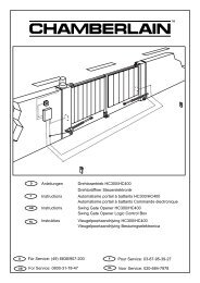
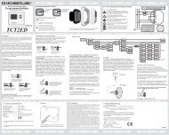
Typical configuration of a unit:1. Motor2. Control board3. photocell (active for closing), max. height 200 mmFirst photocell.4. photocell (active for opening), max. height 200 mmSecond photocell.5. Flashing light (optional)Important visual information on the movement of the gate.6. Key-operated switchIs mounted on the outside. The gate is opened by key or byentering a number.7. Contact strip (optional)Safeguards the gate on being touched. Contact strips can bemounted on the gate or on the pillars. If required, contact stripsmust be mounted at a height of up to 2.5m.8. photocell (active for opening/closing), max. height 200 mm(optional)en-3The control board complies with the latest EUguidelines. One of these guidelines specifies that the closingforces at the gate edge must not exceed 400 N (40 kg) for the last500 mm before the door is CLOSED. Above 500 mm, themaximum force at the gate edge must not exceed 1400 N (140kg). If this cannot be ensured, a contact strip must be mounted onthe gate at a height up to 2.5 m or on the pillar on the oppositeside (EN12453).MOTORS:The motor to open first is the “master “ motor 1, the other one isthe “second” motor 2. If only one motor is used, the connectionfor motor 2 is held in reserve.The cable for the capacitors supplied with the motors must beinserted in terminals OP and CL together with the cables for thedirection of rotation (brown/black). For space reasons thecapacitors may also be installed in the distribution boxes. Makesure that they are connected correctly and powered sufficiently.The capacitors are responsible for the force that the motors willhave later on.First connect the motors as follows:Motor 14 Brown & capacitor 15 Blue6 Black & capacitor 1—————————————————————Motor 27 Black & capacitor 28 Blue9 Brown & capacitor 2To start up see the section Initial operation / basic setting.Note: During initial operation, the gate wings must OPEN forthe first run. If one or both wings close(s) instead of opening,the brown and black cables must be swapped on this motor.Disconnect from the power supply before doing so!