cb11coverfreshDIYversion reworked.qxp - Nothnagel
cb11coverfreshDIYversion reworked.qxp - Nothnagel
cb11coverfreshDIYversion reworked.qxp - Nothnagel
- No tags were found...

Create successful ePaper yourself
Turn your PDF publications into a flip-book with our unique Google optimized e-Paper software.
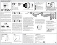
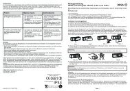
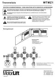
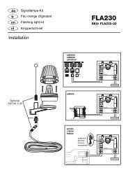
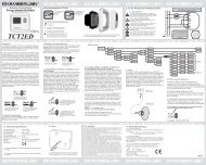
JUMPERSProgramming of failsafe photocells model 771EML1.Before the Initial Setup2.When connecting or removing photocell(s)- Switch off control board ( disconnect from current)- Slip jumper on designated pins- Dipswitch 5 to “ON”- Connect photocell(s) according illustration- Reconnect control board, wait short-time- Pull jumper, wait short-timeDone! (The number of photocells connected are stored)en-7Programming of relay photocells such as 263EMLThe control board must be disconnected from the mains for a fewseconds. All terminals to which no photocell is connected must bebridged with COM. (21-24, 22-24, 23-24). The power supply for therelay photocell of terminals 15-16. Dip switch 5 must be at OFF. Thejumper must be unplugged.Note: Relay photocells are no longer permitted for new installationsas per EN12978, because they cannot perform self-checks (failsafe).Operation without photocellsDANGER: Not permitted for normal operation. In this case contactstrips must safeguard the gate.The control board must be disconnected from the mains for a fewseconds. Terminals 21-22-23-24 must all be bridged. Dip switch 5must be at OFF. The jumper must be unplugged.Note: It is not possible to combine different photocell models.FLASHING LAMP (OPTIONAL)A flashing lamp can be connected to the control board. It warns whenthe gate is being moved. The flashing light should be fitted as high aspossible and in good clear view. The control board emits a constantsignal that the lamp converts to a flashing signal.Cable cross-section: 0.5 mm 2 or more.Voltage: 24 V DCDo not use any fixed copper lines. Do not lay any 230 voltcables in parallel and do not lay any 2 cables in the same cabletrunking.PUSHBUTTON / KEY-OPERATED SWITCH (OPTIONAL)The control board / drive can be activated using various inputs. Thiscan be done using a transmitter or keyswitch (terminals 17 and 20).Transmitter = see “Teaching the transmitter”Switch input 1 = input control 1 normal operationSwitch input 2 = input control 2 active for special settings(see Dip switch description)EMERGENCY STOP (OPTIONAL)A switch can be connected to stop or disable the unit. Themovement of the wings is stopped immediately. Terminals 19 and20 must be bridged if no switch is installed.34EML41EML24 VDC - OUTPUTFor relay infrared senors or other devices (e.g. receivers)max. 500 mADo not use any fixed copper lines. Do not lay any 230 voltcables in parallel and do not lay any 2 cables in the same cabletrunking.