cb11coverfreshDIYversion reworked.qxp - Nothnagel
cb11coverfreshDIYversion reworked.qxp - Nothnagel
cb11coverfreshDIYversion reworked.qxp - Nothnagel
- No tags were found...

You also want an ePaper? Increase the reach of your titles
YUMPU automatically turns print PDFs into web optimized ePapers that Google loves.
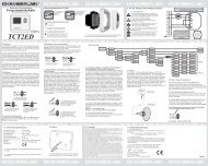
PROGRAMSThe control board has 3 operating modes (programs). The desiredprogram is set using the dip switch “ON” or “OFF”.en-5DIP1ONOFFDIP2ONOFFThe various operating modes are assigned to thedrives (see separate table)DIP3ONOFFno functionDIP4DIP5ONOFFSetting for Chamberlain photocells (771EML), complieswith EN60335-2-103.Setting for relay-controlled photocells (263EML) orother relay photocells.Preflash function of flashing light 2 seconds before thedrive starts.Preflash function disabledDIP6ONOFFDIP7DIP8ONOFFOnce the gate has fully opened, drive 1 moves thegate with maximum force for 1 second in “OPEN”direction.Function disabledno functionOnly modify settings when control bordis disconnected. Otherwise modifications willnot be accepted!!!POTENTIOMETERPT1 (TRIMMING POTENTIOMETER 1): BIPART DELAYControls the bipart delay if wings overlap. For OPEN = 0 or 3 sec. ForCLOSED = 0-20 sec. Motor 1 (master) is opened first and closed last.It is necessary that the bipart delay is always set so that nobody iscaught between the wings when they close. Left stop: Bipart delayOFFPT2 (TRIMMING POTENTIOMETER 2): AUTOMATIC CLOSING(TIMER TO CLOSE)The waiting time for the gate for GATE OPEN can be defined. Thegate is closed 0-150 sec. after the set time expires.Only working with failsafe photocell(s) 771EML installed.Left stop: Automatic closing OFFThe control board complies with the latest EU guidelines.One of these guidelines specifies that the closing forces at the gateedge must not exceed 400 N (40 kg) for the last 500 mm before thedoor is CLOSED. Above 500 mm, the maximum force at the gateedge must not exceed 1400 N (140 kg). If this cannot be ensured, acontact strip must be mounted on the gate at a height up to 2.5 m oron the opposite pillar (EN12453).PT3 (TRIMMING POTENTIOMETER 3): FORCE SETTING (FORCE1 MASTER)Definition of the force with which motor 1 = master is to operate. Therequired force depends on weight and function of the gate.Only modify settings when control bordis disconnected. Otherwise modifications willnot be accepted!!!PT4 (TRIMMING POTENTIOMETER 4): FORCE SETTING (FORCE2 SECOND)Definition of the force with which motor 2 = second is to operate. Therequired force depends on weight and function of the gate.