Descarga el catálogo 2007 (pdf) - Cydesa
Descarga el catálogo 2007 (pdf) - Cydesa
Descarga el catálogo 2007 (pdf) - Cydesa
- No tags were found...

You also want an ePaper? Increase the reach of your titles
YUMPU automatically turns print PDFs into web optimized ePapers that Google loves.
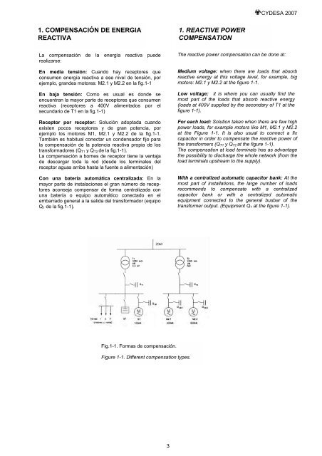
CYDESA <strong>2007</strong>1. COMPENSACIÓN DE ENERGIAREACTIVA1. REACTIVE POWERCOMPENSATIONLa compensación de la energía reactiva puederealizarse:En media tensión: Cuando hay receptores queconsumen energía reactiva a ese niv<strong>el</strong> de tensión, porejemplo, grandes motores: M2.1 y M2.2 en la fig.1-1En baja tensión: Como es usual es donde seencuentran la mayor parte de receptores que consumenreactiva (receptores a 400V alimentados por <strong>el</strong>secundario de T1 en la fig.1-1)Receptor por receptor: Solución adoptada cuandoexisten pocos receptores y de gran potencia, porejemplo los motores M1, M2.1 y M2.2 de la fig.1-1.También es habitual conectar un condensador fijo parala compensación de la potencia reactiva propia de lostransformadores (Q T1 y Q T2 de la fig.1-1).La compensación a bornes de receptor tiene la ventajade descargar toda la red (desde los terminales d<strong>el</strong>receptor aguas arriba hasta la fuente a alimentación)Con una batería automática centralizada: En lamayor parte de instalaciones <strong>el</strong> gran número de receptoresaconseja compensar de forma centralizada conuna batería o equipo automático conectado en <strong>el</strong>embarrado general a la salida d<strong>el</strong> transformador (equipoQ 1 de la fig.1-1).The reactive power compensation can be done at:Medium voltage: when there are loads that absorbreactive energy at this voltage lev<strong>el</strong>, for example, bigmotors: M2.1 y M2.2 at the figure 1-1.Low voltage: it is where you can usually find themost part of the loads that absorb reactive energy(loads at 400V supplied by the secondary of T1 at thefigure 1-1).For each load: Solution taken when there are few highpower loads, for example motors like M1, M2.1 y M2.2at the Figure 1-1. It is also usual to connect a fixcapacitor in order to compensate the reactive power ofthe transformers (Q T1 y Q T2 at the figure 1-1).The compensation at load terminals has as advantagethe possibility to discharge the whole network (from th<strong>el</strong>oad terminals upstream to the supply).With a centralized automatic capacitor bank: At themost part of installations, the large number of loadsrecommends to compensate with a centralizedcapacitor bank or with a centralized automaticequipment connected to the general busbar of thetransformer output. (Equipment Q 1 at the figure 1-1).Fig.1-1. Formas de compensación.Figure 1-1. Different compensation types.3