Descarga el catálogo 2007 (pdf) - Cydesa
Descarga el catálogo 2007 (pdf) - Cydesa
Descarga el catálogo 2007 (pdf) - Cydesa
- No tags were found...

You also want an ePaper? Increase the reach of your titles
YUMPU automatically turns print PDFs into web optimized ePapers that Google loves.
ÍNDICE CONTENTSCORRECCIÓN DEL FACTOR DE POTENCIA POWER FACTOR CORRECTIONCompensación de energía reactiva 3 Reactive power compensationCompensación de transformadores 4 Transformers compensationCompensación de motores 6 Motors compensationTarifas <strong>el</strong>éctricas 10 Electrical tariffsCondensadores de baja tensión 11 Low voltage capacitorsCondensadores cilíndricos 13 Cylindrical capacitorsCondensadores prismáticos 15 Prismatic capacitorsCondensadores con seccionador + fusibles 17 Capacitors with fuses + switch disconnectorCondensadores con interruptor automático 18 Capacitors with automatic circuit-breakerCondensadores con contactor + fusibles 19 Capacitors with contactor + fusesCondensadores con filtros de rechazo 20 Capacitors with detuned filter circuitsReguladores 21 P.F. ControllersEquipos para compensación automática deenergía reactiva 24 Automatic capacitors banksEquipos estándar a 400V 25 Standard automatic capacitors banks at400VEquipos con condensadores reforzados 30 Overrated automatic capacitors banksEquipos a 230V 33 Automatic capacitors banks at 230VProtección diferencial 35 Residual current protectionArmónicos 36 HarmonicsReactancias para filtros 40 Reactors for detuned filtersCondensadores para filtros 41 Capacitors for detuned filtersEquipos con filtros de rechazo 42 Automatic capacitors banks with detunedfilter circuitCondensadores de media tensión 45 Medium voltage capacitorEquipos para compensación de energíaM.V. automatic capacitors banks for powerreactiva en M.T 49 factor correctionContactores para maniobra de condensadores 53 Capacitor switching contactorsCOMPLEMENTOS ACCESSORIESTransformadores de corriente sumadores 54 Adding current transformersTransformadores de corriente de núcleoCurrent transformers with a split corepartido 54Resistencias de descarga rápida 54 Fast discharge resistorsTABLAS TABLESCompensación de transformadores 4 + 47 Transformer compensationCompensación de motores 6 + 47 Motors compensationCálculo de la potencia de condensadores 9 Calculation of the capacitor output (Q=Pxf)(Q=Pxf)Secciones de cables, calibre deinterruptores y fusibles para condensadores 55-56Cable, switch disconnector and fuses forcapacitorsMAPA 57 MAP
CALIDADCYDESA posee un Sistema de Gestión de lacalidad basado en la norma ISO 9001 así comocertificaciones de producto por laboratoriosacreditados, los cuales permiten a nuestrosclientes confiar en los productos y servicios deCYDESA.Los condensadores ESTA – PhMKP poseen <strong>el</strong>certificado de Underwriter’s Laboratories, Inc.(UL).QUALITYCYDESA has a Quality Management Systembased on the standard ISO 9001,as w<strong>el</strong>l asother certificates of our products granted byimportant laboratories, which allows ourcustomers to trust in CYDESA's products andservices.The ESTAprop® capacitors are certified by theUnderwriter's Laboratories, Inc. (UL).El certificado incluye un ensayo destructivo, quepermite comprobar la seguridad y eficacia d<strong>el</strong>desconectador de sobrepresión. Para <strong>el</strong>lo ULrealiza inspecciones periódicas en la planta d<strong>el</strong>fabricante, para garantizar la calidad permanented<strong>el</strong> producto. Las baterías disponen d<strong>el</strong> certificadode ensayo según EN 61921-2004 d<strong>el</strong> laboratorioLabein.This certificate consists of a destructive test thatproves the security and the efficiency of theoverpressure tear-off fuse. With this purpose, ULcarries out several inspections in themanufacturer's factory in order to guarantee apermanent product quality. The capacitor bankshave the test certificate in r<strong>el</strong>ation to EN 61921-2004 of the Labein laboratory.2
CYDESA <strong>2007</strong>1. COMPENSACIÓN DE ENERGIAREACTIVA1. REACTIVE POWERCOMPENSATIONLa compensación de la energía reactiva puederealizarse:En media tensión: Cuando hay receptores queconsumen energía reactiva a ese niv<strong>el</strong> de tensión, porejemplo, grandes motores: M2.1 y M2.2 en la fig.1-1En baja tensión: Como es usual es donde seencuentran la mayor parte de receptores que consumenreactiva (receptores a 400V alimentados por <strong>el</strong>secundario de T1 en la fig.1-1)Receptor por receptor: Solución adoptada cuandoexisten pocos receptores y de gran potencia, porejemplo los motores M1, M2.1 y M2.2 de la fig.1-1.También es habitual conectar un condensador fijo parala compensación de la potencia reactiva propia de lostransformadores (Q T1 y Q T2 de la fig.1-1).La compensación a bornes de receptor tiene la ventajade descargar toda la red (desde los terminales d<strong>el</strong>receptor aguas arriba hasta la fuente a alimentación)Con una batería automática centralizada: En lamayor parte de instalaciones <strong>el</strong> gran número de receptoresaconseja compensar de forma centralizada conuna batería o equipo automático conectado en <strong>el</strong>embarrado general a la salida d<strong>el</strong> transformador (equipoQ 1 de la fig.1-1).The reactive power compensation can be done at:Medium voltage: when there are loads that absorbreactive energy at this voltage lev<strong>el</strong>, for example, bigmotors: M2.1 y M2.2 at the figure 1-1.Low voltage: it is where you can usually find themost part of the loads that absorb reactive energy(loads at 400V supplied by the secondary of T1 at thefigure 1-1).For each load: Solution taken when there are few highpower loads, for example motors like M1, M2.1 y M2.2at the Figure 1-1. It is also usual to connect a fixcapacitor in order to compensate the reactive power ofthe transformers (Q T1 y Q T2 at the figure 1-1).The compensation at load terminals has as advantagethe possibility to discharge the whole network (from th<strong>el</strong>oad terminals upstream to the supply).With a centralized automatic capacitor bank: At themost part of installations, the large number of loadsrecommends to compensate with a centralizedcapacitor bank or with a centralized automaticequipment connected to the general busbar of thetransformer output. (Equipment Q 1 at the figure 1-1).Fig.1-1. Formas de compensación.Figure 1-1. Different compensation types.3
CYDESA <strong>2007</strong>1.1 COMPENSACIÓN DE TRANSFORMADORESTabla 1.1-I1.1 TRANSFORMER COMPENSATIONTable 1.1-IPotencia reactiva y de condensadores recomendadapara compensación de la reactiva propia detransformadores (se supone que <strong>el</strong> trafo está al 80%de su potencia nominal)Reactive power and recommended capacitors tocompensate the transformer reactive power (weassume that the transformer is being used at a rate of80% of its rated power).Serie hasta 24 kVSeries up to 24 kVSerie hasta 36 kVSeries up to 36 kVPotencia nominal (Sn)Rated power (Sn)Potencia reactiva apotencia nominalReactive output at arated powerPotencia de condensadoresrecomendada al 80% de lapotencia nominalRecommended capacitors outputat a rate of 80% of thetransformer rated powerPotencia reactiva apotencia nominalReactive output atrated powerPotencia de condensadoresrecomendada al 80% de lapotencia nominalRecommended capacitorsoutput at a rate of 80% of thetransformer rated powekVA kvar kvar kvar kvar25 2,0 2 2,3 250 3,7 3 3,9 3100 6,5 5 7,0 5160 10,1 7,5 10,4 7,5250 15,0 10 16,0 10400 23,2 15 24,8 20500 28,5 20 30,0 25630 35,3 25 36,5 25800 59,2 40 60,8 401000 73,0 50 75,0 501250 90,0 60 92,5 701600 113,6 80 116,8 802000 140,0 100 144,0 1002500 172,5 120 175,0 120En <strong>el</strong> supuesto de que <strong>el</strong> transformador esté trabajandohabitualmente con una potencia distinta o paratransformadores no normalizados, <strong>el</strong> cálculo de lapotencia d<strong>el</strong> condensador deberá efectuarse aplicandola expresión:On the assumption that the transformer usually workswith a different power or for not normalizedtransformers, the calculus of the capacitor output willhave to be carried out by applying the followingexpression:Q SNbi100oukГ b100 SSN2b SNQ SNbi100oukГ b100 SSN2b SNsiendo:S N, potencia nominal d<strong>el</strong> Trafo (kVA)i o, corriente de vacío en %U k, Tensión de cc.en %S, potencia real de trabajo en kVA.When:S N, transformer rated power (kVA)i o, unload current in %U k, impedance in %S, real service power in kVA.4
CYDESA <strong>2007</strong>EjemploTrafo de 630 kVA de potencia nominal con unai o=0,95%, U k=6% y trabajando al 50% de su potencianominal.630 b 0,95 6 2Q Г b 0.5 b 630 15,4kvar100 100Sin embargo, si este servicio no es permanente o <strong>el</strong>trafo puede ser cargado en un inmediato futuro hasta <strong>el</strong>80% o 100%, es preferible considerar la situaciónfutura, así aplicando la misma expresión para <strong>el</strong> 100%de su potencia nominal la potencia de condensadoresresultaría:630 b 0,95Q Г1006100b 630 38,4kvarConviene compensar <strong>el</strong> transformador con unescalón fijo reforzado.ExamplePower transformer of 630 kVA with i o=0, 95%, U k=6%,which works at a rate of 50% of its rated power.630 b 0,95 6 2Q Г b 0.5 b 630 15,4kvar100 100However, if this is not a continuous service or thetransformer can be loaded in a close future up to 80 or100%, it is better to consider the future situation,therefore, if the same expression is applied for the100% of its rated power, the capacitor power would be:630 b 0,95Q Г1006100b 630 38,4kvarTo compensate the transformer with a fix overratedstep is recommended.Fig.1.2-1. Compensación de untransformador y de los receptoresQ F, para <strong>el</strong> trafo y Q A, para losreceptoresFig. 1.2-1 Compensation of a transformer:Q F, for the transformer and Q A for the loads.Q F, escalón fijo para la compensación de la reactivapropia d<strong>el</strong> transformador, conectado antes d<strong>el</strong> TI quealimenta al regulador de la batería automática, (verversión SF en pág. 17). En los casos en que <strong>el</strong> cos φ aalcanzar sea inferior a la unidad puede conectarse <strong>el</strong>escalón fijo después d<strong>el</strong> TI siempre que <strong>el</strong>transformador no esté largos periodos de tiempo envacío o con carga muy baja (caso de serviciosestacionales o de campaña como riegos agrícolas,turísticos, ...)Q A, batería automática para compensar la carga d<strong>el</strong>transformador (receptores)Q F, fix step for the transformer reactive powercompensation, is connected before the CT for theautomatic capacitor bank controller, (See the SFversion on the page 17). When the cosφ to reach islower than the unit, the fix step can be connected afterthe CT, provided that the transformer doesn’t remainunload or with a very low load during long periods(that’s the case of seasonal services or of campaignssuch as agricultural irrigations, tourist installations …).Q A, automatic capacitor bank to compensate thetransformer loads.5
CYDESA <strong>2007</strong>1.2 COMPENSACIÓN DE MOTORESTabla 1.2-IPotencia reactiva de motores asíncronos juntoa la potencia de condensadores recomendada.1.2 MOTORS COMPENSATIONTable 1.2-IReactive power of induction motors togetherwith the recommended capacitors output.kW CVVacío/P.cargaUnload/Full LoadCond.Cap.Vacío/P.cargaUnload/Full LoadCond.Cap.Vacío/P.cargaUnload/Full LoadCondCap..Vacío/P.cargaUnload/Full LoadCond.Cap.Vacío/P.cargaUnload/Full LoadCond.Cap.kW HP kvar kvar kvar kvar kvar kvar kvar kvar kvar kvar3000 r.p.m. 1500 r.p.m. 1000 r.p.m. 750 r.p.m. 500 r.p.m.1,1 1,5 0,7/0,9 0,6 0,7/1,0 0,6 0,9/1,2 0,8 1,0/1,3 0,9 1,1/1,4 1,01,5 2 0,8/1,0 0,7 1,0/1,2 0,9 1,1/1,4 1,0 1,2/1,6 1,0 1,3/1,8 1,22,2 3 1,1/1,4 1,0 1,2/1,5 1,0 1,4/1,8 1,3 1,7/2,2 1,5 2,0/2,4 1,83 4 1,5/1,8 1,3 1,6/2,0 1,5 1,8/2,4 1,6 2,3/3,0 2,0 2,5/3,2 2,24 5,5 1,8/2,6 1,6 2,0/2,6 1,8 2,2/2,9 2,0 2,7/3,5 2,4 2,9/3,8 2,65,5 7,5 2,2/2,9 2,0 2,4/3,3 2,2 2,7/3,6 2,4 3,2/4,3 2,9 4,0/5,2 3,67,5 10 3,4/4,4 3,0 3,6/4,8 3,2 4,1/5,4 3,7 4,6/6,1 4,1 5,5/7,2 5,011 15 5,0/6,5 4,5 5,5/7,2 5,0 6,0/8,0 5,0 7,0/9,0 6,0 7,5/10 7,015 20 6,5/8,5 6,0 7,0/9,5 6,0 8,0/10 7,0 9,0/12 8,0 1,0/1,3 9,018,5 25 8,0/11 7,0 9,0/12 8,0 10/13 9,0 11/15 10 12/16 1022 30 10/12,5 9,0 11/13,5 10 12/15 10 13/16 12,5 16/18 1530 40 14/18 12,5 15/20 12,5 17/22 15 20/25 20 22/28 2037 50 18/24 15 20/27 20 22/30 20 26/34 25 29/39 2545 60 19/28 15 21/31 20 24/34 22 28/38 25 31/43 3055 75 22/34 20 25/37 20 28/41 25 32/46 30 36/52 3075 100 28/45 25 32/49 30 37/54 30 41/60 40 45/68 4090 125 34/54 30 39/59 35 44/65 40 48/72 45 54/83 50110 150 40/64 35 46/70 40 52/76 50 58/85 50 63/98 60132 180 45/72 40 53/80 50 60/87 50 67/97 60 75/110 70160 220 54/86 50 64/96 60 72/103 70 81/116 70 91/132 80200 270 66/103 60 77/115 70 87/125 80 97/140 80 110/160 100250 340 75/115 70 85/115 75 95/137 90 105/150 100 120/175 110Para potencias superiores considerar <strong>el</strong> 30% de la potenciaen kW d<strong>el</strong> motor Q [kvar] = 0,3·P [kW]For higher power consider the 30% of the power inKW of the motor Q [kvar] = 0,3·P [kW]La potencia de condensadores de la tabla 1.2-Icorresponde a la recomendación de EN 60831-1 deno superar <strong>el</strong> 90% de la potencia reactiva de vacíoThe capacitors power of the table 1.2.-Icorresponds to the recommendation of EN 60831-1of not overcoming the 90% of the unload reactivepower.Esta recomendación es necesaria para evitar laautoexcitación d<strong>el</strong> motor, fenómeno que se produce enmotores que puedan ser arrastrados por la carga aldesconectarlos de la red y siempre que <strong>el</strong> condensadorse conecte a bornes d<strong>el</strong> motor. Si no se dan estascircunstancias, <strong>el</strong> condensador puede llegar aigualar la potencia reactiva a plena carga d<strong>el</strong> motor.EjemploMotor que acciona una máquina de gran inercia (riesgode autoexcitación), potencia 75 kW a 1500 r.p.m. Setomará <strong>el</strong> valor indicado en la tabla: 30 kvar para lapotencia d<strong>el</strong> condensador.Si <strong>el</strong> condensador se conectara a bornes d<strong>el</strong> motor peroa través de un contactor no sería necesaria la limitacióncitada d<strong>el</strong> 90% de la reactiva de vacío. En este casopodría llegar a compensarse hasta 49 kvar según seindica en la tabla.This recommendation is required to avoid the motors<strong>el</strong>f-excitation, situation produced in motors that canrun down when they are disconnected of the network,provided that the capacitor is connected to the motorterminals. In other circumstances, the capacitor canachieve the reactive power produced by the motor atfull load.ExampleMotor that starts a large inertia machine (risk of s<strong>el</strong>fexcitation),power 75kW for 1500 r.p.m. The valuewritten on the table will be taken: 30 kvar for thecapacitor power.If the capacitor would be connected to the motorterminals but through a contactor, the aforementionedlimit of 90% of the unload reactive power would not benecessary. In that case, it could be compensated up to49 kvar as it is shown in the table.6
CYDESA <strong>2007</strong>EjemploMotor de 350 kW, para accionamiento de una bombacon cos φ 1 a plena carga de 0,88 y rendimiento d<strong>el</strong>97%, se desea compensar a cos φ 2=0,97.Se calcula la potencia d<strong>el</strong> condensador de la formahabitual por la fórmula tradicional (ver tabla 1.3-I)Q P b fEn este caso y según la mencionada tabla, f=0,289luego,Q 3500,97b 0,289 104kvarEn motores con arranque estr<strong>el</strong>la-triángulocompensar conectando <strong>el</strong> condensador al lado d<strong>el</strong>contactor de línea o con un contactorindependiente.ExampleMotor of 350 kW that drives a pump with cosφ 1 at fullload of 0,88 and efficiency of 97%, we wish tocompensate up to cosφ 2=0,97.The capacitor power is calculated as usual by thetraditional formula (see table 1.3-I).Q P b fIn that case and according to the table mentionedabove, f=0,289 then,Q 3500,97b 0,289 104kvarThe motors with a star-d<strong>el</strong>ta starting must becompensated connecting the capacitor to the linecontactorside or with an independent contactor.Fig 1.2-2 Compensación en caso de arranque estr<strong>el</strong>latriánguloEn motores con arrancadores estáticos, conectar <strong>el</strong>condensador antes d<strong>el</strong> arrancador, solución (a) o(b) de la figura 1.2-3Fig. 1.2-2 Compensation with a star-d<strong>el</strong>ta starting.For motors with static starters is recommended toconnect the capacitor before the starter, solution(a) or (b) of the figure 1.2-3Fig. 1.2-3. Compensación de arrencadores estáticosFig 1.2-3 Compensation of static startersPara compensación de otros receptores consultar <strong>el</strong>MANUAL CYDESA7
CYDESA <strong>2007</strong>1.3 COMPENSACIÓN CENTRALIZADA1.3 CENTRALIZED COMPENSATIONEs la forma más habitual de compensar instalacionesdonde como es usual hay numerosos receptores.It’s the most usual way to compensate installationswhere there are normally several loads.1.3.1 CÁLCULO DE LA POTENCIA DECONDENSADORES EN UNA INSTALA-CIÓN EN PROYECTO.1.3.1 CALCULUS OF THE CAPACITORSPOWER IN AN INSTALLATION INPROJECTD<strong>el</strong> proyecto puede extraerse:- Potencia total instalada .... P T (kW)- Factor de simultaniedad .... Fs (%)- Cos φ medio .... Cosφ 1Si se desea alcanzar un cos φ 2, la potencia necesariade condensadores será:From the project we can get the following information:- Total installed power .... P T (kW)- Simultaneity factor .... Fs (%)- The average cos φ .... cosφ 1If we want to achieve a cos φ 2, the required capacitorspower will be:Q PTFsb b100Fs100tan tan P b b f1 2TQ PTFsb b100Fs100tan tan P b b f1 2T(f = valor obtenido de la tabla 1.3-I)(f = value taken from the table 1.3-I)Ejemplo 1.3-1Instalación donde se conoce que la potencia d<strong>el</strong>conjunto de receptores es de 230 kW, de los que su<strong>el</strong>enfuncionar <strong>el</strong> 50%. Se estima un cosφ medio de 0,8 y sequiere alcanzar un cosφ de 0,98.Se determina f= 0,547 por la tabla 1.3-I por tanto,50Q 230 b b 0,547 63kvar100Ejemplo 1.3-2Se pretende compensar una instalación alimentada porun trafo de 1000 kVA desconociendo con exactitud lapotencia instalada así como <strong>el</strong> cosφ y <strong>el</strong> factor desimultaneidad.Se pueden estimar como valores habituales:Cosφ 1= 0,8Cosφ 2= 0,95Trafo: u =6% y 80% de P.C.kLa potencia de condensadores sería:Q F (para <strong>el</strong> trafo)= 50kvar (tabla 1.1-I)Q (para receptores)= 1000x0,8x0,8x(tanφ 1– tanφ 2)=1000x0,64x0,421=269kvarExample 1.3-1Installation where it is known that the set of loadspower is of 230 kW, and only the half of them are onservice. An average cosφ of 0,8 is considered and wewant to reach a cosφ of 0,98. We fix the value f= 0,547from the table 1.3-I, therefore,50Q 230 b b 0,547 63kvar100Example 1.3-2We try to compensate an installation fed by a trafo of1000 kVA when the installed power as w<strong>el</strong>l as the cosand the simultaneity factor are not exactly known.As usual values we can consider:Cosφ 1= 0,8Cosφ 2= 0,95Transformer:uk=6% and 80% of full load.The capacitor output will be:Q F (for the transformer)= 50kvar (table 1.1-I)Q (for load)= 1000x0,8x0,8x(tanφ 1– tanφ 2)=1000x0,64x0,421=269kvar8
CYDESA <strong>2007</strong>TABLA 1.3-I - FACTOR f = tanφ 1 -tanφ 2TABLE 1.3-I -f FACTOR = tanφ 1 -tanφ 2Q[kvar] Potencia de Condensadores = P[kW] potencia activa x fQ[kvar] Capacitors Output = P[kW] active power x fExistenteGivenFactor de potencia deseado (cosφ 2)Target power factor (cosφ 2)Tan φ 1 Cos φ 1 0,80 0,85 0,90 0,91 0,92 0,93 0,94 0,95 0,96 0,97 0,98 0,99 1,001,98 0,45 1,235 1,365 1,500 1,529 1,159 1,589 1,622 1,656 1,693 1,734 1,781 1,842 1,9851,93 0,46 1,180 1,311 1,446 1,475 1,504 1,535 1,567 1,602 1,639 1,680 1,727 1,788 1,9301,88 0,47 1,128 1,258 1,394 1,422 1,452 1,483 1,515 1,549 1,586 1,627 1,675 1,736 1,8781,83 0,48 1,078 1,208 1,343 1,372 1,402 1,432 1,465 1,499 1,536 1,577 1,625 1,685 1,8281,78 0,49 1,029 1,159 1,295 1,323 1,353 1,384 1,416 1,450 1,487 1,528 1,576 1,637 1,7791,73 0,50 0,982 1,112 1,248 1,276 1,306 1,337 1,369 1,403 1,440 1,481 1,529 1,590 1,7321,69 0,51 0,937 1,067 1,202 1,231 1,261 1,291 1,324 1,358 1,395 1,436 1,484 1,544 1,6871,64 0,52 0,893 1,023 1,158 1,187 1,217 1,247 1,280 1,314 1,351 1,392 1,440 1,500 1,6431,60 0,53 0,850 0,980 1,116 1,144 1,174 1,205 1,237 1,271 1,308 1,349 1,397 1,458 1,6001,56 0,54 0,809 0,939 1,074 1,103 1,133 1,163 1,196 1,230 1,267 1,308 1,356 1,416 1,5591,52 0,55 0,768 0,899 1,034 1,063 1,092 1,123 1,156 1,190 1,227 1,268 1,315 1,376 1,5181,48 0,56 0,729 0,860 0,995 1,024 1,053 1,084 1,116 1,151 1,188 1,229 1,276 1,337 1,4791,44 0,57 0,691 0,822 0,957 0,986 1,015 1,046 1,079 1,113 1,150 1,191 1,238 1,299 1,4411,40 0,58 0,655 0,785 0,920 0,949 0,979 1,009 1,042 1,076 1,113 1,154 1,201 1,262 1,4051,37 0,59 0,618 0,749 0,884 0,913 0,942 0,973 1,006 1,040 1,077 1,118 1,165 1,226 1,3681,33 0,60 0,583 0,714 0,849 0,878 0,907 0,938 0,970 1,005 1,042 1,083 1,130 1,191 1,3331,30 0,61 0,549 0,679 0,815 0,843 0,873 0,904 0,936 0,970 1,007 1,048 1,096 1,157 1,2991,27 0,62 0,515 0,646 0,781 0,810 0,839 0,870 0,903 0,937 0,974 1,015 1,062 1,123 1,2651,23 0,63 0,483 0,613 0,748 0,777 0,807 0,837 0,870 0,904 0,941 0,982 1,030 1,090 1,2331,20 0,64 0,451 0,581 0,716 0,745 0,775 0,805 0,838 0,872 0,909 0,950 0,998 1,058 1,2011,17 0,65 0,419 0,549 0,685 0,714 0,743 0,774 0,806 0,840 0,877 0,919 0,966 1,027 1,1691,14 0,66 0,388 0,519 0,654 0,683 0,712 0,743 0,775 0,810 0,847 0,888 0,935 0,996 1,1381,11 0,67 0,358 0,488 0,624 0,652 0,682 0,713 0,745 0,779 0,816 0,857 0,905 0,966 1,1081,08 0,68 0,328 0,459 0,594 0,623 0,652 0,683 0,715 0,750 0,787 0,828 0,875 0,936 1,0781,05 0,69 0,299 0,429 0,565 0,593 0,623 0,654 0,686 0,720 0,757 0,798 0,846 0,907 1,0491,02 0,70 0,270 0,400 0,536 0,565 0,594 0,625 0,657 0,692 0,729 0,770 0,817 0,878 1,0200,99 0,71 0,242 0,372 0,508 0,536 0,566 0,597 0,629 0,663 0,700 0,741 0,789 0,849 0,9920,96 0,72 0,214 0,344 0,480 0,508 0,538 0,569 0,601 0,635 0,672 0,713 0,761 0,821 0,9640,94 0,73 0,186 0,316 0,452 0,481 0,510 0,541 0,573 0,608 0,645 0,686 0,733 0,794 0,9360,91 0,74 0,159 0,289 0,425 0,453 0,483 0,514 0,546 0,580 0,617 0,658 0,706 0,766 0,9090,88 0,75 0,132 0,262 0,398 0,426 0,456 0,487 0,519 0,553 0,590 0,631 0,679 0,739 0,8820,86 0,76 0,105 0,235 0,371 0,400 0,429 0,460 0,492 0,526 0,563 0,605 0,652 0,713 0,8550,83 0,77 0,079 0,209 0,344 0,373 0,403 0,433 0,466 0,500 0,537 0,578 0,626 0,686 0,8290,80 0,78 0,052 0,183 0,318 0,347 0,376 0,407 0,439 0,474 0,511 0,552 0,599 0,660 0,8020,78 0,79 0,026 0,156 0,292 0,320 0,350 0,381 0,413 0,447 0,484 0,525 0,573 0,634 0,7760,75 0,80 0,130 0,266 0,294 0,324 0,355 0,387 0,421 0,458 0,499 0,547 0,608 0,7500,72 0,81 0,104 0,240 0,268 0,298 0,329 0,361 0,395 0,432 0,473 0,521 0,581 0,7240,70 0,82 0,078 0,214 0,242 0,272 0,303 0,335 0,369 0,406 0,447 0,495 0,556 0,6980,67 0,83 0,052 0,188 0,216 0,246 0,277 0,309 0,343 0,380 0,421 0,469 0,530 0,6720,65 0,84 0,026 0,162 0,190 0,220 0,251 0,283 0,317 0,354 0,395 0,443 0,503 0,6460,62 0,85 0,000 0,135 0,164 0,194 0,225 0,257 0,291 0,328 0,369 0,417 0,477 0,6200,59 0,86 0,109 0,138 0,167 0,198 0,230 0,265 0,302 0,343 0,390 0,451 0,5930,57 0,87 0,082 0,111 0,141 0,172 0,204 0,238 0,275 0,316 0,364 0,424 0,5670,54 0,88 0,055 0,084 0,114 0,145 0,177 0,211 0,248 0,289 0,337 0,397 0,5400,51 0,89 0,028 0,057 0,086 0,117 0,149 0,184 0,221 0,262 0,309 0,370 0,5120,48 0,90 0,029 0,058 0,089 0,121 0,156 0,193 0,234 0,281 0,342 0,4840,46 0,91 0,030 0,060 0,093 0,127 0,164 0,205 0,253 0,313 0,4560,43 0,92 0,031 0,063 0,097 0,134 0,175 0,223 0,284 0,4260,40 0,93 0,032 0,067 0,104 0,145 0,192 0,253 0,3950,36 0,94 0,034 0,071 0,112 0,160 0,220 0,363Q kvar( P kW( b f0,33 0,95 0,037 0,078 0,126 0,186 0,3290,29 0,96 0,041 0,089 0,149 0,2920,25 0,970,048 0,108 0,2510,20 0,98 0,061 0,2030,14 0,99 0,142Tabla 1.3-I. Determinación d<strong>el</strong> factor f para <strong>el</strong> cálculo de la potencia necesaria de condensadores Q. Para <strong>el</strong> cálculo, se halla primero tan φ 1=Q(reactiva)/P (activa). Con este dato la tabla proporciona <strong>el</strong> cos φ 1 existente correspondiente. Una vez <strong>el</strong>egido <strong>el</strong> cos φ 2 que se desea, puededeterminarse <strong>el</strong> factor f y con <strong>el</strong>lo la potencia necesaria de condensadores Q=P.f.Table 1.3-I. Determination of f factor for the calculation of the required power of capacitors Q. In order to find this value, we have to find, first ofall, the tan φ 1=Q (reactive)/P (active).With this information, the table gives us the corresponding cosφ 1. Once the desired cosφ 2 has beenchosen, we can determine the f factor and with it the required power of the capacitors Q=P.f9
CYDESA <strong>2007</strong>1.4 TARIFAS ELÉCTRICASLas tarifas <strong>el</strong>éctricas generalmente contemplanincentivos para reducir <strong>el</strong> consumo de energía reactivaespecialmente en periodos de máximo consumo,contribuyendo de esta forma a regular la tensión de lared y a reducir sus pérdidas.La forma de penalizar su consumo consistecomúnmente en facturar <strong>el</strong> exceso de reactivaconsumida, es decir, aqu<strong>el</strong> consumo que supere unporcentaje determinado d<strong>el</strong> consumo de energía activa.Dependiendo d<strong>el</strong> país este porcentaje varía entre <strong>el</strong> 33y 50%, lo que implica un cosφ comprendido entre 0,95 y0,90 aproximadamente.1.4 ELECTRICAL TARIFFSThe <strong>el</strong>ectric tariffs usually consider incentives in orderto reduce the reactive energy consumption, especiallyduring the high-load periods, h<strong>el</strong>ping by this way tocontrol the network voltage and to reduce its losses.The way to punish this consumption is usually basedon invoicing the reactive overconsumption, that is, thereactive consumption that overcomes a certainpercentage of the active energy consumption.This percentage is different in each country and itranges from 33% to 50%, which means having a cosφapproximat<strong>el</strong>y between 0, 95 and 0, 90.1.4.1 TARIFAS ELÉCTRICAS EN ESPAÑAConviven las tarifas propiamente dichas junto a las correspondientes d<strong>el</strong> mercado liberalizado (clientes cualificados)con notables diferencias entre ambas. En la tabla siguiente se resumen ambas formas de penalizar la energía reactivasegún <strong>el</strong> tipo de cliente. Para realizar estudios tanto de ahorro como de cálculo de condensadores solicitar nuestrosoftware CYDESA PFC.La energía reactiva en las tarifas <strong>el</strong>éctricas de <strong>2007</strong> (R.D. 1634/2006)Cliente No cualificadoCliente cualificadoTarifa 1.0 2.0 Resto Tarifa 2.0A 3.0A y 3.1A 6.1 a 6.5Periodos con recargo - - todos Periodo - 1 (punta) 2 (llano) 3 (valle) 1 a 5 6Recargo 0 (1) 0 (1) Kr (%) Cargo 0 T R T R 0 T R 0Cosφ Kr (%)>0,95…≤1≥0,9…≤0,95 0(37,026/cos 2 φ)-41,026
CYDESA <strong>2007</strong>2. CONDENSADORES DE BAJATENSIÓN2.1 Características2. LOW VOLTAGE CAPACITORS2.1 Technical dataNormas EN 60831-1 y 2 Standards EN 60831-1 and 2Di<strong>el</strong>éctrico Film de polipropileno metalizado Di<strong>el</strong>ectric Metallized polypropylene filmImpregnante “no PCB” Impregnant non - PCBTensionesNominales 230 V, 400 V, 440 V, 525 V, 690V y 1050V, 50 y 60 Hz.Rated voltages230 V, 400 V, 440 V, 525 V, 690 Vand 1050V, 50 and 60 Hz.Ejecuciones Tubular IP00 hasta 25 kvar /400V (30 kvar/440 V)Tubular IP54 hasta 25 kvar /400VTypesCylindrical IP00 up to 25 kvar /400 V(30 kvar/440 V)Cylindrical IP54 up to 25 kvar / 400VPrismática IP43 hasta 100 kvar /400 V Prismatic IP43 up to 100 kvar / 400 VPérdidas< 0,25 W / kvar para laejecución tubular< 0,5 W / kvar para ejecuciónprismática incluyendo laspérdidas en los cablesLosses< 0,25 W / kvar with the cylindricaltype< 0,5 W / kvar with the prismatic typeincluding cable losses.Tolerancia decapacidad±5% medida a 20ºC detemperatura ambienteTolerance oncapacitance±5% measured at 20ºC of ambienttemperatureSobretensiones(U N=tensión nominalde condensador)U N + 10% (hasta 8h al día)U N + 15% (hasta 30 min. al día)U N + 20% (hasta 5 min.)U N + 30% (hasta 1 min.)Overvoltages(U N=capacitor ratedvoltage)U N + 10% (up to 8h per day)U N + 15% (up to 30 min. per day)U N + 20% (up to 5 min.)U N + 30% (up to 1 min.)Sobrecarga decorriente(I N= Corrientenominal d<strong>el</strong>condensador) I N + 30%Current overload(I N= capacitor ratedcurrent) I N + 30%Ensayo de tensiónVoltage testEntre terminales 2,15 U N (AC), 2 segundos between terminals 2,15 U N (AC), 2 secondsEntre terminal ycaja4800 VAC, 2 segundosbetween terminaland casing4800 VAC, 2 secondsTemperaturaambienteAmbienttemperatureTubular IP00Tubular IP54 yPrismática-25 / D (máx. 55º C, media 24h45ºC)-25 / C (máx. 50º C, media 24h40ºC)Cylindrical IP00Cylindrical IP54and Prismatic-25 / D (max. 55º C, average 24h45ºC)-25 / C (max. 50º C, average 24h40ºC)11
CYDESA <strong>2007</strong>2.1 Características (continuación) 2.1 Technical data (from the previouspage)Condiciones deinstalaciónInstallationconditionsHumedad máx. 95% Humidity Max. 95%Altitud máx. 2000m. Altitude Max. 2000m.Ventilación natural Cooling NaturalPosición vertical (preferentemente) Position vertical (preferably)Esperanza de vida > 150.000 horas de servicio Life expectancy > 150.000 operating hoursCorriente deconexiónHasta 300 x I N (se recomiendareducir a ≤100 x I N mediante <strong>el</strong>empleo de contactores conresistencias previas)ConnectioncurrentUp to 300 x I N (it is recommended toreduce to ≤100 x I N with theapplication of contactors with previousresistors)Protección<strong>el</strong>éctricaDesconectador de sobrepresiónElectricalprotecionOverpressure tear-off fuseProtecciónmecánicaMechanicalprotectionTubularIP00, IP20 ( con cubrebornes ) ó Cylindrical IP00, IP20 ( with terminal cover ) orIP54IP54Prismática IP43 Prismatic IP43Fig. 2.1-1 Dispositivo de protección por sobrepresióninterna (desconectador de sobrepresión)Al producirse un defecto o perforación interna segeneran gases que presionando sobre la tapaprovocan la rotura de las conexiones.NOTA: debe dejarse un espacio libre de 25 mmcomo mínimo por encima de los terminales.Fig. 2.1-1 Protective device for internaloverpressure. (overpressure tear-off fuse)As soon as an internal breakdown occurs, gases arecreated. These gases press the cover and cause thetear-off of the internal fuses.NOTE: a free space of at least 25 mm over theterminals should be left.12
CYDESA <strong>2007</strong>2.2 Condensadores cilíndricos- Características pág. 11- Resistencias de descarga para 50 V, 1 min(IP00) ó 75 V, 3 min (IP54)2.2 Cylindrical capacitors- Technical data on page 11- Discharge resistor for 50 V, 1 min (IP00) or 75 V,3 min (IP54)POTENCIAOUTPUT230V, 50HzConexión por terminal faston o brida. Protección IP00 ó IP20 con cubrebornas (resistencias de descarga su<strong>el</strong>tas) (1)Fast-on or clamp terminal connection. Protection IP00 or IP20 with terminal cover (discharge resistors included) (1)2,5510kvarDIMENSIONESDIMENSIONS(mm)(W x H)64 x 19064 x 26584 x 265PESOWEIGHT0,81,11,9PhMKP 230/2,5/00 (2)230/5 /00 (2)230/10 /00 (3)CAP 64CAP 64CAP 84Con cable de conexión de 500 mm de longitud. Protección IP54 (resistencias de descarga incorporadas) (1)With connection cable of 500 mm. in length. Protection IP54 (discharge resistors assembled ) (1)2,551066 x 22566 x 30086 x 3000,91,22,0PhMKP 230/2,5/54230/5 /54230/10 /54(1) <strong>Descarga</strong> a 50 V en 1 min., excepto en protecciónIP54 (75 V, 3 min.)(2) Conexión por terminal faston(3) Conexión por terminal tipo brida.kgTIPOTYPECUBREBORNESTERMINALCOVERProtection IP 20400V, 50HzConexión por terminal faston. Protección IP00 ó IP20 con cubrebornes (resistencias de descarga su<strong>el</strong>tas) (1)Fast-on terminal connection. Protection IP00 or IP20 with terminal cover (discharge resistors included) (1)2,564 x 190 0,8 PhMKP 400/2,5 /00CAP 64564 x 190 0,8400/5 /00CAP 647,51012,564 x 19064 x 26564 x 2650,81,11,1400/7,5 /00400/10 /00400/12,5/00CAP 64CAP 64CAP 64Conexión por brida. Protección IP00 ó IP20 con cubrebornes (resistencias de descarga incorporadas) (1)Clamp connection. Protection IP00 or IP20 with terminal cover (discharge resistors assembled) (1)15202584 x 19084 x 26584 x 2651,41,91,9PhMKP 400/15/00400/20/00400/25/00CAP 84CAP 84CAP 84Con cable de conexión de 500 mm. de longitud. Protección IP54 (resistencias de descarga incorporadas) (1)With connection cable of 500 mm. in length. Protection IP54 (discharge resistors assembled) (1)2,557,51012,515202566 x 22566 x 22566 x 22566 x 30066 x 30086 x 22586 x 30086 x 3000,90,90,91,21,21,52,02,0PhMKPPhMKP400/2,5 /54400/5 /54400/7,5 /54400/10 /54400/12,5/54400/15 /54400/20 /54400/25 /54(1) Discharge at 50 V in 1 min., except with protection IP54(75 V, 3 min.)(2) Fast-on terminal connection(3) Clamp terminal connection.IP00IP20 (*)IP00IP20 (*)13IP54
CYDESA <strong>2007</strong>2.2 Condensadores cilíndricos (continuación) 2.2 Cylindrical capacitors (from previouspage)POTENCIAOUTPUTkvarDIMENSIONESDIMENSIONS(mm)(W x H)PESOWEIGHTkgTIPOTYPE440V, 50Hz525V, 50HzCUBREBORNESTERMINALCOVERProtection P20Conexión por terminal faston o brida. Protección IP00 ó IP20 con tapa de protección (resistencias de descargassu<strong>el</strong>tas) (1)Fast-on or clamp terminal connection. Protection IP00 or IP20 with protective cover (discharge resistors included ) (1)5101516,92022,52528,130Conexión por terminal faston o brida. Protección IP00 ó IP20 con tapa de protección (resistencias de descargassu<strong>el</strong>tas) (1)Fast-on or clamp terminal connection. Protection IP00 or IP20 with protective cover (discharge resistors included) (1)1015202564 x 19064 x 26584 x 19084 x 19084 x 26584 x 26584 x 26584 x 26584 x 34064 x 26584 x 19084 x 26584 x 2650,81,11,41,91,91,91,91,92,31,41,41,91,9PhMKP 440/5 /00 (2)440/10 /00 (2)440/15 /00 (3)440/16,9/00 (3)440/20 /00 (3)440/22,5/00 (3)440/25 /00 (3)440/28,1/00 (3)440/30 /00 (3)PhMKP 525/10 /00 (2)525/15 /00 (3)525/20 /00 (3)525/25 /00 (3)25 84 x 340(1) <strong>Descarga</strong> a 50 V en 1 min., excepto en protección IP54(75 V, 3 min.)(2) Conexión por terminal tipo faston,(3) Conexión por terminal tipo brida.690V, 50HzCAP 64CAP 64CAP 84CAP 84CAP 84CAP 84CAP 84CAP 84CAP 84Con cable de conexión de 500 mm. de longitud. Protección IP54 (resistencias de descarga incorporadas) (3)With connection cable of 500 mm. in length. Protection IP54 (discharge resistors assembled ) (3)566 x 225 0,9 PhMKP 440/5 /541015202566 x 30086 x 22586 x 30086 x 3001,21,52,02,0440/10 /54440/15 /54440/20 /54440/25 /54CAP 64CAP 84CAP 84CAP 84Conexión por terminal faston o brida. Protección IP00 ó IP20 con tapa de protección (resistencias de descargas su<strong>el</strong>tas) (1)Fast-on or clamp terminal connection. Protection IP00 or IP20 with protective cover (discharge resistors included) (1)10152064 x 26584 x 26584 x 340PhMKP 690/10 /00 (2)690/15 /00 (3)690/20 /00 (3)1,11,92,42,9690/25 /00 (3)CAP 64CAP 84CAP 84CAP 84(1) Discharge at 50 V in 1 min., except with protection IP54(75 V, 3 min.)(2) Fast-on terminal connection(3) Clamp terminal connection.IP00IP20 (*)IP00IP20 (*)IP5414
CYDESA <strong>2007</strong>2.3 Condensadores prismáticos- Características pág. 11- Resistencias de descarga incorporadas (75 V en3 min)- Protección IP43- Acabado RAL 70322 series: estandar y reforzadaLa serie estándar soporta 400V de forma permanente yuna sobretensión temporal hasta 440V como máximo8h/día.La serie reforzada soporta 440V de forma permanente yhasta 480V durante 8h/día. La potencia siempre estáreferida a 400V2.3 Prismatic capacitors- Technical data on page 11- Discharge resistors assembled (75 V in3 min)- Protection IP43- Painting colour RAL 70322 series: standard and overratedThe standard series can operate permanently at 400Vand temporary up to 480V maximum 8h/day.The overrated series can operate permanently at 440Vand temporary up to 480V maximum 8h/day. The power isalways referred to 400V.POTENCIAOUTPUTDIMENSIONESDIMENSIONSSERIE ESTANDARSTANDARD SERIESPESO TIPOWEIGHT TYPESERIE REFORZADAOVERRATED SERIESPOTENCIA TIPOOUTPUT TYPEkvar H x (A/A1) x B mm kg kvar400V, 50Hz10 430x(183/224)x98 5 PhP 400/1015 520x(195/236)x135 6 400/1520 6,5 400/2025 6,5 400/25 20 PhP 400R/2030 8 400/30 25 400R/2535 520x(260/300)x135 9 400/35 30 400R/3040 9 400/40 35 400R/3550 10 400/50 40 400R/4060 11 400/60 50 400R/5070 520x(395/435)x135 13 400/70 60 400R/6075 14 400/75 70 400R/7080 15 400/80 75 400R/75100 17 400/100 80 400R/80230V, 50Hz10 520x(195/236)x135 6,5 PhP 230/1015 7 230/1520 9 230/2025 520x(260/300)x135 10 230/2530 11 230/3035 520x(395/435)x135 13 230/3540 15 230/40440V, 50Hz10 430x(183/224)x98 5 PhP 440/1015 520x(195/236)x135 6 440/1520 6,5 440/2025 6,5 440/2530 8 440/3040 520x(260/300)x135 9 440/4050 10 440/5060 11 440/6070 13 440/7075 14 440/7580 520x(395/435)x135 15 440/80100 17 440/100(1)Terminales L1, L2 y L3(1)Terminals L1, L2 and L3M8 hasta/up to 400/20400R/20230/10440/20M10 hasta/up to 400/30400R/30230/15440/30M12 hasta/up to 400/100400R/80230/4015440/100(2)Terminal de tierra(2) Earthing terminalM6 hasta/up to 400/10400R/10440/10M10 hasta/up to 400/100400R/80230/40440/100
CYDESA <strong>2007</strong>2.3 Condensadores prismáticos(continuación)- Características pág. 11- Resistencias de descarga incorporadas (75 V en3 min)- Protección IP43- Acabado RAL 70322.3 Prismatic capacitors (from previouspage)- Technical data on page 11.- Discharge resistors included (75 V in 3 min)- Protection IP43- Painting colour RAL 7032POTENCIAOUTPUTDIMENSIONESDIMENSIONSPESOWEIGHTTIPOTYPEkvar H x (A/A1) x B mm kg525V, 50Hz10 430x(183/224)98 5 PhP 525/1020 520x(195/236)x135 6,5 525/2025 8 525/2530 9 525/3040 520x(260/300)x135 10 525/4050 11 525/5060 13 525/6075 520x(395/435)x135 15 525/75100 17 525/100690V, 50Hz20 520x(195/236)x135 7 PhP 690/2025 8 690/2530 9 690/3040 520x(260/300)x135 10 690/4050 11 690/5060 12 690/6075 520x(395/435)x135 15 690/75100 17 690/1001050V, 50Hz30 520x(260/300)x135 10 PhP 1050/3050 11 1050/5060 520x(395/435)x135 12 1050/6080 15 1050/80100 17 1050/100(1)Terminales L1, L2 y L3(1)Terminals L1, L2 and L3M8 hasta/up to 525/25690/25M10 hasta/up to 525/30690/30M12 hasta/up to 525/100690/1001050/100(2)Terminal de tierra(2) ) Earthing terminalM10 hasta/up to 525/100690/1001050/10016
CYDESA <strong>2007</strong>2.4 Condensadores con seccionador +fusibles2.4 Prismatic Capacitors with fuses andswitch disconnectorLos condensadores PhP.../SF incorporan un seccionadorcon fusibles con capacidad de corte en carga. Resultan lasolución idónea para compensación de receptoresindividuales. Se recomienda un accionamiento, conexión odesconexión, rápido pero sin esfuerzos excesivamentebruscos.Características generales: (pág. 11)N Protección IP40 (PhP), IP30 (EC)N Acabado RAL 7032Características d<strong>el</strong> seccionador:N Intensidad nominal 160 AN Fusible tipo NH00, I CC = 120 kAN Nº de maniobras > 2002 series: estandar y reforzadaLa serie estándar soporta 400V de forma permanente yuna sobretensión temporal hasta 440V como máximo8h/día.La serie reforzada soporta 440V de formapermanente y hasta 480V durante 8h/día. La potenciasiempre está referida a 400VSERIE ESTANDARSTANDARD SERIESPOTENCIA SECCIONADOR/ DIMENSIONES PESO TIPOOUTPUT FUSIBLES DIMENSIONS WEIGHT TYPEEJECUCIÓN PRISMÁTICA PhPPRISMATIC EQUIPMENT PhP(1)Terminales L1, L2 y L3(1)Terminals L1, L2 and L3M8 hasta /up to 400/20/SF400R/20/SFM10 hasta/ up to 400/30/SF400R/30/SFM12 hasta / up to 400/70/SF400R/70/SF(2)Terminal de tierra(2)Earthing terminalM6 hasta /up to 400/10/SF400R/10/SFM10 hasta /up to 400/70/SF400R/70/SFThe PhP.../SF capacitors have a fuse switch disconnectorwith load breaking capacity. They represent the perfectsolution to compensate single loads. A fast system ofdrive, connection or disconnection, without too abruptefforts is recommended.Technical data: (page 11)N Protection IP40 (PhP), IP30 (EC)N Painting colour RAL 7032Switch characteristics:N Rated current 160 AN Type fuse: NH00, I CC = 120 kAN Number of switching operations > 2002 series: standard and overratedThe standard series can operate permanently at 400Vand temporary up to 440V maximum 8h/day.The overrated series can operate permanently at 440Vand temporary up to 480V maximum 8h/day. The power isalways referred to 400V.SERIE REFORZADAOVERRATED SERIESPOTENCIA TIPOOUTPUT TYPESWITCH/FUSES H x (A/A1) x Bkvar A mm kg kvarEJECUCIÓN PRISMÁTICA 400V, 50Hz PRISMATIC EQUIPMENT10 160/25 520 x (260/312) x 135 8 PhP 400/10/SF -15 160/40 8,5 400/15/SF -20 160/50 8,5 400/20/SF 20 PhP 400R/20/SF25 160/63 9 400/25/SF 25 400R/25/SF30 160/80 10 400/30/SF 30 400R/30/SF35 160/80 11 400/35/SF 35 400R/35/SF40 160/100 11 400/40/SF 40 400R/40/SF50 160/125 12 400/50/SF60 160/160 720 x (260/312) x 135 13 (12)* 400/60/SF 50 400R/50/SF70 160/160 15 (13)* 400/70/SF 60 400R/60/SF- (15)* 70 400R/70/SFEJECUCIÓN EN CAJA MURAL (**) 400V, 50Hz WALL-MOUNTED EQUIPMENT80 160/160 800x600x250 44 EC 400/80/SF 80 EC 400R/80/SF100 250/200 44 EC 400/100/SF 100 EC 400R/100/SF120 250/224 46 EC 400/120/SF 120 EC 400R/120/SFEJECUCIÓN PRISMÁTICA 230V, 50Hz PRISMATIC EQUIPMENT10 160/40 520 x (260/312) x 135 8,5 PhP 230/10/SF15 160/63 9 230/15/SF20 160/80 11 230/20/SF25 160/100 720 x (260/312) x 135 12 230/25/SF30 160/125 13 230/30/SF35 160/160 15 230/35/SFEJECUCIÓN EN CAJA EC /EQUIPMENT WITH EC CABINET(*) peso correspondiente a ejecución reforzada (**) accionamiento d<strong>el</strong> seccionador en <strong>el</strong> interior d<strong>el</strong> armario(*) weight corresponding to the overrated equipments (**) switch disconnector hand<strong>el</strong> inside the cabinet17
CYDESA <strong>2007</strong>2.5 Condensadores prismáticos coninterruptor automático2.5 Prismatic capacitors with automaticcircuit-breakerLos condensadores PhP.../IA incorporan un interruptorautomático de alto poder de ruptura. Resultan la soluciónidónea para compensación de receptores individuales.Características generales: (pág. 11)N Protección IP40 (PhP), IP30 (EC)Características d<strong>el</strong> interruptor:N Poder de corte, Icu=Ics- 160A: 25 kA- 250A: 35kAN R<strong>el</strong>é térmico regulable y magnético fijo2 series: estandar y reforzadaLa serie estándar soporta 400V de forma permanente yuna sobretensión temporal hasta 440V como máximo8h/día.La serie reforzada soporta 440V de forma permanente yhasta 480V durante 8h/día. La potencia siempre estáreferida a 400VThe PhP.../IA capacitors have an automatic circuit-breakerwith a high breaking capacity. They represent the perfectsolution to compensate single loads.Technical data: (page 11)N Protection IP40 (PhP), IP30 (EC)Circuit-breaker characteristics:N Breaking capacity, Icu=Ics- 160A: 25 kA- 250A: 35 kAN Thermal adjustable and fix magnetic r<strong>el</strong>ay.2 series: standard and overratedThe standard series can operate permanently at 400Vand temporary up to 440V maximum 8h/day.The overrated series can operate permanently at 440Vand temporary up to 480V maximum 8h/day. The power isalways referred to 400V.POTENCIAOUTPUTINTERRUPTOR/RELÉCIRCUIT-BREAKER/RELAYDIMENSIONESDIMENSIONSH x (A/A1) x BSERIE ESTANDARSTANDARD SERIESPESO TIPOWEIGHT TYPESERIE REFORZADAOVERRATED SERIESPOTENCIA TIPOOUTPUT TYPEkvar A mm kg kvarEJECUCIÓN PRISMÁTICA 400V, 50Hz PRISMATIC EQUIPMENT10 160/20 520 x (260/300) x 135 8 PhP 400/10/IA15 160/30 8,5 400/15/IA20 160/40 8,5 400/20/IA 20 400R/20/IA25 160/50 9 400/25/IA 25 400R/25/IA30 160/60 10 400/30/IA 30 400R/30/IA35 160/70 11 400/35/IA 35 400R/35/IA40 160/80 11 400/40/IA 40 400R/40/IA50 160/100 13 400/50/IA60 160/125 (100)* 720 x (260/300) x 135 13 400/60/IA 50 400R/50/IA70 160/140 (125)* 15 (13)* 400/70/IA 60 400R/60/IA75 160/150 (140)* 16 (15)* 400/75/IA 70 400R/70/IA75 400R/75/IAEJECUCIÓN EN CAJA MURAL 400V, 50Hz WALL-MOUNTED EQUIPMENT80 250/160 800x600x250 45 EC 400/80/IA 80 EC 400R/80/IA100 250/200 45 EC 400/100/IA 100 EC 400R/100/IA120 250/240 47 EC 400/120/IA 120 EC 400R/120/IAEJECUCIÓN PRISMÁTICA PhPPRIMATIC EQUIPMENT PhP(1)Terminales L1, L2 y L3(1)Terminals L1, L2 and L3M8 hasta/up to400/20/IA400R/20/IAM10 hasta/up to 400/30/IA400R/30/IAM12 hasta/up to 400/75/IA400R/75/IA(2) Terminal de tierra(2) Earthing terminalM6 hasta/up to 400/10/IA400R/10/IAM10 hasta/ up to 400/75/IA400R/75/IAEJECUCIÓN EN CAJA EC /EQUIPMENT WITH EC CABINET(*) valores correspondientes a ejecución reforzada(*) values corresponding to oversized equipments18
CYDESA <strong>2007</strong>2.6. Condensadores con contactor + fusibles 2.6. Capacitors with contactor + fusesLos condensadores con contactor + fusibles resultan unasolución sencilla y rápida para:N Ampliar equipos de corrección automáticaN Compensación de receptores individuales en losque no se recomienda una conexión directa abornes, por ejemplo motores (ver 1.2)Características generales (ver pág. 11)N Pérdidas inferiores a 1,2 W/kvarN Protección IP30N Acometida inferiorN Acabado RAL 7032The capacitors with contactor + fuses represent a fast andeasy solution to:N Extend automatic equipments for the power factorcorrectionN Compensate single loads, when a directconnection to the terminals is not recommended,for example, motors (see 1.2)Technical data (see page 11)N Losses lower than 1,2 W/kvarN Protection IP30N Supply entry from the b<strong>el</strong>owN Painting colour RAL 7032POTENCIAOUTPUTFUSIBLESFUSESDIMENSIONESDIMENSIONSH x A x BSERIE ESTANDARSTANDARD SERIESPESO TIPOWEIGHT TYPESERIE REFORZADAOVERRATED SERIESTIPOTYPEkvar (A) (mm) kg400V, 50Hz20 40 500x400x200 23 EC 400/20/CF EC 400R/20/CF25 63 23 EC 400/25/CF EC 400R/25/CF30 63 30 EC 400/30/CF EC 400R/30/CF35 80 700x500x250 31 EC 400/35/CF EC 400R/35/CF40 100 32 EC 400/40/CF EC 400R/40/CF50 125 34 EC 400/50/CF EC 400R/50/CF60 125 36 EC 400/60/CF EC 400R/60/CF70 63+100 800x600x250 37 EC 400/70/CF EC 400R/70/CF75 63+125 37 EC 400/75/CF EC 400R/75/CF80 100+100 48 EC 400/80/CF EC 400R/80/CF100 125+125 48 EC 400/100/CF EC 400R/100/CF120 125+125 50 EC 400/120/CF EC 400R/120/CF(*) A partir de 75kvar(*) From 75kvar19
CYDESA <strong>2007</strong>2.7 Condensadores con reactancias parafiltros de rechazo (fr=189Hz)2.7 Capacitors with reactors for detunedfilter circuits (fr=189Hz)Incorporan condensadores con reactancias conectadas enserie formando un filtro L-C sintonizado a 189Hz parafrecuencia de red de 50Hz, (cap. 5)Estos filtros están indicados para la compensación fija demotores o transformadores (reactiva propia d<strong>el</strong> trafo) eninstalaciones con presencia de armónicos. Evitan lasobrecarga de los condensadores y <strong>el</strong>iminan la posibilidadde resonancia en la red. Al mismo tiempo reducen lascorrientes y tensiones armónicas en la red en un 25%aproximadamente (cap. 5)Características:N Condensadores de 440V de tensión asignadaN Reactancia para formar un filtro de rechazo sintonizadoa fr=189HzN Opcionalmente puede incorporarse interruptor generalde entrada y fusible de APR.N Pérdidas: consultar 5.4N Protección IP30.N Instalación mural o sobre su<strong>el</strong>o (1)N Acometida inferiorN Protección térmica:EF400/12,5…25: la reactancia incorpora un contactotérmico NC para actuar sobre un dispositivo de corteexterior.EF400/50…100 equipados con ventilación forzada:incorporan <strong>el</strong> contacto térmico de la reactancia y untermostato para conectar <strong>el</strong> ventilador.They have capacitors with serial connected reactorsforming a L-C filter tuned to 189Hz for 50Hz mainsfrequency, (chapter 5).These filters are recommended for the fixed compensationof motors or transformers (transformer reactive power) ininstallations containing harmonics. They avoid thecapacitors overload and they <strong>el</strong>iminate the possibility ofresonance. At the same time, they reduce the harmoniccurrents and voltages in approximat<strong>el</strong>y 25%(chapter 5).Technical data:N Capacitors rated voltage of 440VN Reactor to form a detuned filter tuned to fr=189HzN A general input circuit-breaker and a H.R.C. fuse canbe alternativ<strong>el</strong>y included.N Losses: see 5.4N Protection IP30.N Wall or floor mounting (1)N Supply entry from the b<strong>el</strong>ow.N Thermal protection:EF400/12,5…25: the reactor has a thermal contact NC inorder to act on a breaking outer device.EF400/50…100 equipped with forced cooling: they havethe thermal contact and a thermostat to switch on the fan.POTENCIAOUTPUTDIMENSIONESDIMENSIONSH x A x BPESOWEIGHT400V, 50HzTIPOTYPE..../FFUSIBLEFUSESUPLEMENTO POR:EXTRA PRICE FOR:..../INT/FINT+FUSINT+FUSkvar (mm) kg(A)(A)12,5 600 x 500 x 250 43 EF 400/12,5 35 63/2525 700 x 500 x 250 53 EF 400/25 60 63/50CON VENTILACIÓN FORZADAWITH FORCED COOLING50 800 x 600 x 250 (1) 82 EF 400/50 125 160/12575 1000 x 600 x 400 (1) 95 EF 400/75 160 160/160100 1000 x 600 x 400 (1) 110 EF 400/100 250 250/200(1) A partir de 50kvar se suministran con pies de 150mm dealtura.(1) From 50kvar they are provided with feet of 150mm ofheight20
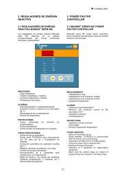
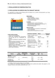
CYDESA <strong>2007</strong>3. REGULADORES DE ENERGÍAREACTIVA3. POWER FACTORCONTROLLER3.1 REGULADORES DE ENERGÍAREACTIVA MASING ® SERIE MCLos reguladores de energía reactiva Masing®serie MC disponen de un potentemicroprocesador que incluye numerosasfunciones y prestaciones:3.1 MASING ® SERIES MC POWERFACTOR CONTROLLERMasing® series MC power factor controllershave a powerful microprocessor that has severalfunctions and services:MEDICIONES- Cosφ instantáneo- Tensión instantánea y máxima- Corriente instantánea y máxima- Temperatura d<strong>el</strong> equipoALARMAS- Subcompensación y sobrecompensación- Corriente mínima y máxima en <strong>el</strong> secundariod<strong>el</strong> T.I.- Sobrecarga de los condensadores- Exceso de temperaturaPROTECCIONES- Contra sobrecarga de corriente encondensadores- Contra sobretensión- Contra exceso de temperatura en <strong>el</strong> equipoOTRAS PRESTACIONES- Opción de set up automático- Puerto serie TTL/RS232 para comunicacióncon PC para set up y visualización demedidas- Corrección automática de polaridad invertidad<strong>el</strong> T.I.- Medición d<strong>el</strong> factor de potencia y d<strong>el</strong> cosφ- Función de bloqueo d<strong>el</strong> teclado- Funcionamiento de 4 cuadrantes parainstalaciones con cogeneración- R<strong>el</strong>és de alarma y de mando d<strong>el</strong> ventiladormediante programación y utilizando los 2últimos r<strong>el</strong>és de escalones.MEASUREMENTS- Instantaneous cosφ- Instantaneous and maximum voltage- Instantaneous and maximum current- Equipment temperatureALARMS- Under and overcompensation- Minimum and maximum current on thesecondary of CT- Capacitors overload- OvertemperaturePROTECTIONS- Capacitors current overload- Overvoltage- Excess of equipment temperatureOTHER SERVICES- Option of automatic set up- Serial interface TTL/RS232 to communicatewith PC and for set up and testing.- Automatic correction of CT inverted polarity.- Cosφ and power factor measurement.- Keyboard locking information.- Operation of 4 quadrants for cogenerationequipment.- Alarm and fan control r<strong>el</strong>ays by means ofprogramming and using the 2 last step r<strong>el</strong>ays.21
CYDESA <strong>2007</strong>3.1 REGULADORES DE ENERGÍAREACTIVA MASING ® SERIE MC(continuación)3.1 MASING ® SERIES MC POWERFACTOR CONTROLLER (from theprevious page)Parámetros regulables Rango Ajuste pordefectoTensión nominal de loscondensadores 80-750V 400VCosφ de consigna 0,8 ind – 0,8 cap 1Retardo de conexión (1)Retardo de reconexión 5-240s 60sSensibilidad por escalón 5-600s 60sCorriente d<strong>el</strong> primario d<strong>el</strong>T.I. OFF-10.000 OFFPotencia d<strong>el</strong> escalón máspequeño 0,1-3000 25Coeficiente de paso 0-16 0Adjustable parameters Range Adjustmentby defaultCapacitors rated voltage 80-750V 400VTarget cosφ 0,8 ind – 0,8 cap 1Connection d<strong>el</strong>ay (1)Reconnection d<strong>el</strong>ay 5-240s 60sStep sensibility 5-600s 60sCurrent on the primary ofCT OFF-10.000 OFFPower of the smalleststep 0,1-3000 25Step coefficient 0-16 0MEDIDANº DEESCALONESDIMENSIONES(FRONTAL)XFONDOPROGRAMADE CONEXIÓNPESOTIPOMEASUREMENTNUMBER OFSTEPSDIMENSIONS(FRONT) X DEPTHCONNECTIONPROGRAMWEIGHTTYPEmmkgTensiónVoltage380-415VAC50/60HzConsumo 5-6VAConsumption 5-6VACorriente: 5ACurrent: 5AConsumo 0,6WConsumption 0,6W812(144x144)x701:1:1...1:1:2...1:2:2...1:2:3...(2)0,740,77MC8MC12(1) Variable en función d<strong>el</strong> valor <strong>el</strong>egido de lasensibilidad(2) Y cualquier otra combinación siempre que lar<strong>el</strong>ación entre la potencia d<strong>el</strong> escalón máspequeño y la de cualquier otro sea un valorentero comprendido entre 1 y 16(1) Variable depending on the sensibility chosenvalue.(2) And any other combination provided that ther<strong>el</strong>ation between the power of the smallest stepand another one is an integer value between 1and 16.22
CYDESA <strong>2007</strong>3.2 REGULADORES DE ENERGÍAREACTIVA SERIE RMLos reguladores RM destacan por su simplicidadsi bien dispone de un potente microprocesadorque permite realizar múltiples funciones:3.2 SERIES RM POWER FACTORCONTROLLERThe RM controllers highlight by their simplicity.However, they have a powerful microprocessorthat allows carrying out numerous functions:- Sistema FCP que minimiza <strong>el</strong> número demaniobras de los contactores.- Indicación de los pasos conectados- Indicación digital d<strong>el</strong> cosφ- Señalización d<strong>el</strong> signo de la potencia, L(inductiva), C (capacitiva)- Configuración de: cosφ de consigna,retardo de conexión, valor de la sensibilidadC/K y número de escalones- Posibilidad de empleo en 50Hz o 60Hz- FCP system that minimizes the number ofcontactors operations.- Indication of the connected steps.- Digital indication of the cosφ- Indication of the reactive power type, L(inductive), C (capacitive)- Configuration of: target cosφ, connectiond<strong>el</strong>ay, C/K sensibility value and number ofsteps.- Possible use in 50Hz or 60HzTENSIÓN DEMEDIDANº DEESCALONESDIMENSIONES(frontal)xfondoPROGRAMASDECONEXIÓNTIPOPESOMEASUREMENTVOLTAGEV400NUMBER OFSTEPSDIMENSIONS(front) x depthmmCONNECTIONPROGRAMTYPEWEIGHT-10% + 15% 6 (144x144)x62 1:1:1:1 RM6 0,4345-65Hz121:1:2:21:2:2:2 RM12 0,49ConsumoConsumption1:2:4:41:2:4:8Máx. 5,5VA (RM6)8,5 VA (RM12)Parámetros regulables Rango Ajuste pordefectoAdjustable parameters Range Adjustmentby defaultCosφ de consigna 0,85 ind a 1,00 Target cosφ 0,85 ind up to 1,000,95 cap0,95 capSensibilidad C/K 0,02 – 1 A 1A C/K sensibility 0,02 – 1 A 1ARetardo de conexión (T C) 4 – 999 s 4s Connection d<strong>el</strong>ay (T C) 4 – 999 s 4sRetardo de reconexión T R = 5 T C 20s Reconnection d<strong>el</strong>ay T R = 5 T C 20skgAlarmas:- Conexión errónea d<strong>el</strong> T.I.- Sensor de corriente insuficiente- Sobrecompensación y subcompensaciónAlarms:- Wrong CT connection.- Low current measurement.- Over and undercompensation.23
CYDESA <strong>2007</strong>4. EQUIPOS PARA COMPENSACIÓNAUTOMÁTICA DE ENERGÍAREACTIVA4. AUTOMATIC CAPACITOR BANKS- Normas: CEI 61921-2003 /EN 61921 (condensadoresde potencia. Baterías de condensadoresde compensación d<strong>el</strong> factor de potencia de bajatensión)- Directivas de baja tensión 73/23CEE- Protección <strong>el</strong>éctrica: fusible y dispositivo deseguridad en los condensadores por desconexiónen caso de sobrepresión interna- Temperatura ambiente admisible: -5ºC a 35ºC(media en 24h), máximo 40ºC- Protección: IP30- Acabado color RAL 7032- Pérdidas 1,2W/kvar (400V), 1,9W/kvar. (230V),6W/Kvar (400V) para equipos con filtrosEjecución estándar para red a 400V consobretensión máxima admisible de 440V (8h / día)Ejecución reforzada (EC-ED 400R, EL 400R yEG 400R) para tensiones de red de 440V enservicio permanente (hasta 480V durante 8h/día)ver 4.6Ejecución con filtros para armónicos (ver 5.6-5.8)Serie Rango de Regulador AcometidaSeries potencias Controller SupplyOutput rangekvar (400V)InferiorA017,5 - 75RM6 B<strong>el</strong>ow- Standards: CEI 61921-2003 /EN 61921 (“Powercapacitors. Low voltage capacitor banks for thepower factor correction”)- Low voltage directives 73/23CEE- Electrical protection: fuse and capacitors securitydevice with an internal overpressure tear-off fuse.- Acceptable ambient temperature: -5ºC to 35ºC(average in 24h), maximum 40ºC- Protection: IP30- Painting colour RAL 7032- Losses 1,2W/kvar (400V), 1,9W/kvar. (230V),6W/kvar (400V) for equipments with filter circuits.The standard equipment can operate at 400Vwith a maximum overvoltage of 440V (8h/day).The overrated equipment (EC-ED 400R, EL400R and EG 400R) can operate at 440V incontinuous service (up to 480V for 8h/day). See4.6For equipment with filter circuits for harmonics.(see 5.6-5.8)DimensionesDimensionsHxAxB (mm)600x345x345MontajesobreMounted onMuroWallEsquemaDrawingAmpliableExtensibleEC 12,5 - 3035 – 62,5RM6RM6Interruptor general incorporado en la ejecuciónbásicaGeneral switch disconnector included in thestandard versionInferior (1)B<strong>el</strong>ow (1)500x400x<strong>2007</strong>00x500x250MuroWallMuroWall75 - 100 RM6 InferiorB<strong>el</strong>ow800x600x250(+150 de pies)(+150 of feet)Muro o su<strong>el</strong>oWall or floorED 112,5 – 200 RM6 InferiorB<strong>el</strong>ow1150x600x400(+150 de pies)(+150 of feet)Su<strong>el</strong>oFloorEL 212,5 – 400 MC8(12)InferiorB<strong>el</strong>ow1840x550x460Su<strong>el</strong>oFloor425 – 700 1840x1100x460Su<strong>el</strong>oFloorEG 400 – 450 MC8(12) InferiorB<strong>el</strong>ow2000x600x600Con interruptor:With switchdisconnector:2000x1200x600Su<strong>el</strong>oFloor475 - 1000 2000x1200x600Su<strong>el</strong>oFloor((1)Superior en ECF(1) On top in ECF series24
CYDESA <strong>2007</strong>4.1 Equipos modulares ampliables A0con interruptor incorporado, serieESTÁNDAR 400V, 50Hz4.1 A0 extensible modular equipmentwith circuit breaker assembled,STANDARD automatic capacitor banksat 400V, 50HzINTERRUPTOR/ CIRCUIT-BREAKERA0N Características generales en pág. 24N Montaje muralN Regulador RM6 (ver pág. 23)N Condensadores (ver pág. 11)N Contactores con resistencias previasN para limitación de la corriente de conexiónN Acometida inferiorN Potencia máxima hasta 75kvarN Interruptor incorporadoN Interruptor diferencial opcional- AMPLIABLE- CON INTERRUPTOR GENERALAN Technical data on page 24N Wall-mountedN RM6 controller (see page 23)N Capacitors (see page 11)N Contactors with previous resistorsN to damp the switch on currentN Supply entry from the b<strong>el</strong>owN Maximum power up to 75kvarN Switch disconnector includedN Optional residual current circuit-breaker.- EXTENSIBLE- WITH GENERAL CIRCUIT-BREAKER400V, 50HzPOTENCIA(COMPOSICIÓN)ESCALONESSTEPSDIMENSIONESDIMENSIONSPESOWEIGHTTIPOTYPEAMPLIACIÓN (1)EXTENSION (1)OUTPUT(COMPOSITION)HxAxBPOTENCIAPOWERTIPOTYPEkvar n. x kvar mm kg kvar17,5 (2,5+5+10) 7x2,5 600x345x345 15 A0 400/17,5-3/7 10 A/1020 (2x5+10) 4x5 15 A0 400/20-3/4 10 A/1025 (5+2x10) 5x5 15 A0 400/25-3/5 10 A/1030 (5+10+15) 6x5 16 A0 400/30-3/6 15 A/1535 (5+10+20) 7x5 16 A0 400/35-3/7 20 A/2040 (2x10+20) 4x10 17 A0 400/40-3/4 20 A/2050 (10+2x20)60 (2x10+2x20)5x106x101819A0 400/50-3/5A0 400/60-4/62010A/20A/1062.5 (12.5+2x25) 5x12.5 19 A0 400/62.5-3/5 12,5 A/12,5OTROS SUPLEMENTOS: - Por interruptor diferencial enpág. 35 (2)- Por autotrafo de maniobra 400/230V(1) Para ampliaciones se suministra una placa concondensadores, contactor y regleta de conexión.El montaje de la placa es muy simple solo hayque retirar la placa ciega existente, montar lasuministrada y efectuar las conexiones.(2) En caso de solicitar <strong>el</strong> interruptor diferencial éstesustituye al interruptor, es decir, no puedeincluirse interruptor e interruptor diferencial en unmismo equipo.El interruptor diferencial es de 300mA desensibilidad. Tipo A protegido contra disparosintempestivosOTHER EXTRA PRICES: - Residual current circuit-breakeron page 35 (2)- Control autotransformer 400/230V(1) To extend an equipment, a plate withcapacitors, contactor and a terminal strip isprovided.To assembly the plate is very easy. You onlyhave to remove the blind plate, mount theprovided one and carry out the connections.(2) If the residual current circuit-breaker isrequested, this one replaces the switchdisconnector, that is to say, the switchdisconnector and the residual current circuitbreakercannot be included in the sameequipment.An RCCB type A with an operating current of300mA is used. Type A is protected againstunwanted tripping.25
CYDESA <strong>2007</strong>4.2 Equipos serie EC, ESTÁNDAR 400V,50Hz (ejecución reforzada en 4.6)4.2 Series EC, STANDARD automaticcapacitor banks at 400V, 50Hz (overratedequipment on 4.6)(*) A partir de 75kvar(*) From 75kvarN Características generales en pág. 24N Montaje muralN Regulador RM6 (ver pág. 23)N Condensadores (ver pág. 11)N Contactores con resistencias previaspara limitación de la corriente deconexiónN Acometida inferiorN Protección diferencial opcional(suplemento pág. 35) (1)N Technical data on page 24N Wall-mountedN RM6 controller (see page 23)N Capacitors (see page 11)N Contactors with previousresistorsN to damp the switch on currentN Supply entry from the b<strong>el</strong>owN Optional residual currentprotection (extra price onpage 35) (1)400V, 50HzSUPLEMENTOINTERRUPTOREXTRA PRICE FORDISCONNECTORPOTENCIA(COMPOSICIÓN)OUTPUT(COMPOSITION)ESCALONESEQUIVALENTESEQUIVALENTSTEPSDIMENSIONESDIMENSIONSHxAxBPESOWEIGHTTIPOTYPECALIBRESIZEkvar n. x kvar mm kg A12,5 (2,5+2x5) 5x2,5 500x400x200 22 EC 400/12,5-3/5 6317,5 (2,5+5+10) 7x2,5 23 EC 400/17,5-3/7 6325 (5+2x10) 5x5 24 EC 400/25-3/5 6330 (5+2x12,5) 5x6 32 EC 400/30-3/5 6335 (5+10+20) 7x5 700x500x250 32 EC 400/35-3/7 12540 (2x10+20) 4x10 33 EC 400/40-3/4 12550 (10+2x20) 5x10 35 EC 400/50-3/5 12562,5 (12,5+2x25) 5x12,5 37 EC 400/62,5-3/5 16075 (2x12,5+2x25) 6x12,5 800x600x250 38 EC 400/75-4/6 16087,5 (12,5+3x25) 7x12,5 49 EC 400/87,5-4/7 250100 (2x25+50) 4x25 50 EC 400/100-3/4 250100 (2x12,5+3x25) 8x12,5 50 EC 400/100-5/8 250OTROS SUPLEMENTOS: - Por interruptor diferencialen pág. 35 – (1)- Por autotrafo de maniobra 400/230V...., hasta 65,5kvary hasta 100kvarOTHER EXTRA PRICES: - Residual current circuit-breakeron page 35 – (1)- Control autotransformer 400/230V...., up to 65,5kvar andup to 100kvar(1) En caso de solicitar <strong>el</strong> interruptor diferencialéste sustituye al interruptor, es decir, no puedeincluirse interruptor e interruptor diferencial en unmismo equipo.El interruptor diferencial es de 300mA desensibilidad tipo A protegido contra disparosintempestivos(1) If the residual current circuit-breaker is requested,this one replaces the switch disconnector, that is tosay, the switch disconnector and the residual currentcircuit-breaker cannot be included in the sameequipment.An RCCB type A with an operating current of 300mAis used. Type A is protected against unwantedtripping.26
CYDESA <strong>2007</strong>4.3 Equipos Serie ED, ESTÁNDAR 400V,50Hz (ejecución reforzada en 4.6)4.3 Series ED, STANDARD automaticcapacitor banks at 400V, 50Hz (overratedautomatic capacitor banks on 4.6)N Características generales en pág. 24N Fijación sobre su<strong>el</strong>oN Con regulador RM6 (ver pág. 23)N Condensadores (ver pág. 11)N Contactores con resistencias previaspara limitación de la corriente deconexión.N Autotrafo de maniobra 400/230VN Acometida por la parte inferior.N Ventilación forzada para 200kvarN Technical data on page 24N Floor-mountedN With RM6 controller (see page 23)N Capacitors (see page. 11)N Contactors with previous resistors todamp the switch on current.N Autotrans. for aux. voltage 400/230VN Supply entry from the b<strong>el</strong>ow.N Forced cooling for 200kvar400V, 50HzSUPLEMENTOINTERRUPTOREXTRA PRICE FORDISCONNECTORPOTENCIA(COMPOSICIÓN)OUTPUT(COMPOSITION)ESCALONESEQUIVALENTESEQUIVALENTSTEPSDIMENSIONESDIMENSIONSHxAxBPESOWEIGHTTIPOTYPECALIBRESIZEkvar112,5 (12,5+4x25)125 (25+2x50)150 (2x25+2x50)175 (25+3x50)200 (2x25+3x50)n. x kvar9x12,55x256x257x258x25mmkg1000x600x400 7575798586ED 400/112,5-5/9ED 400/125-3/5ED 400/150-4/6ED 400/175-4/7ED 400/200-5/8A250250400400630OTROS SUPLEMENTOS: - Por interruptor diferencial enpág. 35OTHER EXTRA PRICES: - Residual current circuitbreakeron page 35Equipo de la serie ECEquipment of the series ECEquipo de la serie EDEquipment of the series ED27
CYDESA <strong>2007</strong>4.4 Equipos Serie EL, ESTÁNDAR 400V,50Hz (ejecución reforzada en 4.6)4.4 Series EL , STANDARD automaticcapacitor banks at 400V, 50Hz (overratedautomatic capacitor banks on 4.6)N Características generales en pág 24N Con regulador de la serie MC(ver pág. 21)N Condensadores (ver pag. 11)N Contactores con resistenciasprevias para limitación de lacorriente de conexión.N Autotrafo de maniobra 400/230VN Acometida por la parte inferior.N Protección diferencial opcional(suplemento en pág. 35)N Technical data on page 24.N With series MC controller (seepage 21).N Capacitors (see page 11)N Contactors with previous resistors todamp the switch on current.N Autotrans. for aux. voltage 400/230VN Supply entry from the b<strong>el</strong>ow.N Optional residual current protection(extra price on page 35)400 V, 50HzSUPLEMENTOINTERRUPTOREXTRA PRICE FORDISCONNECTORPOTENCIA(COMPOSICIÓN)OUTPUT(COMPOSITION)ESCALONESEQUIVALENTESEQUIVALENTSTEPSDIMENSIONESDIMENSIONSHxAxBPESOWEIGHTTIPOTYPECALIBRESIZEkvar212,5 (12,5+2x25+3x50)225 (25+4x50)237,5 (12,5+25+4x50)250 (2x25+4x50)n x kvar7x12,59x2519x12,510x25mm1840x550x460kg143148150151EL 400/212,5-6/17EL 400/225-5/9EL 400/237,5-6/19EL 400/250-6/10A630630630630275 (25+5x50)300 (6x50)300 (2x25+5x50)325 (25+6x50)11x256x5012x2513x25153155156160EL 400/275-6/11EL 400/300-6/6EL 400/300-7/12EL 400/325-7/13630630630800350 (2x25+6x50)375 (25+7x50)400 (2x25+7x50)14x2515x2516x25163161168EL 400/350-8/14EL 400/375-8/15EL 400/400-9/168008001000425 (25+8x50)450 (9x50)450 (2x25+8x50)475 (25+9x50)17x259x5018x2519x251840x 1100x460256258258261EL 400/425-9/17EL 400/450-9/9EL 400/450-10/18EL 400/475-10/191000100010001000500 (10x50)500 (2x25+9x50)525 (25+10x50)550 (11x50)10x5020x2521x2511x50263264256268EL 400/500-10/10EL 400/500-11/20EL 400/525-11/21EL 400/550-11/111250125012501250575 (25+11x50)600 (12x50)625 (25+2x50+5x100)650 (50+6x100)23x2512x5025x2513x50271261290292EL 400/575-12/23EL 400/600-12/12EL 400/625-8/25EL 400/650-7/1312501250(1)(1)675 (25+50+6x100)700 (2x50+6x100)27x2514x50266299EL 400/675-8/27EL 400/700-8/14(1)(1)OTROS SUPLEMENTOS: - Por interruptor diferencial enpág. 35(1) Solo es posible incorporar interruptor en la serieEG (pág. 29)OTHER EXTRA PRICES - Residual current circuit-breaker onpage 35(1) To include a circuit-breaker is only possible inseries EG (page 29)28
CYDESA <strong>2007</strong>4.5 Equipos serie EG, ESTÁNDAR 400V,50Hz (ejecución reforzada en 4.6)4.5 Series EG, STANDARD automaticcapacitor banks at 400V, 50Hz (overratedautomatic capacitor banks on 4.6)N Características generales en pág. 24N Con regulador de la serie MC(ver pág. 21)N Condensadores (ver pág. 11)N Contactores con resistencias previas paralimitación de la corriente de conexiónN Autotrafo de maniobra 400/230VN Acometida por la parte inferior.N Protección diferencial (suplemento enpág. 35)N Technical data on page 24.N With series MC controller (see page 21).N Capacitors (see page 11).N Contactors with previous resistors todamp the switch on current.N Autotrans. for aux. voltage 400/230VNNSupply entry from the b<strong>el</strong>ow.Optional residual current protection(extra price on page 35)POTENCIA(COMPOSICIÓN)OUTPUT(COMPOSITION)ESCALONESEQUIVALENTESEQUIVALENTSTEPSDIMENSIONESEQUIPOEQUIPMENTDIMENSIONSH x A x B400V, 50HzPESOWEIGHTTIPOTYPESUPLEMENTOINTERRUPTOREXTRA PRICE FORDISCONNECTORCALIBRESIZEkvar400 (8x50)400 (2x25+7x50)425 (25+8x50)425 (25+8x50)450 (9x50)450 (9x50)450 (2x25+8x50)450 (2x25+8x50)475 (25+9x50)500 (10x50)500 (2x25+9x50)n. x kvar8x5016x2517x2517x259x509x5018x2518x2519x2510x5020x25mm2000x600x6002000x1200x6002000x 600x6002000x1200x6002000x600x6002000x1200x600kg224224235313237316238316320323323EG 400/400-8/8EG 400/400-9/16EG 400/425-9/17EG 400/425-9/17/AEG 400/450-9/9EG 400/450-9/9/AEG 400/450-10/18EG 400/450-10/18/AEG 400/475-10/19EG 400/500-10/10EG 400/500-11/20A10001000(1)1000(1)1000(1)1000100012501250525 (25+10x50)550 (11x50)575 (25+11x50)600 (12x50)21x2511x5023x2512x50336340343347EG 400/525-11/21EG 400/550-11/11EG 400/575-12/23EG 400/600-12/121250125012501250625 (25+2x50+5x100)650 (50+6x100)675 (25+50+6x100)700 (2x50+6x100)25x2513x5027x2514x50356359363366EG 400/625-8/25EG 400/650-7/13EG 400/675-8/27EG 400/700-8/141600160016001600725 (25+2x50+6x100)750 (50+7x100)775 (25+1x50+7x100)800 (2x50+7x100)850 (50+8x100)900 (2x50+8x100)950 (50+9x100)1000 (2x50+9x100)29x2515x5031x2516x5017x5018x5019x5020x50(1) No es posible incorporar interruptor sinaumentar las dimensiones d<strong>el</strong> armario (ver tiposiguiente)369373376380398405412419EG 400/725-9/29EG 400/750-8/15EG 400/775-9/31EG 400/800-9/16EG 400/850-9/17EG 400/900-10/18EG 400/950-10/19EG 400/1000-11/20160016001600(1) It is not possible to include a circuit-breakerwithout increasing the cubicle dimensions (see nexttype).29
CYDESA <strong>2007</strong>4.6 Equipos de ejecución reforzada 4.6 Overrated automatic capacitor banksCon frecuencia las condiciones de servicio de los equiposcon condensadores superan las establecidas por lasnormas (EN 60831-1 y CEI 61921) en particular en lo quehace referencia a:- Tensión de servicio- Temperatura ambiente- Tensiones armónicasThe operating conditions of the capacitors equipmentsusually overcome the ones established by the standards(EN 60831-1 and CEI 61921), specially referring to:- Operating voltage- Ambient temperature- Harmonic voltagesEs habitual que la tensión que deban soportar los equiposo baterías de condensadores, por estar conectadas en lamayoría de los casos a la misma salida d<strong>el</strong> transformador,sea superior a la asignada al equipo. Así mientras latensión asignada al equipo es por ejemplo 400V la deservicio en las condiciones expuestas puede alcanzarfácilmente 420V. Por esta simple razón y conindependencia de posibles problemas de temperaturas y/oarmónicos es necesario sobredimensionar loscondensadores, motivo por <strong>el</strong> que hemos creado la seriede equipos con condensadores reforzados cuyapotencia asignada está referida a 400V pero que permitenuna tensión:- Permanente de 440V- Temporal hasta 480V (8h/día)Y que aseguran un servicio de larga duración encondiciones severas de servicio como las expuestasIt is usual that the voltage supported by the equipments orcapacitors banks, since they are normally connected to theoutput transformer, is higher than the rated voltage for theequipment. As a result, if the equipment rated voltage is forexample 400V, the voltage in service under theaforementioned conditions can easily reach 420V. For thisreason, and with independence of possible harmonicand/or temperature problems, it is convenient to oversizethe capacitors, for that we offer the series of overratedcapacitors equipments, whose rated power is referred to400 V but they allow a:- Continuous voltage of 440V- Temporary voltage up to 480V (8h/day)Furthermore, they assure a long-term service under severeconditions as the ones mentioned before.4.6.1 Equipos Serie REFORZADA EC (ED) 400 R 4.6.1 Series EC (ED) 400R, OVERRATEDautomatic capacitor banks(*) A partir de 75kvar(*) From 75kvarPOTENCIA(COMPOSICIÓN)OUTPUT(COMPOSITION)N Características generales en pág. 24N Fijación sobre pared (EC) o su<strong>el</strong>o (ED)N Con regulador RM6 (ver pág. 23)N Condensadores (ver pág. 11)N Contactores con resistencias previaspara limitación de la corriente deconexión.N Autotrafo de maniobra 400/230VN Acometida por la parte inferior.N Protección diferencial opcional(suplemento en pág. 35)ESCALONESEQUIVALENTESEQUIVALENTSTEPSDIMENSIONESEQUIPOEQUIPMENTDIMENSIONSHxAxB400 V, 50HzPESOWEIGHTN Technical data on page 24N Wall-mounted(EC) or floor-mounted(ED)N With RM6 controller (see page 23)N Capacitors (see page 11)N Capacitors with previous resistors to dampthe switch on current.N Autotrans. for aux.voltage 400/230VN Supply entry from the b<strong>el</strong>owN Optional residual current protection (extraprice on page 35)TIPOTYPESUPLEMENTO PORINTERRUPTOREXTRA PRICE FORDISCONNECTORCALIBRESIZEkvar62,5 (12,5+2x25)75 (2x12,5+2x25)87,5 (12,5+3x25)100 (2x12,5+3x25)112,5 (12,5+4x25)125 (25+2x50)150 (2x25+2x50)175 (25+3x50)200 (2x25+3x50)n x kvar5x12,56x12,57x12,58x12,59x12,55x256x257x258x25mm700x500x250800x600x2501000x600x400kg373849507575798586EC 400R/62,5-3/5EC 400R/75-4/6EC 400R/87,5-4/7EC 400R/100-5/8ED 400R/112,5-5/9ED 400R/125-3/5ED 400R/150-4/6ED 400R/175-4/7ED 400R/200-5/8A160160250250250250400400630OTROS SUPLEMENTOS: - Por interruptor diferencial enpág. 35OTHER EXTRA PRICES: - Residual current circuit-breakeron page 3530
CYDESA <strong>2007</strong>4.6.2 Equipos Serie REFORZADA EL 400R 4.6.2 Series EL 400R, OVERRATED automaticcapacitor banksN Características generales en pág. 24N Con regulador MC (ver pág. 21)N Condensadores (ver pág.11)N Contactores con resistencias previaspara limitación de la corriente deconexión.N Autotrafo de maniobra 400/230VN Acometida por la parte inferior.N Protección diferencial opcional(suplemento en pág. 35)Con condensadores reforzadoscapaces de soportar una tensiónpermanente de 440V y temporal de480V (8h/día)N Technical data on page 24.N With series MC controller (see page 21)N Capacitors (see page 11)N Contactors with previous resistors to damp theswitch on current.N Autotrans. for aux.voltage 400/230VNNSupply entry from the b<strong>el</strong>ow.Optional residual current protection (extra priceon page 35)With overrated capacitors for operation up tocontinuous voltage of 440V and temporaryvoltage of 480V (8h/day).POTENCIA(COMPOSICIÓN)OUTPUT(COMPOSITION)ESCALONESEQUIVALENTESEQUIVALENTSTEPSDIMENSIONESEQUIPOEQUIPMENTDIMENSIONSHxAxB400 V, 50HzPESOWEIGHTTIPOTYPESUPPLEMENTO PORINTERRUPTOREXTRA PRICE FORDISCONNECTORCALIBRESIZEkvar212,5 (12,5+2x25+3x50)225 (25+4x50)237,5 (12,5+25+4x50)250 (2x25+4x50)n. x kvar17x12,59x2519x12,510x25mm1840x550x460kg143148150151EL 400R/212,5-6/17EL 400R/225-5/9EL 400R/237,5-6/19EL 400R/250-6/10A630630630630275 (25+5x50)300 (6x50)300 (2x25+5x50)325 (25+6x50)11x256x5012x2513x25153155156160EL 400R/275-6/11EL 400R/300-6/6EL 400R/300-7/12EL 400R/325-7/13630630630800350 (2x25+6x50)375 (25+7x50)400 (2x25+7x50)14x2515x2516x25163161168EL 400R/350-8/14EL 400R/375-8/15EL 400R/400-9/168008001000425 (25+8x50)450 (9x50)450 (2x25+8x50)475 (25+9x50)17x259x5018x2519x251840x 1100x460256258251261EL 400R/425-9/17EL 400R/450-9/9EL 400R/450-10/18EL 400R/475-10/191000100010001000500 (10x50)500 (2x25+9x50)525 (25+10x50)550 (11x50)10x5020x2521x2511x50263264256268EL 400R/500-10/10EL 400R/500-11/20EL 400R/525-11/21EL 400R/550-11/111250125012501250575 (25+11x50)600 (12x50)625 (25+2x50+5x100)650 (50+6x100)675 (25+50+6x100)700 (2x50+6x100)23x2512x5025x2513x5027x2514x50OTROS SUPLEMENTOS: - Por interruptor diferencial enpág. 35(1) Solo es posible incorporar interruptor en la serie EG(pág. 32)271261290292266299EL 400R/575-12/23EL 400R/600-12/12EL 400R/625-8/25EL 400R/650-7/13EL 400R/675-8/27EL 400R/700-8/1412501250(1)(1)(1)(1)OTHER EXTRA PRICES: - Residual current-circuit breaker onpage 35(1) To include a switch disconnector is only possible in theseries EG (page 32).31
CYDESA <strong>2007</strong>4.6.3 Equipos serie REFORZADA EG 400R 4.6.3 Series EG 400R, OVERRATED automaticcapacitor banksN Características generales en pág. 24 N Technical data on page 24.N Con regulador de la serie MC (ver pág. 21) N With series MC controller (see page 21)N Condensadores (ver pág. 11)N Capacitors (see page 11)N Contactores con resistencias previas paralimitación de la corriente de conexiónN Autotrafo de maniobra 400/230VNContactors with previous resistors to damp theswitch on current.N Autotransf for aux. voltage 400/230VN Supply entry from the b<strong>el</strong>ow.Con condensadores reforzados capacesde soportar una tensión permanente de440V y temporal de 480V (8h/día)With overrated capacitors for operation up tocontinuous voltage of 440V and temporaryvoltage of 480V (8h/day).400 V, 50HzSUPPLEMENTO PORINTERRUPTOREXTRA PRICE FORDISCONNECTORPOTENCIA(COMPOSICIÓN)OUTPUT(COMPOSITION)ESCALONESEQUIVALENTESEQUIVALENTSTEPSDIMENSIONESEQUIPOEQUIPMENTDIMENSIONSPESOWEIGHTTIPOTYPECALIBRESIZEHxAxBkvar400 (8x50)400 (2x25+7x50)425 (25+8x50)425 (25+8x50)450 (9x50)450 (9x50)n. x kvar.8x5016x2517x2517x259x509x50mm2000x600x6002000x1200x6002000x 600x6002000x1200x600kg230230242320244323EG 400R/400-8/8EG 400R/400-9/16EG 400R/425-9/17EG 400R/425-9/17/AEG 400R/450-9/9EG 400R/450-9/9/AA10001000(1)1000(1)1000475 (25+9x50)500 (10x50)500 (2x25+9x50)19x2510x5020x25328331331EG 400R/475-10/19EG 400R/500-10/10EG 400R/500-11/20100012501250525 (25+10x50)550 (11x50)575 (25+11x50)600 (12x50)21x2511x5023x2512x50344349352357EG 400R/525-11/21EG 400R/550-11/11EG 400R/575-12/23EG 400R/600-12/121250125012501250625 (25+2x50+5x100)650 (50+6x100)675 (25+50+6x100)700 (2x50+6x100)25x2513x5027x2514x50366369374377EG 400R/625-8/25EG 400R/650-7/13EG 400R/675-8/27EG 400R/700-8/141600160016001600725 (25+2x50+6x100)750 (50+7x100)775 (25+1x50+7x100)800 (2x50+7x100)850 (50+8x100)900 (2x50+8x100)950 (50+9x100)1000 (2x50+9x100)29x2515x5031x2516x5017x5018x5019x5020x50(1) No es posible incorporar interruptor sin aumentar lasdimensiones d<strong>el</strong> armario (ver tipo siguiente)380385388393411419426433EG 400R/725-9/29EG 400R/750-8/15EG 400R/775-9/31EG 400R/800-9/16EG 400R/850-9/17EG 400R/900-10/18EG 400R/950-10/19EG 400R/1000-11/20160016001600(1) It is not possible to include a switch disconnectorwithout increasing the cubicle dimensions (see next type).32
CYDESA <strong>2007</strong>4.7 Equipos a 230V 4.7 Automatic capacitor banks at230V230 V, 50 HzSUPPLEMENTO PORINTERRUPTOREXTRA PRICE FORDISCONNECTORPOTENCIA(COMPOSICIÓN)OUTPUT(COMPOSITION)ESCALONESEQUIVALENTESEQUIVALENTSTEPSDIMENSIONESEQUIPOEQUIPMENTDIMENSIONSPESOWEIGHTTIPOTYPECALIBRESIZEHxAxBkvarn. x kvar.mmkgASERIES EC(*) A partir de 75kvar(*) From 75kvar• Características generales en pág. 24• Con regulador RM6(ver pág. 23)• Condensadores (ver pág. 11)• Contactores con resistencias previaspara limitación de la corriente deconexión.• Acometida por la parte inferior.• Suplemento por interruptordiferencial en pág. 35• Technical data on page 24.• With RM6 controller (see page 23).• Capacitors (see page 11).• Contactors with previous resistors to damp theswitch on current.• Supply entry from the b<strong>el</strong>ow.• Extra price for residual current circuit-breakeron page 35.7,5 (2,5+5)12,5 (2,5+2x5)15 (3x5)20 (4x5)25 (5+2x10)30 (3x10)37,5 (7,5+2x15)40 (4x10)45 (3x15)50 (10+2x20)60 (2x10+2x20)3x2,55x2,53x54x55x53x105x7,54x103x155x106x10500x400x<strong>2007</strong>00x500x250800x600x2502224253334434454526568EC 230/7,5-2/3EC 230/12,5-3/5EC 230/15-3/3EC 230/20-4/4EC 230/25-3/5EC 230/30-3/3EC 230/37,5-3/5EC 230/40-4/4EC 230/45-3/3EC 230/50-3/5EC 230/60-4/6636363125125125160160160250250SERIES ED• Características generales en pág. 24• Con regulador RM6(ver pág. 23)• Condensadores (ver pág. 11)• Contactores con resistencias previaspara limitación de la corriente deconexión.• Acometida por la parte inferior.• Suplemento por interruptor diferencial enpág. 35• Technical data on page 24.• With RM6 controller (see page 23).• Capacitors (see page 11).• Contactors with previous resistors to damp theswitch on current.• Supply entry from the b<strong>el</strong>ow.• Extra price for residual current circuit-breaker onpage 35.70 (10+3x20)80 (4x20)7x104x201000x600x400 8490ED 230/70-4/7ED 230/80-4/425040033
CYDESA <strong>2007</strong>4.7 Equipos a 230V (continuación) 4.7 Automatic capacitor banks at230V (from the previous page)230 V, 50HzSUPPLEMENTO PORINTERRUPTOREXTRA PRICE FORDISCONNECTORPOTENCIA(COMPOSICIÓN)OUTPUT(COMPOSITION)ESCALONESEQUIVALENTESEQUIVALENTSTEPSDIMENSIONESEQUIPOEQUIPMENTDIMENSIONSPESOWEIGHTTIPOTYPECALIBRESIZErkvarn. x kvar.HxAxBmmkgASERIES EL• Características generales en pág. 24• Con regulador MC (ver pág. 21)• Condensadores (ver pág. 11)• Contactores con resistencias previas paralimitación de la corriente de conexión.• Acometida por la parte inferior.• Suplemento por interruptor diferencial enpág. 35•Technical data on page 24.• With MC controller (see page 21).• Capacitors (see page 11).• Contactors with previous resistors todamp the switch on current.• Supply entry from the b<strong>el</strong>ow.• Extra price for residual current circuitbreakeron page 35.100 (5x20)110 (10+5x20)120 (6x20)140 (20+3x40)150 (10+20+3x40)170 (10+8x20)180 (20+4x40)200 (2x20+4x40)220 (20+5x40)250 (1x10+2x20+5x40)5x2011x106x207x2015x1017x109x2010x2011x2025x101840x550x4601840x 1100x460150153155163165256258263268271EL 230/100-5/5EL 230/110-6/11EL 230/120-6/6EL 230/140-4/7EL 230/150-5/15EL 230/170-9/17EL 230/180-5/9EL 230/200-6/10EL 230/220-6/11EL 230/250-8/254004006306306306308008008001000Equipos a otras tensiones y/ofrecuenciasBajo demanda fabricamos equipos a 690V, 50Hz y1050V, 50Hz, así como a tensiones especiales.Disponemos también de ejecuciones a 60Hz.Equipments at other voltages and/orfrequenciesWe produce equipments at 690V, 50Hz and 1050V,50Hz as w<strong>el</strong>l as special voltages on request.We also have equipments at 60Hz.34
CYDESA <strong>2007</strong>4.8 Protección diferencial para equiposcon condensadores4.8 Residual current protection forcapacitor banks.Para equipos hasta 62,5kvar puede incorporarse uninterruptor diferencial tipo A protegido contradisparos intempestivos. Esta solución no permitemontar conjuntamente un interruptor general si bien<strong>el</strong> propio interruptor diferencial permite <strong>el</strong> corte d<strong>el</strong>a alimentación.Para potencias superiores está previsto un r<strong>el</strong>édiferencial con transformador toroidal además deun interruptor general con r<strong>el</strong>é o bobina de disparo.For equipments up to 62,5 kvar, a residual currentcircuit-breaker type A, which is protected againstunwanted tripping, can be included. This solutiondoesn’t allow assembling together a general circuitbreaker,although the residual current circuitbreakerits<strong>el</strong>f allows the power supplydisconnection.For higher powers, a residual current r<strong>el</strong>ay withtoroidal transformer together with a general circuitbreakerwith a tripping coil or r<strong>el</strong>ay is provided.CORRIENTEASIGNADASENSIBILIDADTOROIDALPARA EQUIPOPOTENCIA MÁX.RATEDCURRENTSENSIBILITYTOROIDALØA mA mmInterruptor diferencial con accionamiento interior.FOR EQUIPMENTTipoType400VkvarMAX. OUTPUT230VkvarResidual current circuit-breaker with inner drive.63 300 A0 20 -80 25 15100 30 -125 40 2063 EC 30 3080 40 -100 50 35125 62,5 35Interruptor con r<strong>el</strong>é de disparo, transformadortoroidal y r<strong>el</strong>é diferencial.Circuit-breaker with tripping r<strong>el</strong>ay, toroidaltransformer and residual current r<strong>el</strong>ay.160250250400300/500 70 EC (F) 80100105 ED (F) 125200630 140 EL (F) 300 17545607080Para potencias superiores: consultar.Higher powers on request.Interruptor diferencialResidual current circuit-breakerInterruptor con transformador toroidal y r<strong>el</strong>é diferencialCircuit-breaker with toroidal transformerand residual current r<strong>el</strong>ay.35
CYDESA <strong>2007</strong>5. COMPONENTES Y EQUIPOS PARACOMPENSACIÓN DE ENERGIA REACTIVAEN INSTALACIONES CON ARMÓNICOS.Tanto en las industrias como en los edificios de oficinascada vez es más frecuente encontrarse con receptores quedeforman la onda de las corrientes que absorben, corrientesque a su vez por simple caída de tensión llegan a deformarla tensión en barras, afectando por tanto a todos los demásreceptores de la instalación.Estas ondas deformadas se descomponen para su análisisen su componente fundamental a la frecuencia de red yarmónicas u ondas de frecuencia múltiple de la red.De entre los receptores generadores de armónicos los másusuales son:- Las fuentes de alimentación monofásicas. Propias d<strong>el</strong>os PC´s entre otros y que generan armónicos de orden 3,5 y 7 principalmente.- Los variadores de frecuencia para la regulación dev<strong>el</strong>ocidad de motores asíncronos, usualmente de 6 pulsosy que generan armónicos de orden 5, 7, 11 y 13 comomás significativos y de éstos los más apreciables <strong>el</strong> 5º y7º.- Los sistemas de alimentación ininterrumpida o SAI´sque en <strong>el</strong> caso de 6 pulsos generan los mismosarmónicos antes mencionados.En resumen los denominados armónicos carac-terísticosson los de orden 3, 5, 7, 11 y 13 y como significativos los deorden:3 y 5 en edificios de oficinas5 y 7 en industriasLas baterías de condensadores son uno de los <strong>el</strong>ementosmás sensibles a los armónicos, absorbiéndolos fácilmente,provocando una amplificación de los mismos y llegandoincluso a producir problemas de resonancia.Para evitar los inconvenientes mencionados en muchoscasos es necesario conectar en serie con loscondensadores reactancias de características apropiadas,con lo cual se dispone de un filtro de armónicos.5. COMPONENTS AND EQUIPMENTS FORPOWER FACTOR CORRECTION ININSTALLATIONS CONTAININGHARMONICS.Both in industries and in office buildings, it’s more and moreusual to find loads that distort the current wave they absorb.These currents at the same time, as a result of a simplevoltage drop distort the bar voltage, affecting therefore theother installation loads.These distorted waves are decomposed for their analysis inits fundamental component at the mains frequency andharmonics or waves multiples of the fundamentalcomponent.Among the harmonic load generators, the most common are:- The single-phase power supply: characteristic of PC,among others, which produce harmonics mainly of theorder numbers 3, 5 and 7.- The Adjusted Speed Drivers (ASD) that control thespeed of induction motors, usually of 6-pulse, andproduce harmonics mainly of the order 5, 7, 11 and 13 andfrom these ones, the most significant are the 5th and the7th.- The Uninterruptible Power Supply Systems (UPS) thatin the case of 6-pulse produce the same aforementionedharmonics.In short, the typical harmonics are these of the ordernumbers 3, 5, 7, 11 and 13 and the most significant ones areof the order:3 and 5 in office buildings5 and 7 in industriesThe capacitor banks are one of the more sensitive loads forharmonics, absorbing them easily, causing its amplification,and even producing resonance problems.In order to avoid the drawbacks already mentioned inseveral cases, it is necessary to connect in series theappropriate reactors together with the capacitors, whichforms a harmonic filter.Fig. 5-1 Equipo o batería con filtros para armónicosEn las instalaciones con presencia de armónicos lo que sepretende generalmente es que al compensar la energíareactiva no se produzca ni amplificación de armónicos ni porsupuesto problemas de resonancia. En estos casos seinstalan equipos con filtros de rechazo o bajasintonización (frecuencia de sintonización L-C de 189 Hzpara frecuencia de red de 50Hz y 227Hz para 60Hz)Fig. 5-1 Equipment or bank with harmonic filtersIn installations containing harmonics, when the reactivepower is compensated, it is usually expected that neitherharmonics amplification nor resonance problems take place.In these cases, equipments with detuned or low tunedfilters are installed (L-C tuning frequency at 189Hz for mainsfrequency at 50Hz and 227Hz for 60Hz).36
CYDESA <strong>2007</strong>Lo que equivale a un factor de resonancia:frh r 3,78fNy un factor de reactancia: 100ph 2r7%5.1 ¿Cómo puede saberse si es necesarioinstalar un equipo reforzado o con filtros?Al diseñar o <strong>el</strong>egir un equipo o batería de condensafores sehace indispensable considerar la necesidad de incluirreactancias para filtros de armónicos. <strong>Cydesa</strong> le ofrece dosalternativas:- Utilizar <strong>el</strong> programa CYDESA PFC que mediante unospocos datos muy básicos calcula las tensiones y ladistorsiones armónicas.- Utilizar <strong>el</strong> gráfico abajo representado.Ambos procedimientos responden a la pregunta enunciada yestán pensados para instalaciones de potencia ≤ 500kW yen donde puedan despreciarse los armónicos de ordensuperior a 7. Para otros casos rogamos consulten nuestroequipos técnico.That is equal to a resonance ratio:frh r 3,78fNAnd a reactor factor: 100ph 2r7%5.1 How can we know if it is necessary toinstall an overrated equipment or anequipment with filters?When a capacitor bank is chosen or designed, the need toinclude reactors for harmonic filters must be considered.<strong>Cydesa</strong> gives you two options:- To use the CYDESA PFC program that calculates, witha few data, the voltages and the harmonic distortions.- To use the diagram represented b<strong>el</strong>ow.Both procedures give an answer to our question and aredesigned for installations with a power ≤ 500kW and wherethe harmonics with an order higher than 7 can be ignored.For other situations, please ask our technical department.Fig.5.1-1 Forma de determinar si son necesarios equiposreforzados o con filtros en una instalación.Q C = Potencia de la batería (kvar)S T = Potencia d<strong>el</strong> transformador(kVA)S CON = Potencia de los receptores generadoresPor debajo de la línea de trazo continuo de la fig 5.1-1 esposible instalar una batería convencional con loscondensadores a la tensión de red. Entre esta línea y la depuntos es conveniente recurrir a equipos concondensadores Reforzados (4.5) para que soporten mejor laposible sobrecarga. Por encima de la línea a puntos deberecurrirse a equipos con filtros de rechazo. Por último paravalores Scon/S T superiores al 50% recomendamos consultarya que puede ser conveniente otro tipo de filtros.Fig.5.1-1 Way to determine if overrated equipments orequipments with filters in an installation are required.Q C = Capacitor bank output (kvar)S T = Transformer power (kVA)S CON = Power converters (kVA)B<strong>el</strong>ow the continuous line of the fig. 5.1-1, it’s possible toinstall a conventional bank with capacitors at the mainsvoltage. Between this line and the dotted one, to installoverrated capacitors banks (4.5) that support a possibleoverload is recommended. Over the dotted line, equipmentswith detuned filters are required. Finally, for values Scon/S Thigher than 50%, we recommend to ask it to our technicaldepartment because another filter type may be suitable.37
CYDESA <strong>2007</strong>Ejemplo 5.1-1Instalación con un trafo de 400 kVA con una potencia decondensadores para compensación de 100 kvar.Existen variadores de v<strong>el</strong>ocidad de 110 kVA de potenciatotal simultanea.QSSCTCONST100% b100 25%400110% b100 27,5%400Esto nos situaría entre la línea continua y a puntos, por tantopodría instalarse una batería con condensadores reforzados(ver 4.6).Example 5.1-1Installation with a transformer of 400 kVA with a capacitorbank for compensation of 100 kvar.There are ASDs of 110 kVA of simultaneous total power.QSSCTCONST100% b100 25%400110% b100 27,5%400That would lead us between the continuous line and thedotted line; therefore an overrated capacitor bank (see 4.6)should be installedEjemplo 5.1-2Sea <strong>el</strong> caso d<strong>el</strong> ejemplo anterior pero con 150 kvar depotencia de condensadores.Example 5.1-2We take the previous example but with 150 kvar ofcapacitors output.QSSCTCONST150 b100 37,5%400 27,5%QSSCTCONST150 b100 37,5%400 27,5%En este caso nos situamos por encima de la línea punteaday por tanto sería necesario un equipo con filtros de rechazo.Cabe observar que la fig.5.1-1 facilita tan solo un criterioorientativo para la <strong>el</strong>ección d<strong>el</strong> equipo más indicado. Paraun cálculo más preciso recomendamos consultar a nuestrodepartamento técnico.5.2 La distorsión armónicaEs un parámetro que permite calcular <strong>el</strong> contenido dearmónicos de corriente o tensión (FD o THD). La fórmulamás utilizada es:In that case, we would be over the dotted line, and thereforean equipment with detuned filters would be required.We should remark that the fig. 5.1-1 only gives an<strong>el</strong>ementary guide to choose the most suitable equipment.For a more accurate calculation, we suggest to ask it to ourtechnical department.5.2 The harmonic distortionTo calculate de harmonic distortion, the most usualexpression is:Siendo: B22XhXh22FD x100THD x100XX1When: B1X h= Valor eficaz d<strong>el</strong> armónico de orden hX 1= Valor eficaz de la fundamentalX h= Effective value of harmonics hX 1= Effective value of the fundamental38
CYDESA <strong>2007</strong>Así por ejemplo si se miden los siguientes armónicosen la tensión simple de red U 1=230 V ; U 3=3V, V 5=10V yV 7=2V, se calcularía:FD (32Г102302Г 22)x 100 4,6%Thus, for example, if the following harmonics at the mainsvoltage U 1=230 V ; U 3=3V, V 5=10V y V 7=2V are measured,the THD will be:THD (32Г1023022Г 2 )x 100 4,6%Habitualmente <strong>el</strong> factor de distorsión no supera <strong>el</strong> 5% eninstalaciones industriales. Valores superiores deberíanimplicar medidas de protección especialmente en lo queconcierne a la batería de condensadores (5.1)Para más detalles consultar nuestro programa de cálculoCYDESA PFC.5.3 La resonanciaConstituye un fenómeno muy conocido tanto en <strong>el</strong>ectricidadcomo en mecánica y no es otra cosa que una amplificaciónimportante de una determinada magnitud.En una instalación <strong>el</strong>éctrica en donde existe untransformador y una batería de condensadores aparece unaresonancia paral<strong>el</strong>o dada porhrukb Sb QTen donde:S T= potencia d<strong>el</strong> trafo (kVA)u k= tensión de cc. d<strong>el</strong> trafo (%)Q= potencia de la batería (kvar)hr= armónico en resonanciaNormally, the distortion factor doesn’t overcome the 5% inindustrial installations. Higher values should lead tointroduce protection measures, especially with regard to thecapacitor banks (5.1).For more information, see our software CYDESA PFC.5.3 The resonanceIt is a w<strong>el</strong>l-known phenomenon, both in <strong>el</strong>ectricity andmechanics, and it’s just an important amplification of acertain magnitude.In an <strong>el</strong>ectrical installation containing a transformer and acapacitor bank appears a parall<strong>el</strong> resonance given by:hrukb Sb QTwhere:S T= transformer power (kVA)u k= transformer impedance (%)Q= capacitor bank output (kvar)hr= harmonic in resonance. 100 9 100 3Para <strong>el</strong> ejemplo 5.1-1 suponiendo u k=5% resultaría:For the example 5.1-1, taking the value u k=5%, it would be:hr100x4005x100 8,es decir, <strong>el</strong> armónico en resonancia está alejado d<strong>el</strong> 5º y 7ºarmónicos que son los más importantes. Por tanto, nodeberían esperarse problemas.Para <strong>el</strong> ejemplo 5.1-2 suponiendo así mismo u k= 5%resultaría,hr100x4005x100 8,9That is to say, the harmonic in resonance is far away fromthe 5 th and the 7 th harmonic, which are the most important.Therefore, we shouldn’t expect any problem.For the example 5.1-2, taking again the value u k= 5%, itwould be:hr100x4005x150 7,3frecuencia demasiado próxima al armónico característico deorden 7. Posiblemente en este caso sería convenienteinstalar un equipo con filtros.Como regla general la frecuencia de resonancia debe dequedar lo suficientemente alejada de los armónicospresentes en la red con valor apreciable.hr100x4005x150 7,This frequency is too close to the 7th harmonic. As a result,to install an equipment with filters might be suitable.As a general rule, the resonance frequency should keep sofar from the mains existing harmonics.39
CYDESA <strong>2007</strong>5.4 Reactancias para filtros de rechazo paraarmónicos (fr=189Hz)5.4 Reactors for detuned filter circuits(fr=189Hz)Reactancias trifásicas con núcleo de hierro devanados decobre o aluminio y terminales de cobre. Impregnadas alvacío, sobrepresurizadas en resina de poliéster y secado alhorno a 150º.Three-phase reactors with iron core and coil of copper oraluminium and copper terminals. Impregnated undervacuum, over-pressure in polyester resin and dried underfurnace temperature of 150º.CaracterísticasN Clase de aislamiento, F(155ºC)N Temperatura ambiente máximaadmisible, 50ºCN Tolerancia de la L, -2%…+3% de L NN Sobrecarga admisible U 1=6%,U 3=0,5%, U 5=U 7=5% r<strong>el</strong>ativa a Un,I th =1,05 I rmsN Límite de linealidad L (a 1,2 ∑I)≥0,95L NN Control de temperatura pormicrocontacto NC en <strong>el</strong> interior d<strong>el</strong>devanado.N Ejecución interior IP00N Tensión de ensayo, entre devanado ynúcleo 3 kV, 1 minN Norma CEI 60076Technical dataN Insulation class,F(155ºC)N Maximum ambient temperature, 50ºCN Tolerance L, -2%…+3% of L NN Allowed overvoltage and overcurrentU 1=6%, U 3=0,5%, U 5=U 7=5%regarding Un, I th =1,05 I rmsN Limit of linearity L ( at 1,2 ∑I)≥ 0,95L NN Temperature control by one microswitchNC in the inner coilN IP00 for indoor useN Test voltage, between coil and core3 kV, 1 minN Standard IEC 60076400V, 50HzPOTENCIA ÚTIL DELCONDENSADORASOCIADOREACTIVE OUTPUTOF THE ASSEMBLEDCAPACITORDIMENSIONESDIMENSIONSH x A x BPESOWEIGHTPÉRDIDASNOMINALES MÁXIMASLOSSESRATED MAXIMUMINDUCTANCIAINDUCTANCETIPOTYPENc(1)400Vkvar12,52550100mm160x180x110205x225x135235x296x167325x296x177kg11183348W (2)6590135250W (2)80140200340mH3,0671,5350,7660,384R7P 400/12,5R7P 400/25R7P 400/50R7P 400/100(1) La potencia útil N c es la realmente entregada a la red eigual a la d<strong>el</strong> condensador una vez deducida la potenciareactiva de la reactancia y la corrección por la tensiónrealmente aplicada al condensador.(1) The reactive output N c is the reactive power supplied tothe network and is equivalent to the capacitor output,when the reactor reactive power and the correction forthe voltage applied to the capacitor is deducted.(2) Las pérdidas nominales corresponden a la corrientenominal sin armónicos y las máximas incluyen lasobrecarga admitida a 50 Hz más los armónicos.(2) The rated losses correspond to the rated current withoutharmonics and the maximum losses include the allowedoverload at 50 Hz and the harmonics40
CYDESA <strong>2007</strong>5.5 Condensadores para filtros de rechazo dearmónicos (fr= 189 Hz)Se trata de condensadores para conectar en serie con lasreactancias anteriores (ver. 5.4)Para tension de red de 400V, la tensión en bornes d<strong>el</strong>condensador debido a la reactancia será de 430V por lo qu<strong>el</strong>a tensión asignada d<strong>el</strong> condensador deberá ser 440V osuperior.Por otra parte, debe considerarse la potencia reactivainductiva absorbida por la reactancia, por lo que la potenciaentregada por <strong>el</strong> condensador a la red Nc será inferior a lapotencia de éste.En la tabla siguiente se indican la potencia Nc junto a lapotencia asignada d<strong>el</strong> condensador referida a 440V.5.5 Capacitors for detuned filter circuits(fr= 189 Hz)They are capacitors to connect in series with the previousreactances (see 5.4)For mains voltage at 400V, the terminals voltage of thecapacitor due to the reactance will be 430V, and as aconsequence the capacitor rated voltage should be 440V orhigher.On the other hand, the inductive reactive power absorbed bythe reactance should be considered. For this reason, thepower given by the capacitor to the network Nc will be lowerthan the capacitor output.On the following table, you can see the power Nc togetherwith the capacitor rated output referred to 440V.Potencia útilPotencia nominal400V, 50HzDimensionesPesoTipoReactive outputRated OutputDimensionsWeightTypeNc (1)400VkvarQ N (1)440VkvarH x Wo H x A x BmmkgEjecución cilíndrica IP00 conexión por brida con resistencias de descarga incorporadas (características en pag. 11)IP00 cylindrical type with clamp connection and discharge resistors included (technical data on page 11)12,514190x841,4 PhMKP 440/14/002528,1265x841,9440/28,1/00Ejecución prismática IP 43 con resistencias de descarga incorporadas (características en pág. 11)IP43 prismatic type use with discharge resistors assembled (technical data on page 11)2528,1520x195x135 6,5 PhP 440/28,15056,2520x260x135 10 440/56,2(3) La potencia útil N c es la realmente entregada a la red eigual a la d<strong>el</strong> condensador una vez deducida la potenciareactiva de la reactancia y la corrección por la tensiónrealmente aplicada al condensador.(1) The reactive output N c is the reactive power supplied tothe network and is equivalent to the capacitor output,when the reactor reactive power and the correction forthe voltage applied to the capacitor is deducted.TerminalesTerminals(1) M10 (25 kvar)M12 (50 kvar)(2) M1041
CYDESA <strong>2007</strong>5.6. Equipos ECF (EDF) con filtros derechazo (fr=189Hz)5.6. Equipments ECF (EDF) with detunedfilter circuits (fr=189Hz)Estos equipos incorporan filtros L-Csintonizados a 189Hz, lo que equivalea un orden de armónico de hr= 3,78 yun factor factor de reactancia p=7%La función principal de estos filtros esla compensación de la energíareactiva si bien también absorbencorrientes armónicas, principalmented<strong>el</strong> 5º armónico, y por tanto reducenlas tensiones armónicas. Estareducción puede estimarse d<strong>el</strong> ordend<strong>el</strong> 25%.These equipments have L-C filterstuned to 189Hz, which is equivalent to aharmonic order of hr=3,78 and a reactorfactor of p=7%.The main duty of these filters is tocompensate the reactive energy butthey also absorb harmonic currents,mainly of 5th harmonic, and thereforethey reduce the harmonic voltages. Thisreduction can be consideredapproximat<strong>el</strong>y of 25%CARACTERÍSTICASTensión de redTensiones armónicas admisiblesSobrecorriente admisible a 50 HzPérdidas max. totales aprox.ReguladorAutotrafo de maniobraAcometidaVentilaciónTemperatura ambienteAltitudProtección IP 30Protección diferencial opcional(suplementos pág. 35)Acabado RAL 7032400V, 50 HzU3=0,5%Un, U5=U7=5% Un5% I rms6 W /kvarRM400/230VSuperior en EC e inferior enEDForzada-15ºC /max 40º C (max.35ºde media en 24h)1000 m. Sobre niv<strong>el</strong> d<strong>el</strong> marTECHNICAL DATAMains voltage400V, 50 HzAllowed harmonic voltagesU3=0,5%Un, U5=U7=5% UnAllowed overcurrent at 50 Hz5% I rmsMax. Losses (approx.)Controller typeAutotransf. for aux. voltageSupply entry6 W /kvarRM400/230VAbove for EC and b<strong>el</strong>ow for EDCoolingForcedAmbient temperature -15ºC /max 40º C (max.35ºaverage 24h)Altitude1000 m. Above sea lev<strong>el</strong>Protection IP 30Optional residual current protection(extra prices on page 35)Painting colour RAL 7032400V, 50HzPOTENCIA ÚTILESCALONESEQUIVALENTESDIMENSIONESPESOTIPOSUPLEMENTO PORINTERRUPTOREXTRA PRICE FORDISCONNECTORCALIBREREACTIVE OUTPUTNcEQUIVALENTSTEPSDIMENSIONSH x A x BWEIGHTTYPESIZEkvar25 (2x12,5)37,5 (12,5+25)50 (2x12,5+25)62,5 (12,5+2x25)75 (2x12,5+2x25)n. x kvar2x12,53x12,54x12,55x12,56x12,5mm800x600x3001000x600x500OTROS SUPLEMENTOS: - Por interruptor diferencial enpág.35kg7885113120139ECF 400/25-2/2ECF 400/37,5-2/3ECF 400/50-3/4EDF 400/62,5-3/5EDF 400/75-4/6A63125125160160EXTRA PRICES: - Residual current circuit-breaker onpage 35.42
CYDESA <strong>2007</strong>5.7. Equipos ENF con filtros de rechazo(fr=189Hz)5.7. ENF equipments with detuned filtercircuits (fr=189Hz)Estos equipos incorporan filtros L-Csintonizados a 189Hz, lo que equivale aun orden de armónico de hr= 3,78 y unfactor factor de reactancia p=7%La función principal de estos filtros es lacompensación de la energía reactiva sibien también absorben corrientesarmónicas, principalmente d<strong>el</strong> 5ºarmónico, y por tanto reducen lastensiones armónicas. Esta reducciónpuede estimarse d<strong>el</strong> orden d<strong>el</strong> 25%.These equipments have L-C filterstuned to 189Hz, which is equivalent to aharmonic order of hr=3,78 and a reactorfactor of p=7%.The main duty of these filters is tocompensate the reactive energy butthey also absorb harmonic currents,mainly of 5th harmonic, and thereforethey reduce the harmonic voltages. Thisreduction can be consideredapproximat<strong>el</strong>y of 25%CARACTERÍSTICASTensión de redPotenciasTensiones armónicas admisiblesSobrecorriente admisible a 50 HzPérdidas max. totales aprox.ReguladorAutotrafo de maniobraAcometidaVentilaciónTemperatura ambienteAltitudProtección IP 30Protección diferencial opcional(suplementos pág. 35)400V, 50 HzEstándar hasta 300 kvarU3=0,5%Un, U5=U7=5% Un5% I rms6 W /kvarMC400/230VSuperiorForzada-15ºC /max 40º C (max.35º demedia en 24h)1000 m. Sobre niv<strong>el</strong> d<strong>el</strong> marTECHNICAL DATAMains voltage400V, 50 HzOutputsStandard up to 300 kvarAllowed harmonic voltagesU3=0,5%Un, U5=U7=5% UnAllowed overcurrent at 50 Hz5% I rmsMax. Losses (approx.)Controller typeAutotrans. for aux. voltageSupply entry6 W /kvarMC400/230VAboveCoolingForcedAmbient temperature -15ºC /max 40º C (max.35ºaverage 24h)Altitude1000 m. Above sea lev<strong>el</strong>Protection IP 30Optional residual current protection(extra prices on page 35)400V, 50HzPOTENCIA ÚTILESCALONESEQUIVALENTESDIMENSIONESPESOTIPOSUPLEMENTO PORINTERRUPTOREXTRA PRICE FORDISCONNECTORCALIBREREACTIVE OUTPUTNcEQUIVALENTSTEPSDIMENSIONSH x A x BWEIGHTTYPESIZEkvar100 (2x25+50)125 (1x25+2x50)150 (2x25+2x50)175 (25+3x50)200 (4x50)200 (2x25+3x50)n. x kvar4x255x256x257x254x508x25mmkg1900x800x400 190205230315330340ENF 400/100-3/4ENF 400/125-3/5ENF 400/150-4/6ENF 400/175-4/7ENF 400/200-4/4ENF 400/200-5/8A250250400400400400Los equipos de 175 kvar y 200 kvar con interruptor tienen unas dimensiones de 1900x1000x400The equipments of 175 kvar and 200 kvar with disconnector have dimensions of 1900x1000x40043
CYDESA <strong>2007</strong>5.8 Equipos EGF con filtros de rechazo(fr=189 Hz)5.8 EGF equipment with detuned filtercircuits. (fr=189 Hz)Estos equipos incorporan filtros L-Csintonizados a 189Hz, lo queequivale a un orden de armónico dehr= 3,78 y un factor factor dereactancia p=7%La función principal de estos filtroses la compensación de la energíareactiva si bien tambiénabsorben corrientes armónicas,principalmente d<strong>el</strong> 5º armónico, ypor tanto reducen las tensionesarmónicas. Esta reducción puedeestimarse d<strong>el</strong> orden d<strong>el</strong> 25%.These equipments have L-C filterstuned to 189Hz, which is equivalentto a harmonic order of hr=3,78 anda reactance factor of p=7%.The main duty of these filters is tocompensate the reactive energy butthey also absorb harmonic currents,mainly of 5th harmonic, andtherefore they reduce the harmonicvoltages. This reduction can beconsidered approximat<strong>el</strong>y of 25%.CARACTERÍSTICASTensión de redPotenciasTensiones armónicas admisiblesSobrecorriente admisible a 50 HzPérdidas max. totales aprox.ReguladorAutotrafo de maniobraAcometidaVentilaciónTemperatura ambienteAltitudProtección IP 30Protección diferencial opcional(suplementos pág. 29)Acabado RAL 7032400V, 50 HzEstándar hasta 800 kvarU3=0,5%Un, U5=U7=5% Un5% I rms6 W /kvarMC400/230VInferiorForzada-15ºC /max 40º C (max.35º demedia en 24h)1000 m. Sobre niv<strong>el</strong> d<strong>el</strong> marTECHNICAL DATAMains voltage400V, 50 HzOutputsStandard up to 800 kvarAllowed harmonic voltagesU3=0,5%Un, U5=U7=5% UnAllowed overcurrent at 50 Hz5% I rmsMax. Losses (approx.)Controller typeAutotrans. for aux. voltageSupply entry6 W /kvarMC400/230VB<strong>el</strong>owCoolingForcedAmbient temperature -15ºC /max 40º C (max.35average 24h)Altitude1000 m. Above sea lev<strong>el</strong>Protection IP 30Optional residual current protection(extra prices on page 29)Painting colour RAL 7032POTENCIA ÚTILREACTIVE OUTPUTNcESCALONESEQUIVALENTESEQUIVALENTSTEPSDIMENSIONESDIMENSIONSH x A x Bkvarn. x kvarmm225 (25+4x50)9x25 2000x600x800250 (5x50)5x50250 /2x25+4x50)10x50275 (25+5x50)11x25300 (6x50)6x50300 (2x25+5x50)12x25325 (25+2x50+2x100) 13x25 2000x1200x800350 (50+3x100)7x50375 (25+50+3x100) 15x25400 (2x50+3x100)8x50425 (25+2x50+3x100) 17x25450 (50+4x100)9x50 2100x1200x800475 (25+50+4x100) 19x25500 (2x50+4x100)10x50550 (50+5x100)11x50600 (2x50+5x100)12x50650 (50+6x100)13x50 2100x1800x800700 (2x50+6x100)14x50750 (50+7x100)15x50800 (2x50+7x100)16x50OTROS SUPLEMENTOS: - Por interruptor diferencial: consultar400V, 50HzPESOWEIGHTkg35136537338740140957058661062565166769270674779093797510151053TIPOTYPEEGF 400/225-5/9EGF 400/250-5/5EGF 400/250-6/10EGF 400/275-6/11EGF 400/300-6/6EGF 400/300-7/12EGF 400/325-5/13EGF 400/350-4/7EGF 400/375-5/15EGF 400/400-5/8EGF 400/425-6/17EGF 400/450-5/9EGF 400/475-6/19EGF 400/500-6/10EGF 400/550-6/11EGF 400/600-7/12EGF 400/650-7/13EGF 400/700-8/14EGF 400/750-8/15EGF 400/800-9/16SUPLEMENTO PORINTERRUPTOREXTRA PRICE FORDISCONNECTORCALIBRESIZEA6306306306306306308008008001000100010001000125012501250160016001600OTHER EXTRA PRICES: - Residual current circuit-breaker onrequest44
CYDESA <strong>2007</strong>6. CONDENSADORES DE MEDIATENSION, U N > 1000 VLos condensadores de media tensión se fabrican abase de bobinas compuestas por folios de aluminioentre folios de polipropileno. Estas bobinas seintroducen en un contenedor de chapa de acero quese r<strong>el</strong>lena con un aceite no PCB.Los condensadores monofásicos se fabrican hastaaproximadamente 800kvar en ejecución interior ointemperie y hasta una tensión nominal de 24/√3kVLos condensadores trifásicos se fabrican hasta unapotencia de 600kvar y hasta 12kV de tensión nominal.6. MEDIUM VOLTAGE CAPACITORS,U N > 1000 VThe medium voltage capacitors are manufactured withcoils composed by aluminium layers betweenpolypropylene layers. These coils are introduced in aste<strong>el</strong> sheet container filled with non-PCB oil.The single-phase capacitors are manufactured up toapproximat<strong>el</strong>y 800 kvar for indoor use or for outdooruse and up to a rated voltage of 24/√3kV.The three-phase capacitors are manufactured up to600 kvar and up to a rated voltage of 12kV.CaracterísticasNormasTensionesnominalesPérdidasTolerancia decapacidadEN 60871-1, NEMA publicación CP1,ANSI / IEEE norma 18, BS 1650 y2897, CSA C22.2 Nº 190Hasta 24/√3kV en monofásico y 12kV en trifásico0,1W / kvar durante las primerashoras de servicio, 0,05W / kvar apartir de 500h. Las pérdidas máximasincluyendo resistencias de descarga,fusibles internos y conexionespueden alcanzar 0,15W / kvar-5% / +15% para condensadoresindividuales-5% / +10% para baterías de hasta3Mvar0% / +10% para baterías de 3Mvarhasta 30Mvar0% / +5% para baterías de más de30MvarTechnical dataStandardsRatedvoltagesLossesCapacitancetoleranceEN 60871-1, NEMA publication CP1,ANSI / IEEE standard 18, BS 1650and 2897, CSA C22.2 Num. 190Up to 24/√3kV for one-phase and12kV for three-phaseDi<strong>el</strong>éctrico Film de polipropileno Di<strong>el</strong>ectric Polypropylene film0,1W / kvar during the first operatinghours, 0,05W / kvar from 500h on.The maximum losses, includingdischarge resistors, internal fusesand connexions can reach 0,15W /kvar-5% / +15% for individual capacitors-5% / +10% for capacitor banks up to3Mvar0% / +10% for capacitors banks from3Mvar up to 30Mvar0% / +5% for capacitors banks from30MvarImpregnante Aceite no PCB Impregnant Non-PCB oilSobretensionesadmisiblesx U N Duración1,1 12h cada 24h1,15 30min cada 24h1,2 5min1,3 1minAllowedovervoltagesx U N Duration1,1 12h each 24h1,15 30min each 24h1,2 5min1,3 1minSobrecargasde corrienteCondiciones deinstalación1,3 I N de forma permanente Currentoverloads1,3 I N permanentlyInstallationconditionsAltitud No superior a 1000m Altitude Not higher than 1000mMontajeVertical con aisladores en la partesuperior u horizontal con cajaapoyada en la cara más estrechaMountingVertical with insulators on the top orhorizontal with the case leaned on thenarrowest side.Esperanza devidaSuperior a 100.000horas de servicioLifeexpectancyOver 100.000 operating hoursProtecciones Ver 6.1 Protection See 6.1TemperaturaambienteadmisibleDe –25ºC a 40ºC (media en 24h) conun valor máximo de 50ºCAllowedambienttemperatureFrom -25ºC to 40ºC (average 24h)with a maximum value of 50ºC.Grado depoluciónCorrespondiente al niv<strong>el</strong> II segúnCEI 815PollutiondegreeCorresponding to the lev<strong>el</strong> IIaccording to CEI 81545
CYDESA <strong>2007</strong>6.1 Características 6.1 Technical dataLa protección de los condensadores de media tensiónmerece una especial atención ya que permiteminimizar <strong>el</strong> riesgo de explosión.En unidades monofásicas generalmente puedenincorporarse fusibles internos que junto con unasprotecciones de desequilibrio para montajes en dobleestr<strong>el</strong>la constituye una protección muy segura en casode perforaciones internas (1). Esta protección deberácompletarse con otras de cortocircuito, sobrecarga decorriente, sobretensión y subtensión (1)En unidades trifásicas no son operativos los fusiblesinternos y no es posible una protección pordesequilibrio, por lo que los fusibles externos resultanimprescindibles por su rapidez de actuación frente aotros dispositivos como por ejemplo interruptoresautomáticos. Como protección complementaria frentea perforaciones de bobinas, que generan gases y portanto una sobrepresión interna, se incorpora <strong>el</strong>dispositivo “D” que comprende un sensor de presióny un contacto conmutado que permite señalizar yactuar sobre un dispositivo de corte (contactor ointerruptor). Deberá preverse además lascorrespondientes protecciones de sobretensión ysubtensión.The protection of the high voltage capacitors deservesa special attention, because it allows minimizing theexplosion risk.The single-phase units can include internal fusesthat, together with unbalance protections forassemblies with double star, represent a high safetyprotection for internal breakdowns (1). This protectionshould be completed with others of short circuit, currentoverload, overvoltage and undervoltage (1).For the three-phase units, the internal fuses are notoperative and an unbalance protection is not possible.For this reason, the external fuses are essential due totheir fast operation compared to other devices such asautomatic circuit-breakers. As an extra protection forcoil punctures, which produces gases and therefore aninternal overpressure, is important to add the device“D” that includes a pressure sensor with achangeover contact that allows indicating and acting ona breaking device (contactor or circuit breaker).Moreover, the corresponding over- and undervoltageprotections should be included.condensadores que respete las distancias deseguridad, rutas de escapte, etc.Fig. 6.1.1 Condensadormonofásico con fusiblesinternosFig. 6.1.1 Single-phasecapacitor with internal fusesFig. 6.1.2 Protección dedesequilibrio para montaje endoble estr<strong>el</strong>laFig. 6.1.2 Unbalanceprotection for assemblies withdouble starFig. 6.1.3 Protección de uncondensador trifásico porsensor de sobrepresiónFig. 6.1.3 Three-phasecapacitor protection by meansof an overpressure sensorRiesgo de incendio o explosionEn los condensadores de M.T. no es posible descartartotalmente <strong>el</strong> riesgo de explosión y en consecuencia <strong>el</strong>incendio d<strong>el</strong> aceite impregrante.Por estos motivos deberá <strong>el</strong>egirse un lugar deubicación de los condensadores que respete lasdistancias de seguridad, rutas de escape, etcRisk of explosion or fireWith the M.V. capacitors it’s not possible to rule outcomplet<strong>el</strong>y the explosion risk and as a consequencethe fire of the impregnant oil.Because of that the side of erection should respect thesafety distances, the emergency exits, etc.(1) Consultar <strong>el</strong> Manual de CYDESA“Condensadores de potencia”(1) See the CYDESA Manual “Power capacitors”46
CYDESA <strong>2007</strong>6.2 Compensación de motores de M.T. 6.2 M.V. Motors compensationPara evitar la autoexcitación puede emplearse losvalores indicados en la tabla siguiente con lo que seconsigue un cosφ de aproximadamente 0,95. Si nohay riesgo de autoexcitación (ver. 1.2) o bien <strong>el</strong>condensador se conecta con un contactorindependiente puede aumentarse sin riesgo lapotencia d<strong>el</strong> condensador hasta alcanzar <strong>el</strong> cosφdeseado, así para alcanzar un cos de 0,97 seríanecesario una potencia un 27% superior a lo indicadoo bien si se conoce <strong>el</strong> cosφ d<strong>el</strong> motor puedeefectuarse <strong>el</strong> cálculo tradicional (ver 1.2)To avoid the s<strong>el</strong>f-excitation, the values mentioned inthe following table can be respected, and with thesevalues a cosφ of approximat<strong>el</strong>y 0,95 can be reached. Ifthe s<strong>el</strong>f-excitation risk doesn’t exist (see 1.2) or thecapacitor is connected with an independent contactor,the capacitor output can be increased without risk up tothe desired cosφ. Therefore, to reach a cosφ of 0,97,either an output 27% higher than the one mentioned inthe tables should be required or, if the cosφ of themotor is already known, the traditional calculation canbe carried out (see 1.2).Potencia reactiva máxima para evitar laautoexcitación en funcion d<strong>el</strong> nº de revolucionesMotorpor minutoHighest reactive power to avoid the s<strong>el</strong>f-excitationdepending on the speed of rotationkWkWCVHP3000kvar1500kvar1000kvar750kvar160 217 30 40 50 60200 272 40 50 60 70250 340 50 65 75 90315 428 65 80 90 110400 543 80 100 120 140500 679 100 125 150 1751000 1350 200 250 300 3501500 2040 300 375 450 5252000 2720 400 500 600 7003000 4075 600 750 900 10504000 5434 800 1000 1200 14005000 6793 1000 1250 1500 1750Tabla 6.1-1 Compensación de motores conlimitación de potencia de condensadores para evitar<strong>el</strong> riesgo de autoexcitación.Table 6.1-1 Motor compensation with capacitorsoutput limits to avoid the s<strong>el</strong>f-excitation risk.6.3 Compensación de transformadoresde M.T.Así como en transformadores para distribución consecundario en baja tensión existen valoresnormalizados para la corriente de vacío y la reactanciade dispensión (ver 1.1), en M.T. deberá consultarse losvalores al fabricante o en caso de proyectos tomarvalores orientativos como los indicados a continuación:6.3 M.V. transformers compensationIn case of transformers for the distribution withsecondary in low voltage, there are standardisedvalues for the unload current and the impedance (see1.1). However, for M.V. transformers the valuesshould be asked to the manufacturer, or in case ofprojects, you can take approximate values asmentioned in the following table:PotenciaRated powerTensión de primarioPrimary voltageCorriente de vacíoUnload currentMVA kV I 0% u K%2.5 20-36 2.0 64 1.5 76 1.1 88 1.0 810 0.9 916 45-66 0.8 920 0.7 1030 0.6 1140 0.6 12Tensión de cc.Impedance47
CYDESA <strong>2007</strong>Ejemplo: Calcular la potencia de condensadorespara compensar un transformador de 12MVA envacío y con una carga d<strong>el</strong> 80% de la nominal.Potencia necesaria en vacío:0,85x12.000 102kvar100Potencia al 80% de P.C.:9x12.000 2102 Г b 0,8 793kvar100Example: calculate the capacitors output tocompensate a transformer of 12MVA, first whenunload and then when it has a load of the 80% ofthe rated power.Required output if unload0,85x12.000 102kvar100Output at a rate of 80% of the full load:9x12.000 2102 Г b 0,8 793kvar1006.4 Condensadores monofásicos 6.4 Single-phase capacitorsTensión Potencia EjecuciónkV kvar1 a 24/√3 50 a 800 Interior o IntemperieVoltage Output UsekV kvar1 a 24/√3 50 a 800 Indoor or outdoorPueden suministrarse unidades su<strong>el</strong>tas o bien bateríasen simple o doble estr<strong>el</strong>la con protección dedesequilibrio incorporada.Generalmente incorporan fusibles internos que juntocon la protección por desequilibrio constituyen unaprotección segura contra perforaciones internas.Externamente siempre deberá acompañarse porprotecciones complementarias (6.1)Single units or capacitors banks with single or doublestar, which can also include an unbalance protection,can be provided.They usually have internal fuses that, together with theunbalance protection, represent a safety protectionagainst internal breakdowns. Externally, they alwayshave to include extra protections (6.1).6.5 Condensadores trifásicos 6.5 Three-phase capacitorsTensión Potencia Ejecución Voltage Output UsekV Kva. kV Kva1 a 12kV 25 a 600 Indoor 1 a 12kV 25 to 600 IndoorPueden suministrarse con terminales al aire (IP00) obien protegidos (IP55). No pueden incorporar fusiblesinternos. Se suministran con un sensor de presión concontacto, para actuar sobre un dispositivo externo demaniobra, previsto para protección en caso deperforación interna junto con fusibles externos a preverpor <strong>el</strong> instalador (6.1)They can be provided with terminals with protection(IP55) or without (IP00). They cannot include internalfuses. They are provided with a pressure sensor withchangeover contact, which acts on an externaloperating device, in order to protect in case of internalfailure together with external fuses (6.1)48
CYDESA <strong>2007</strong>7. EQUIPOS PARA COMPENSACIÓNDE ENERGIA REACTIVA EN M.T.CYDESA construye una amplía gama de equipos concondensadores hasta 24kV para compensación fija yhasta 12kV para compensación automática.La aparamenta junto con los condensadores y otrosdispositivos de medida, protección y/o señalización semontan en un armario metálico de chapa de acero conperfiles triangulares fijados a marcos superiores einferiores con pan<strong>el</strong>es de 1,5mm de espesor y puertasde 2mm reforzadas. Una vez tratada la chapa deforma adecuada se le aplica una pintura a base deresina de poliéster-epoxi de color RAL 7032texturizado.7. M.V. EQUIPMENTS FOR POWERFACTOR CORRECTIONCYDESA manufactures a wide range of equipmentswith capacitors up to 24kV for the fix compensation andup to 12kV for the automatic compensation.The switchgear, together with the capacitors and otherdevices for measurement, protection and indication,are assembled in metalic cabinets of ste<strong>el</strong> sheet withtriangular profiles assembled to the top and bottomframes by means of 1,5mm thickness pan<strong>el</strong>s and doorsof 2mm. Once the sheet has been properly treated, apaint of polyester-epoxy resine with a texturized colourRAL 7032 is applied.AcometidaLos cables de acometida están previstos para conectardirectamente al embarrado o dispositivo de entradadisponiendo de un soporte que permite fijarlos paraevitar esfuerzos de tracción en los terminales.Supply entryThe cables for the supply entry are designed to beconnected directly to the busbar or entry device. Asupporting base allows fixing them in order to avoid theterminals traction efforts.EmbarradoLas barras de cobre <strong>el</strong>ectrolítico se montan sobreaisladores de resina epoxi en disposición horizontal yen la parte superior d<strong>el</strong> armario.Su diseño permite asegurar una resistencia acortocircuito superior a 30kA. Pueden solicitarsevalores superiores hasta 100kA.BusbarThe <strong>el</strong>ectrolytic copper bars are assembled oninsulators of epoxy resine in horizontal position and onthe upper part of the cabinet.Their design allows assuring a short circuit strengthhigher than 30kA. Higher values up to 100kA areavailable on request.AparamentaToda la aparamenta ha sido especialmente <strong>el</strong>egidapara permitir la maniobra de condensadores y cumplecon las siguientes normas:SwitchgearThe whole switchgear has been specially designed toallow the capacitors switching operation and it meetsthe requirements of the following standards:EN 60129EN 60265-1EN 60470EN 60282Para seccionadores y seccionadoresde puesta a tierraPara interruptores seccionadoresPara contactores de vacíoPara fusiblesEN 60129EN 60265-1EN 60470EN 60282For switch disconnectors andearthing switch disconnectorsFor circuit-breakersFor vacuum contactorsFor fusesSeguridad y proteccionesLa serie de equipos EG no disponen de dispositivos deprotección contra arcos internos, bajo demandapodemos suministrar equipos con armarios dotados deaperturas para liberar la presión en caso de producirseun arco interno.En cuanto al riesgo de explosión de los condensadoresqueda prácticamente <strong>el</strong>iminado por <strong>el</strong> dispositivo deprotección por sobrepresión interna y por los fusiblesde A.P.R.Safety and protectionsThe series EG equipments don’t have protectiondevices against internal arcs. Upon demand we cansupply equipments with cabinets that have someopenings to r<strong>el</strong>ease the pressure if an internal arcoccurs.The explosion risk of the capacitors is practically<strong>el</strong>iminated thanks to the protection device againstinternal overpressure and the H.R.C. fuses.49
CYDESA <strong>2007</strong>En todo caso y para evitar los posibles riesgos alas personas o bienes es aconsejable ubicar losequipos en zonas aisladas.In any case and in order to avoid possible risks forthe people or goods, we strongly recommend tolocate the equipments in isolated areas.De los dispositivos de protección cabe destacar:- Fusibles generales de A.P.R. comoequipamiento básico en todos los equipos. Poderde corte >50kA- Condensadores con dispositivo de control desobrepresión que actúa al producirse unasobrepresión interna en <strong>el</strong> condensador de 0,6-0,8bar. Este r<strong>el</strong>é debe actuar sobre <strong>el</strong> interruptorseccionador de entrada en caso de incorporarse osobre un dispositivo de corte externo.En cuanto a las medidas de protección para laspersonas, pueden destacarse:- Pantallas para impedir <strong>el</strong> acceso a las partesbajo tensión aún con la puerta abierta- Dispositivo de bloqueo opcional que impide laapertura de la puerta si antes no se desconecta <strong>el</strong>interruptor seccionador general y/o se ponen atierra las tres fases de entrada.- Los dispositivos de mando y control de bajatensión están ubicados en un compartimiento ocaja metálica en la parte superior d<strong>el</strong> equipo, loscables de maniobra que penetran en <strong>el</strong> interior d<strong>el</strong>equipo están alojados en tubos de acero puestosa tierra junto con la caja.- Todas las masas o partes conductoras noactivas están adecuadamente conectadas a unabarra o terminal de puesta a tierra. Durante <strong>el</strong>montaje y los pertinentes ensayos se compruebanlas conexiones y continuidad d<strong>el</strong> circuito deprotección.Among the protection devices, we should highlight:- General fuses of H.R.C. as an essential part inall the equipments. Breaking capacity >50kA.- Capacitors with a control device for theoverpressure that acts when an internaloverpressure in the capacitors of 0,6-0,8baroccurs. This r<strong>el</strong>ay should act on the circuitbreakerfrom the entry if included or on anexternal breaking device.Concerning the protection measurements for thepeople, we should remark:- Screen to prevent the access to the areas withvoltage, even if the door is open.- Optional locking device that prevents the openingof the door if the switch has not been disconnectedbefore and/or the three entry phases are notgrounded.- The low voltage control devices are located in acompartment or in a metallic box of the upper partof the equipment. The operational cables thatentry inside the equipment are placed in ste<strong>el</strong>tubes grounded together with the box.- All the non-active conductive parts are properlyconnected to a bar or earthing terminal. During theassembly and the appropiate tests, theconnections and the continuity of the protectioncircuit are checked.EnsayosCon independencia de los ensayos particulares aque <strong>el</strong> fabricante somete a la paramenta, loscondensadores se someten a los ensayosmencionados en CEI 871-1 (EN 60871-1).En cuanto a los equipos éstos se sometena los ensayos individuales de la normaEN 60298, “Aparamenta bajo envolventemetálica, para corriente alterna de tensionesasignadas superiores a 1kV e inferiores o igualesa 52kV”.TestsWith independence of the special tests for theswitchgear carried out by the manufacturer, thecapacitors are submitted to the tests mentioned inEN 60871-1.Regarding the equipments, they are submitted tothe individual tests of the standard EN 60298,“Switchgear with metallic enclosing, for alternatingcurrent of rated voltages higher than 1kV andequal or lower than 52kV”. .50
CYDESA <strong>2007</strong>7.1 Características técnicas 7.1 Technical dataPrincipalesnormasTensionesasignadasCEI 60871-1 (EN 60871-1) paracondensadoresCEI 60298 (EN 60298) para losequiposHasta 12kV, 50/60 HzMainstandardsRatedvoltagesEN 60871-1 for capacitorsEN 60298 for the equipmentsUp to 12kV, 50/60 HzPotenciasHasta 600 kvar por escalón concondensadores trifásicosSin limitación con condensadoresmonofásicas en doble estr<strong>el</strong>laPowersUp to 600 kvar per step with threephasecapacitors.Without limit for single-phasecapacitors with double star.EnsayosLos individuales indicados en CEI298 (EN 60298)TestsThe individual tests mentioned inthe standard EN 60298EjecuciónIndoor IP31UseIndoor IP31Temperaturaambienteadmisible-25ºC a 35ºC (media en 24h) Con unvalor máximo de 40ºCAltitud d<strong>el</strong>lugar deinstalación No superior a 1.000mAllowedambienttemperature-25ºC to 35ºC (average 24h) Witha maximum value of 40ºCAltitude of theinstallationplace Not higher than 1.000m7.2 Equipos con un escalón fijo 7.2 Equipments with a fix stepEstos equipos están diseñados para la compensaciónde receptores como motores asíncronos (6.3) opara la compensación de la potencia reactivagenerada por los transformadores (6.4).Se construyen en 2 versiones:Equipo EG con un escalón fijo para compensaciónfija de receptoresLa ejecución básica comprende un condensadortrifásico con sensor de presión (6.6), inductancia dechoque y fusibles de A.P.R. Opcionalmente puedenincorporar interruptor de corte de carga, seccionadorde p.a t. y testigos luminosos de presencia de tensiónThese equipments are designed to compensate loadssuch as induction motors (6.3) or to compensate thereactive power produced by transformers (6.4).There are two different types:Equipment EG with a fix step for the fixcompensation of the loads.The basic equipment consists of a three-phasecapacitor with a pressure sensor (6.6), inrush reactorsand H.R.C. fuses. Optionally, they can also have acircuit-breaker, an earthing switch and light voltageindicators.Equipo EGC con contactor. Esta solución <strong>el</strong>imina <strong>el</strong>riesgo de autoexcitación si al desconectar <strong>el</strong> motor sedesconecta simultaneamente <strong>el</strong> condensador en <strong>el</strong>supuesto de estar éste conectado a bornes de motory maniobrado por un contacto auxiliar d<strong>el</strong> contactorde motor. También permite la maniobra automáticacon regulador de energia reactiva.La ejecución básica comprende un condensadortrifásico con sensor de presión (6.6) con contacto queactúa sobre <strong>el</strong> contactor, contactor de vacío,inductancias de choque y fusibles de A.P.R.Opcionalmente pueden incorporar seccionador dep.a t. y testigos luminosos de presencia de tensión.Equipment EGC with contactor. This solution<strong>el</strong>iminates the s<strong>el</strong>f-excitation risk, if the capacitor isdisconnected simoultanoeusly with the motor,provided that the capacitor is connected to the motorterminals and the operation is carried out by means ofan auxiliary contact of the motor contactor. Theautomatic switching operation with a reactive powercontroller is also possible.The basic equipment consists of a three-phasecapacitor with a pressure sensor (6.6) with a contactthat acts on the contactor, a vacumm contactor,inrush reactors and H.R.C. fuses. Optionally, theycan also have an earthing switch and light voltageindicators.51
CYDESA <strong>2007</strong>7.3 Equipos de compensaciónautomáticaLa ejecución básica comprende condensadores,inductancias de choque, fusibles de A.P.R.,contactores de vacío y regulador para maniobrarautomáticamente los escalones en función de lademanda de reactiva en la red y <strong>el</strong> cosφ deconsigna. Opcionalmente pueden incorporarinterruptor de corte en carga, seccionador de p.a t. ytestigos luminosos de presencia de tensión.7.3 Automatic compensationequipmentsThe basic equipment consists of capacitors, inrushreactors, A.P.R. fuses, vacuum contactors and acontroller to operate the steps automaticallydepending on the mains reactive demand and thetarget cosφ. Optionally, they can also have a circuitbreaker,an earthing switch and light voltageindicators.7.4 Equipos con filtros de armónicos 7.4 Equipments with harmonic filtersEn todas las ejecuciones pueden incorporarse filtrosde armónicos de rechazo a una frecuencia desintonización de 189Hz (cap.5) o bien filtros deabsorción sintonizados a frecuencias próximas a losarmónicos a absorber.All the equipments can include either detuned filtersfor harmonics at a tuned frequency of 189Hz (seechapter 5) or absorption filters tuned to frequenciesclose to the harmonics that have to be absorbed.Equipo de compensación automática de 230+ 460+920 kvar a 4,16 kV, 50 HzAutomatic compensation equipments of 230 +460 +920 kvar at 4,16 kV, 50 Hz52
CYDESA <strong>2007</strong>CONTACTORES PARAMANIOBRA DE CONDENSADORESCAPACITORSWITCHING CONTACTORSLos contactores K3-...K estánespecialmente indicados para la maniobrade condensadores. Por medio de contactosprevios que insertan las resistencias d<strong>el</strong>imitación desconectándolos de nuevo alcerrar los contactos principales. La puntade corriente de conexión d<strong>el</strong> condensadorqueda prácticamente <strong>el</strong>iminada.La reducción d<strong>el</strong> transitorio de conexiónevita la soldadura de contactos así comolas posibles perturbaciones en la red.Con este tipo de contactor resultaninnecesarias la resistencias de descargarápida, por tanto es suficiente con la fijas abornes d<strong>el</strong> condensador, teniendo encuenta que <strong>el</strong> regulador tenga un tiempomínimo de reconexión de 20 s.The contactors K3-...K are speciallyrecommended for capacitors operation due tothe previous contacts that insert the limitationresistors disconnecting them when the maincontacts are closed. By this way the inrushcurrent produced with the switch on of thecapacitor practically disappears.The reduction of the current on switchingtransient avoids the contact w<strong>el</strong>ding as w<strong>el</strong>l asother possible main distortions.With this contactor type, the fast dischargeresistors are not necessary; therefore it isenough with fix resistors connected to thecapacitors terminals, provided that thecontroller has a minimum reconnection time of20s.CARACTERÍSTICAS TÉCNICAS (1) TECHNICAL DATA (1)Tipo Type K3-18K10 K3-24K00 K3-32K00 K3-50K00 K3-62K00 K3-74K00Tensión de aislamientoDuración <strong>el</strong>éctricaMáxima frecuenciade maniobrasPotencia nominalCorriente nominalTemperatura ambienteadmisibleCalibre máx. de fusible(2)Sección d<strong>el</strong> cablede potenciaRígidoFlexibleFlexible con punteraContactos auxiliaresContactos auxiliaresadicionalesInsulation voltageElectrical contact lifeHighest operationfrequencyRated powerRated currentAllowed ambienttemperatureMax. fuse size (2)Power cable crosssectionSolidFlexibleFlexible with cable endAuxiliary contactsAdditional auxiliarycontactsU i,[V]x10 3690 690 690 690 690mm 0,75-4 1,5-16 1,5-16 6-35 6-35 6-356901 (3) 3 (4) 3 (4) 3 (4) 3 (4) 3 (4)ºCAmm 2mm 2250120612,513201850630,75-61-4150120112022332850801,5 - 252,5 - 16150120142527413550801,5 - 252,5 - 161501202033,3365548501604-5010-351501202850538272501604-5010-35120803375 (5)75120105501604-5010-351 NA -------- -------- -------- -------- ----------[1/h][kvar]220-230V380-400V415-440V660-690VI e,[A](1) Según norma CEI 947-4-1, CEI 947-5-1, VDE 0660.(2) Para coordinación tipo 1 (CEI 947-4-1). Supone riesgo desoldadura de contactos sin p<strong>el</strong>igro para las personas.(3) NA (HN10) ó NC (HN01)(4) 2 HB11 en los laterales y 1 HN.. ó 1 HA.. en la parte superior.(5) Corriente térmica máxima I th=130A(1) According to the standard CEI 947-4-1, CEI 947-5-1,VDE 0660.(2) For coordination type 1 (CEI 947-4-1). Risk of contactw<strong>el</strong>ding without any risk for people.(3) NA (HN10) or NC (HN01)(4) 2 HB11 on the sides and 1 HN.. or 1 HA.. on the top.(5) Highest thermical current I th=130A53
CYDESA <strong>2007</strong>COMPLEMENTOSACCESSORIESTRANSFORMADORES DE CORRIENTE DE NÚCLEO PARTIDOSPLIT CORE CURRENT TRANSFORMERSTIPOTYPETP 100/5-23TP 200/5-23DIMENSIONESDIMENSIONSmm89x110APERTURAOPENINGmm20x30POTENCIAPOWER (VA)(clase 1/3)(class 1/3)-/1.51.5/2.5TP 300/5-58TP 400/5-58TP 500/5-58114x14550x802/43/105/15TP 400/5-88TP 600/5-88TP 800/5-88144x14580x803/105/17.57/18TP 600/5-812TP 800/5-812TP 1000/5-812TP 1500/5-812144x18580x1205/147/189/2017/30TP 1000/5-816TP 1500/5-816TP 2000/5-816TP 3000/5-816TP 4000/5-816184x24580x16015/2020/2520/2525/3025/30TRANSFORMADORES DE CORRIENTE SUMADORESADDING CURRENT TRANSFORMERSTIPOTYPEDIMENSIONESDIMENSIONSmmPOTENCIAPOWER (VA)(clase 1/3)(class 1/3)TS 5+5/5TS 5+5+5/572x121 15RESISTENCIAS DE DESCARGA RÁPIDASe conectan a través de contactos NC d<strong>el</strong> contactor d<strong>el</strong>condensador y lo descargan en menos de 5s. No sonnecesarias en caso de utilizar contactores conresistencias de limitación.FAST DISCHARGE RESISTORSThey are connected with NC contacts of thecapacitor contactor and the discharge occurs inless than 5s. They are not required whencontactors with dumping resistors are used.R: resistenciade descargarápidaTIPOTYPERD 25/25RD 60/40RD 100/60POTENCIA MAX. DEL CONDENSADORHIGHEST CAPACITOR OUTPUTkvar400V2560100230V254060RESISTENCIARESISTORkohm2x1.52x12x1R: fastdischargeresistor54
CYDESA <strong>2007</strong>Cable, interruptor y fusibles para condensadores individuales y baterías a 400V, 50 HzCable, switch disconnector and fuses for single capacitors and banks at 400V, 50 HzPotenciaOutputCorrienteasignada a 400VRated current at400 VSección d<strong>el</strong> conductor de cobre según <strong>el</strong> modo de instalación para 40ºC detemperatura ambiente y aislamiento de XLPE (0,6/1kV) (1) (3)Copper conductor cross-section depending on the installation type for 40ºC ofambient temperature and insulation of XLPE (0,6/1kV) (1) (3)Interruptormagnetotérmico /regulacióntérmica(4)Circuit breaker/overcurrentr<strong>el</strong>ayInterruptorseccionador /calibre fusible(4)Disconnector /fuseB2 (1)(cable tripolar)(multicore cable)E (1)(cable tripolar)(multicore cable)F (1)(cable unipolar)Nº de cables por fase x sección(single-core cable )QcIcnNumber of cables per phase andcross-sectionIn/IrIn/Inkvar A mm 2 mm 2 mm 2 A A10 14 4 4 25/20 25/20(Sección mínima 25 mm15 21 6 4 )30/32 40/32(Minimum cross-section: 25 mm 2 )20 29 10 650/40 63/4025 36 10 10 63/50 63/5030 43 16 10 80/60 80/6335 51 25 16 80/70 100/8040 58 25 16 100/80 100/8050 72 35 25 1x25 125/100 125/10060 87 50 35 1x35 160/120 125/12570 101 70 50 1x35 160/140 160/16075 108 70 50 1x50 160/150 160/16080 116 70 50 1x50 250/160 200/16087,5 126 70 1x70 250/175 200/200100 145 70 1x70 250/200 250/200125 181 95 1x95 315/250 315/250150 217 150 1x120 400/300 400/315175 253 185 1x150 400/350 400/355200 289 240 1x185 500/400 630/400225 325 240 1x240 500/455 630/425250 361 1x240 630/505 630/500275 397 1x300 ó/or 2x120 (2) 630/555 630/550300 434 2x150 (2) 800/605 630/630325 470 2x150 (2) 800/660 800/630350 506 2x185(2) 800/710 800/800375 542 2x185 (2) 800/760 800/800400 578 2x240 (2) 1000/810 1000/800425 613 2x240 (2) 1000/860 1000/800450 649 2x240 (2) 1000/910 1000/1000475 685 2x300 ó/or 3x185 (2) 1000/960 1000/1000500 722 2x300 ó/or 3x185 (2) 1250/1010 1250/1000525 758 3x185 (2) 1250/1060 1250/1000550 794 3x240 (2) 1250/1110 1250/1250575 830 3x240 (2) 1250/1160 1250/1250600 867 3x240 ó/or 4x185 (2) 1250/1210 1250/1250650 939 3x300 ó/or 4x185 (2) 1600/1315 1600/1250700 1011 3x300 ó/or 4x240 (2) 1600/1415 1600/-750 1083 5x185 (2) 1600/1520 1600/-800 1155 5x185 (2) 2000/1620850 1227 5x240 (2) 2000/1720900 1299 5x240 (2) 2000/1820950 1371 6x240 (2) 2000/19201000 1443 6x240 (2) 2500/2020(1) Según <strong>el</strong> REBT 2002 actualizado con UNE 20-460-5-523 (2004).El modo B2 corresponde a cables tripolares bajo tubo, E acables multipolares sobre bandeja perforada y F a cablesunipolares sobre bandeja perforada.(2) En caso de varias ternas se supone una disposición conalternancias (RST, TSR,...) y en una sola capa.(3) Dimensionado d<strong>el</strong> cable e interruptor para 1,5 Icn(4) R<strong>el</strong>és térmicos a 1,4 Icn / Fusible a 1,3 Icn40ºC(1) According to IEC-60364-5-523 and CENELEC HD384.5.523. The type B2 corresponds to multicore cablesin ducts, E to multicore cables on perforated tray and F tosingle-core cables on perforated tray.(2) If there are several ternary groups, we assume a layoutwith alternation (RST, TSR,...) and in only one layer.(3) Cable and circuit breaker size for 1,5 Icn(4) Thermal r<strong>el</strong>ays at 1,4 Icn / Fuse at 1,3 Icn55
CYDESA <strong>2007</strong>Cable, interruptor y fusibles para condensadores individuales y baterías a 400V, 50 HzCable, switch disconnector and fuses for single capacitors and banks at 400V, 50 HzPotenciaOutputCorriente asignadaa 400VRated current at400 VSección d<strong>el</strong> conductor de cobre según <strong>el</strong> modo de instalación para 30ºC detemperatura ambiente y aislamiento de XLPE (0,6/1kV) (1) (3)Copper conductor cross-section depending on the installation type for 30ºC ofambient temperature and insulation of XLPE (0,6/1kV) (1) (3)Interruptormagnetotérmico/regulacióntérmica(4)Circuit breaker/overcurrent r<strong>el</strong>ayInterruptorseccionador /calibre fusibleB2(1)(cable tripolar)(multicore cable)E (1)(cable tripolar)(multicore cable)F (1)(cable unipolar)Nº de cables por fase x sección(single-core cable )(4)Disconnector /fuseNumber of cables per phase andIn/IrIn/InQcIcncross-sectionkvar A mm 2 mm 2 mm 2 A A10 14 4 4 25/20 25/20(Sección mínima 25 mm 2 )15 21 4 4 30/32 40/32(Minimum cross-section: 25 mm 2 )20 29 6 650/40 63/4025 36 10 6 63/50 63/5030 43 16 10 80/60 80/6335 51 16 16 80/70 100/8040 58 25 16 100/80 100/8050 72 35 25 125/100 125/10060 87 50 35 1x25 160/120 125/12570 101 50 35 1x35 160/140 160/16075 108 70 50 1x35 160/150 160/16080 116 70 50 1x50 250/160 200/16087,5 126 70 50 1x70 250/175 200/200100 145 70 1x70 250/200 250/200125 181 95 1x95 315/250 315/250150 217 120 1x95 400/300 400/315175 253 150 1x120 400/350 400/355200 289 185 1x150 500/400 630/400225 325 240 1x185 500/455 630/425250 361 1x240 630/505 630/500275 397 1x240 ó/or 2x120 (2) 630/555 630/550300 434 1x300 ó/or 2x120 (2) 800/605 630/630325 470 2x150 (2) 800/660 800/630350 506 2x150 (2) 800/710 800/800375 542 2x185 (2) 800/760 800/800400 578 2x185 (2) 1000/810 1000/800425 613 2x240 (2) 1000/860 1000/800450 649 2x240 (2) 1000/910 1000/1000475 685 2x240 ó/or 3x150 (2) 1000/960 1000/1000500 722 2x300 ó/or 3x150 (2) 1250/1010 1250/1000525 758 3x185 (2) 1250/1060 1250/1000550 794 3x185 (2) 1250/1110 1250/1250575 830 3x185 (2) 1250/1160 1250/1250600 867 3x240 ó/or 4x150 (2) 1250/1210 1250/1250650 939 3x240 ó/or 4x185 (2) 1600/1315 1600/1250700 3x300 ó/or 4x185 (2) 1600/1415 1600/-750 1011 3x300 ó/or 4x240 (2) 1600/1520 1600/-800 1083 3x300 ó/or 4x240 (2) 2000/1620850 1155 4x240 (2) 2000/1720900 1227 5x240 (2) 2000/1820950 1299 5x240 (2) 2000/19201000 1371 5x240 (2) 2500/2020(1) Según UNE 20-460-5-523 (2004). El modo B2 correspondea cables tripolares bajo tubo, E a cables multipolaressobre bandeja perforada y F a cables unipolares sobrebandeja perforada.(2) En caso de varias ternas se supone una disposición conalternancias (RST, TSR,...) y en una sola capa(3) Dimensionado d<strong>el</strong> cable e interruptor para 1,5 Icn(4) R<strong>el</strong>és térmicos a 1,4 Icn / Fusible a 1,3 Icn30ºC(1) According to IEC-60364-5-523 (1999) and CENELEC HD384.5.523. The type B2 corresponds to multicore cablesin ducts, E to multicore cables for perforated tray and Fto single-core cables on perforated tray.(2) If there are several ternary groups, we assume a layoutwith alternation (RST, TSR,...) and in only one layer.(3) Cable and circuit breaker size for 1,5 Icn(4) Thermal r<strong>el</strong>ays at 1,4 Icn / Fuse at 1,3 Icn56