4 IN. x 8 IN. (102 MM x 203 MM) BELT / DISC SANDER PONCEUSE ...
4 IN. x 8 IN. (102 MM x 203 MM) BELT / DISC SANDER PONCEUSE ...
4 IN. x 8 IN. (102 MM x 203 MM) BELT / DISC SANDER PONCEUSE ...

Create successful ePaper yourself
Turn your PDF publications into a flip-book with our unique Google optimized e-Paper software.
Estimated Assembly Time: 10 - 20 minutes.<br />
!<br />
WARN<strong>IN</strong>G<br />
ASSEMBLY AND ADJUSTMENTS<br />
To avoid injury, always keep the plug disconnected<br />
from the power source and the switch turned OFF<br />
until the sander is completely assembled and<br />
adjusted properly.<br />
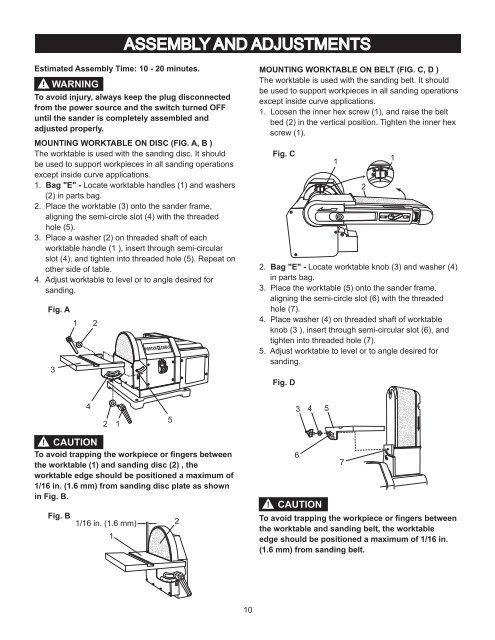
MOUNT<strong>IN</strong>G WORKTABLE ON <strong>DISC</strong> (FIG. A, B )<br />
The worktable is used with the sanding disc. It should<br />
be used to support workpieces in all sanding operations<br />
except inside curve applications.<br />
1. Bag "E" - Locate worktable handles (1) and washers<br />
(2) in parts bag.<br />
2. Place the worktable (3) onto the sander frame,<br />
aligning the semi-circle slot (4) with the threaded<br />
hole (5).<br />
3. Place a washer (2) on threaded shaft of each<br />
worktable handle (1 ), insert through semi-circular<br />
slot (4), and tighten into threaded hole (5). Repeat on<br />
other side of table.<br />
4. Adjust worktable to level or to angle desired for<br />
sanding.<br />
Fig. A<br />
1<br />
3<br />
! CAUTION<br />
To avoid trapping the workpiece or fingers between<br />
the worktable (1) and sanding disc (2) , the<br />
worktable edge should be positioned a maximum of<br />
1/16 in. (1.6 mm) from sanding disc plate as shown<br />
in Fig. B.<br />
Fig. B<br />
4<br />
2<br />
2 1<br />
1/16 in. (1.6 mm)<br />
1<br />
ON<br />
OFF<br />
5<br />
2<br />
10<br />
MOUNT<strong>IN</strong>G WORKTABLE ON <strong>BELT</strong> (FIG. C, D )<br />
The worktable is used with the sanding belt. It should<br />
be used to support workpieces in all sanding operations<br />
except inside curve applications.<br />
1. Loosen the inner hex screw (1), and raise the belt<br />
bed (2) in the vertical position. Tighten the inner hex<br />
screw (1).<br />
Fig. C<br />
2. Bag "E" - Locate worktable knob (3) and washer (4)<br />
in parts bag.<br />
3. Place the worktable (5) onto the sander frame,<br />
aligning the semi-circle slot (6) with the threaded<br />
hole (7).<br />
4. Place washer (4) on threaded shaft of worktable<br />
knob (3 ), insert through semi-circular slot (6), and<br />
tighten into threaded hole (7).<br />
5. Adjust worktable to level or to angle desired for<br />
sanding.<br />
Fig. D<br />
3 4<br />
6<br />
5<br />
1<br />
7<br />
!<br />
CAUTION<br />
To avoid trapping the workpiece or fingers between<br />
the worktable and sanding belt, the worktable<br />
edge should be positioned a maximum of 1/16 in.<br />
(1.6 mm) from sanding belt.<br />
2<br />
1