4 IN. x 8 IN. (102 MM x 203 MM) BELT / DISC SANDER PONCEUSE ...
4 IN. x 8 IN. (102 MM x 203 MM) BELT / DISC SANDER PONCEUSE ...
4 IN. x 8 IN. (102 MM x 203 MM) BELT / DISC SANDER PONCEUSE ...

Create successful ePaper yourself
Turn your PDF publications into a flip-book with our unique Google optimized e-Paper software.
!<br />
WARN<strong>IN</strong>G<br />
• For your safety, turn switch OFF and remove<br />
the power cord from the electrical outlet before<br />
adjusting or performing maintenance on your<br />
sander.<br />
• To avoid electric shock or fi re, all repairs to<br />
the electrical components should be done by<br />
a qualifi ed service technician. Before each use<br />
check for damaged, missing, or worn parts;<br />
check for alignment of moving parts, binding,<br />
improper mounting, or any other conditions<br />
that may affect the operation. Should any of<br />
these conditions exist, do not use the sander<br />
until properly repaired or parts are replaced.<br />
Frequently blow or vacuum dust from all sander<br />
parts and motor housing.<br />
REPLAC<strong>IN</strong>G SAND<strong>IN</strong>G <strong>DISC</strong> (FIG. S, T)<br />
!<br />
WARN<strong>IN</strong>G<br />
To avoid injury, turn switch OFF and disconnect the<br />
plug from the power source before removing and<br />
installing sanding belt.<br />
A sanding disc is pre-mounted at the factory. Use<br />
only sanding discs that measures 8 in.<br />
(<strong>203</strong> mm) in diameter.<br />
1. Remove the disc worktable, and then remove the<br />
disc cover (1) by removing six screws (2).<br />
2. Remove the existing disc, and clean any residue left<br />
on disc plate (3). Only use mineral spirits to remove<br />
this residue.<br />
Fig. S<br />
3. Peel the plastic (4) back from new sanding disc (5)<br />
and carefully press sanding disc fi rmly in position<br />
around the sanding plate. Make sure the disc is<br />
centered on the plate.<br />
4. Reinstall the disc cover, tighten screws and place<br />
sanding table back on unit.<br />
Fig. T<br />
3<br />
2<br />
1<br />
ON<br />
OFF<br />
5<br />
4<br />
MA<strong>IN</strong>TENANCE<br />
16<br />
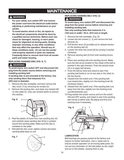
REPLAC<strong>IN</strong>G SAND<strong>IN</strong>G <strong>BELT</strong> (FIG. U)<br />
! WARN<strong>IN</strong>G<br />
To avoid injury, turn switch OFF and disconnect the<br />
plug from the power source before removing and<br />
installing sanding belt.<br />
Use only sanding belts that measures 4 in.<br />
(<strong>102</strong> mm) in width / 36 in. (914 mm) in length.<br />
1. Remove the belt worktable. (Fig. D)<br />
2. Loosen the two screws (1, 2) and remove the belt<br />
exhaust (3).<br />
3. Pull tension lever (4) pivotally out to release tension<br />
on the sanding belt (5).<br />
4. Loosen the inner hex screw (6) by turning it counterclockwise.<br />
5. Remove sanding belt (5) from both sanding drums<br />
(7).<br />
6. Place new sanding belt over sanding drums. Make<br />
sure the belt arrow located on the inside of the belt is<br />
pointed in the right direction. Push the tension lever<br />
(4) in to apply belt tension<br />
7. Push the belt by hand and check to see if the<br />
sanding belt tends to run to one side or the other on<br />
the two drums.<br />
8. Viewed from the switch end, if the sanding belt<br />
runs toward disc, slightly turn the tracking knob (8)<br />
clockwise (down).<br />
9. Viewed from the switch end, if the sanding belt runs<br />
away from the disc, slightly turn the tracking knob<br />
counterclockwise (up).<br />
10.Plug sander into power source and turn the switch<br />
ON and OFF quickly, and check to see if the sanding<br />
belt moves to either side. Re-adjust and fi ne tune<br />
tracking knob if necessary.<br />
Fig. U<br />
3<br />
6<br />
2<br />
5<br />
1 4<br />
LUBRICATION<br />
Ball bearings are grease packed at the factory and<br />
require no further lubrication. Use a paste wax to<br />
ensure smooth operation on all moving table parts. Do<br />
not use any lubrication on the belt platen as this might<br />
end up on the wheels, causing them to slip.<br />
7<br />
8