4 IN. x 8 IN. (102 MM x 203 MM) BELT / DISC SANDER PONCEUSE ...
4 IN. x 8 IN. (102 MM x 203 MM) BELT / DISC SANDER PONCEUSE ...
4 IN. x 8 IN. (102 MM x 203 MM) BELT / DISC SANDER PONCEUSE ...

Create successful ePaper yourself
Turn your PDF publications into a flip-book with our unique Google optimized e-Paper software.
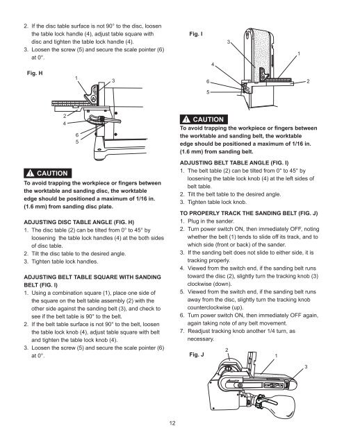
2. If the disc table surface is not 90° to the disc, loosen<br />
the table lock handle (4), adjust table square with<br />
disc and tighten the table lock handle (4).<br />
3. Loosen the screw (5) and secure the scale pointer (6)<br />
at 0°.<br />
Fig. H<br />
!<br />
2<br />
4<br />
CAUTION<br />
1<br />
6<br />
5<br />
To avoid trapping the workpiece or fingers between<br />
the worktable and sanding disc, the worktable<br />
edge should be positioned a maximum of 1/16 in.<br />
(1.6 mm) from sanding disc plate.<br />
ADJUST<strong>IN</strong>G <strong>DISC</strong> TABLE ANGLE (FIG. H)<br />
1. The disc table (2) can be tilted from 0° to 45° by<br />
loosening the table lock handles (4) at the both sides<br />
of disc table.<br />
2. Tilt the disc table to the desired angle.<br />
3. Tighten table lock handles.<br />
ADJUST<strong>IN</strong>G <strong>BELT</strong> TABLE SQUARE WITH SAND<strong>IN</strong>G<br />
<strong>BELT</strong> (FIG. I)<br />
1. Using a combination square (1), place one side of<br />
the square on the belt table assembly (2) with the<br />
other side against the sanding belt (3), and check to<br />
see if the belt table is 90° to the belt.<br />
2. If the belt table surface is not 90° to the belt, loosen<br />
the table lock knob (4), adjust table square with belt<br />
and tighten the table lock knob (4).<br />
3. Loosen the screw (5) and secure the scale pointer (6)<br />
at 0°.<br />
3<br />
12<br />
Fig. I<br />
! CAUTION<br />
To avoid trapping the workpiece or fingers between<br />
the worktable and sanding belt, the worktable<br />
edge should be positioned a maximum of 1/16 in.<br />
(1.6 mm) from sanding belt.<br />
ADJUST<strong>IN</strong>G <strong>BELT</strong> TABLE ANGLE (FIG. I)<br />
1. The belt table (2) can be tilted from 0° to 45° by<br />
loosening the table lock knob (4) at the left sides of<br />
belt table.<br />
2. Tilt the belt table to the desired angle.<br />
3. Tighten table lock knob.<br />
TO PROPERLY TRACK THE SAND<strong>IN</strong>G <strong>BELT</strong> (FIG. J)<br />
1. Plug in the sander.<br />
2. Turn power switch ON, then immediately OFF, noting<br />
whether the belt (1) tends to slide off its track, and to<br />
which side (front or back) of the sander.<br />
3. If the sanding belt does not slide to either side, it is<br />
tracking properly.<br />
4. Viewed from the switch end, if the sanding belt runs<br />
toward the disc (2), slightly turn the tracking knob (3)<br />
clockwise (down).<br />
5. Viewed from the switch end, if the sanding belt runs<br />
away from the disc, slightly turn the tracking knob<br />
counterclockwise (up).<br />
6. Turn power switch ON, then immediately OFF again,<br />
again taking note of any belt movement.<br />
7. Readjust tracking knob another 1/4 turn, as<br />
necessary.<br />
Fig. J<br />
6<br />
5<br />
4<br />
2<br />
3<br />
1<br />
1<br />
3<br />
2