Trumatic S 2200 / S 2200 P - Truma Gerätetechnik GmbH & Co. KG
Trumatic S 2200 / S 2200 P - Truma Gerätetechnik GmbH & Co. KG
Trumatic S 2200 / S 2200 P - Truma Gerätetechnik GmbH & Co. KG

Create successful ePaper yourself
Turn your PDF publications into a flip-book with our unique Google optimized e-Paper software.
The flue gas pipe with insulating duct and combustion<br />
air pipe must be rising over its entire<br />
length and protected from any modifications with double<br />
support DSW (installation variants B + C) as shown in fig. G1.<br />
A water trap may otherwise develop, obstructing the<br />
free passage of the exhaust gases!<br />
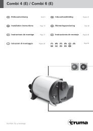
Duct connection to the cowls<br />
Fig. G3<br />
Position the heater in the chosen location, lead the ducts up to<br />
the cowl openings and determine required duct lengths. Slide<br />
the heater to the wall in such a way that the ducts project out<br />
of the wall approx. 4 cm.<br />
18<br />
The exhaust duct (2) with insulating duct (7) is positioned<br />
over the combustion air intake duct (8)!<br />
Slide sealing washers (10) approx. 3 cm up the ducts. Stretch<br />
open Orings (5) and pass over the cut edges of the ducts and<br />
insert ducts (2) and (8) into the cowls (11 + 12) as far as the<br />
stops (cowl connection fittings must be pointing down). Slide<br />
sealing washers with the O-rings right up and tighten securely<br />
with 2 screws (13) respectively.<br />
Always install a new O-ring (5) after any disassembly<br />
work!<br />
Fastening the cowls<br />
Fig. G3<br />
<strong>Co</strong>at exhaust gas cowl (11) with plastic sealant on the sealing<br />
surface (do not use silicone!) and slide into the upper<br />
cowl opening (the cowl connection fitting must be pointing<br />
down). Fasten exhaust cowl (11) and cowl plate (14) using<br />
4 screws (15).<br />
Fasten combustion air cowl (12) in the same manner, in the<br />
lower cowl opening, together with the intake grille (16).<br />
Always mount cover caps (17) for the cowls when the heater<br />
is not being used (accessories).<br />
Exhaust routing via the roof (cowl kit AKD)<br />
Only <strong>Truma</strong> stainless steel flue gas pipe AE 3 may be used<br />
with the <strong><strong>Truma</strong>tic</strong> S <strong>2200</strong> (Part no. 30140-00) with <strong>Truma</strong><br />
insulating duct ÜR (APP – Part no. 40230-00), since the heater<br />
has only been tested and approved in combination with these<br />
pipes. Total length of the exhaust gas duct: max. 3 m!<br />
Fig. F<br />
Fitting and bending the stainless steel duct and stretching<br />
open the O-ring are facilitated considerably using the “Biege-<br />
Boy“ (part no. 30030-33000).<br />
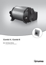
Assembly of combustion air intake<br />
1. Fig. H1<br />
Release the two screws (1) on the top of the heater and<br />
remove casing.<br />
2. Fig. H2<br />
Prior to installation of the heater, Install the elbow for the<br />
combustion air intake on the lower heater connection fitting<br />
as follows: Slide elbow (18) with the cut edge of the pipe from<br />
the bottom, through the opening (19) in the heater base. Slide<br />
sealing plate (4) approx. 3 cm up the pipe (claw pointing towards<br />
heater connection fitting). Stretch open O-ring (5) and<br />
carefully pass it over the cut edge of the pipe and insert elbow<br />
into the lower heater connection fitting (9). Slide the sealing<br />
plate right up with the O-ring and engage by turning, Tighten<br />
with screw (6).<br />
Always install a new O-ring (5) after any disassembly<br />
work!<br />
3. Install heater into the floor opening.<br />
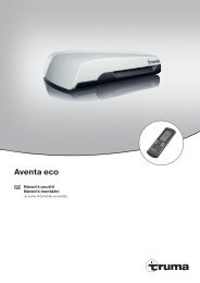
Assembly of roof cowl<br />
The roof cowl is only to be installed vertically or with an max.<br />
incline of 15 degrees!<br />
Fig. H3<br />
Position the roof cowl so that the duct (maximum length 3 m!)<br />
can be routed direct from the heater, sloping upward all the<br />
way to the cowl. A 1.5 metres long duct must reach a height<br />
of at least 1 metre.<br />
1. Fig. H4<br />
Cut out an opening with a Ø of 60 mm at a centre distance of<br />
at least 55 mm from the side walls. In the case of a doubleskin<br />
roof, line the cavity with wood or slide in a rolled circular<br />
sheet metal strip (20) of about 220 mm in length and 1 mm<br />
in thickness, to stiffen the roof so that when the screws are<br />
tightened it does not warp and stays weatherproof.<br />
2. Push the cowl through the roof from above and fasten it on<br />
the inside with retention ring (21).<br />
Use the enclosed rubber sealing ring without further sealing<br />
materials.