Gebrauchsanleitung Manual Mode d'Emploi
Gebrauchsanleitung Manual Mode d'Emploi
Gebrauchsanleitung Manual Mode d'Emploi

Create successful ePaper yourself
Turn your PDF publications into a flip-book with our unique Google optimized e-Paper software.
The integral contact connected to the two red<br />
wires can be used for switching the track power<br />
and therefore for automatic train control.<br />
Programming of the address<br />
Every digital device requires an address in order<br />
to allow the command control station or any other<br />
input device to send specifi c commands. The<br />
desired address has to be programmed. In order<br />
to do this, connect the signal to the digital system<br />
temporarily. Now you have to switch the decoder<br />
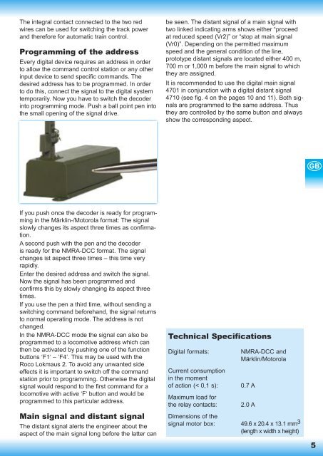
into programming mode. Push a ball point pen into<br />
the small opening of the signal drive.<br />
If you push once the decoder is ready for programming<br />
in the Märklin-/Motorola format: The signal<br />
slowly changes its aspect three times as confi rmation.<br />
A second push with the pen and the decoder<br />
is ready for the NMRA-DCC format. The signal<br />
changes ist aspect three times – this time very<br />
rapidly.<br />
Enter the desired address and switch the signal.<br />
Now the signal has been programmed and<br />
confi rms this by slowly changing its aspect three<br />
times.<br />
If you use the pen a third time, without sending a<br />
switching command beforehand, the signal returns<br />
to normal operating mode. The address is not<br />
changed.<br />
In the NMRA-DCC mode the signal can also be<br />
programmed to a locomotive address which can<br />
then be activated by pushing one of the function<br />
buttons ‘F1‘ – ‘F4‘. This may be used with the<br />
Roco Lokmaus 2. To avoid any unwanted side<br />
effects it is important to switch off the command<br />
station prior to programming. Otherwise the digital<br />
signal would respond to the fi rst command for a<br />
locomotive with active ‘F‘ button and would be<br />
programmed to this particular address.<br />
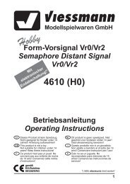
Main signal and distant signal<br />
The distant signal alerts the engineer about the<br />
aspect of the main signal long before the latter can<br />
be seen. The distant signal of a main signal with<br />
two linked indicating arms shows either “proceed<br />
at reduced speed (Vr2)” or “stop at main signal<br />
(Vr0)”. Depending on the permitted maximum<br />
speed and the general condition of the line,<br />
prototype distant signals are located either 400 m,<br />
700 m or 1,000 m before the main signal to which<br />
they are assigned.<br />
It is recommended to use the digital main signal<br />
4701 in conjunction with a digital distant signal<br />
4710 (see fi g. 4 on the pages 10 and 11). Both signals<br />
are programmed to the same address. Thus<br />
they are controlled by the same button and always<br />
show the corresponding aspect.<br />
Technical Specifications<br />
Digital formats: NMRA-DCC and<br />
Märklin/Motorola<br />
Current consumption<br />
in the moment<br />
of action (< 0,1 s): 0.7 A<br />
Maximum load for<br />
the relay contacts: 2.0 A<br />
Dimensions of the<br />
signal motor box: 49.6 x 20.4 x 13.1 mm 3<br />
(length x width x height)<br />
GB<br />
5