UltraSmart IUC-4100E, IUC-5100E - Innotek
UltraSmart IUC-4100E, IUC-5100E - Innotek
UltraSmart IUC-4100E, IUC-5100E - Innotek

Create successful ePaper yourself
Turn your PDF publications into a flip-book with our unique Google optimized e-Paper software.
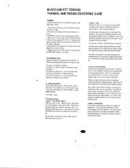
Customized Loops. You can create off limit areas, such as<br />
pools and gardens by encircling the area with wire. Run<br />
twisted wire from the fence loop to the encircled area, and<br />
splice the ends together.<br />
splices<br />
Customized Loops<br />
splices<br />
splices<br />
2. Rounding Corners<br />
Use gradual turns at the corners with a minimum of 0.8m<br />
radius.This will produce a more consistent pet fencing field.<br />
3. Placing the wire<br />
The wire must make a continuous loop from the<br />
transmitter and back again. The signal passes from one<br />
transmitter terminal around the loop and back to the<br />
transmitter again. Keep in the mind that you will want an<br />
3-4m pet fencing signal field from your wire, so don't run<br />
the wire too close to the house and make passageways too<br />
narrow for your dog to pass.<br />
4. Twisted Wire<br />
Twisted wire cancels the radio signal coming from your<br />
transmitter. This enables your dog to cross over the wire in<br />
the safe part of the yard. Where there is single wire, the<br />
fence is active and your dog will be unable to pass. Your kit<br />
may have come with FasTrak pre-twisted wire or you can<br />
purchase it as a separate kit.<br />
You can twist your own wire by cutting two equal lengths<br />
of wire supplied and twisting them together. Anchor one<br />
end of the wires to something secure and insert the other<br />
end in a power drill. Pull wire taut. The drill enables you to<br />
twist the wire quickly. You will need at least 12 twists per<br />
30cm to effectively cancel the radio signal.<br />
IMPORTANT TIPS<br />
DO NOT run wire within 3m or parallel to cable TV, phone<br />
or electrical lines. The signals can couple together, causing<br />
inadvertent collar activation in the house and safe parts of<br />
the yard.<br />
The wire must form one continuous loop from the<br />
transmitter.<br />
8<br />
Work carefully. A nick in the wire can diminish signal<br />
strength and create a weak area where your dog can<br />
escape.<br />
Use twisted wire to run between the transmitter and the<br />
interior loops, such as around pools and gardens. This will<br />
allow your dog to safely pass around these areas.<br />
(Reference Custom Loop illustration.)<br />
Step 4<br />
Final Connections<br />
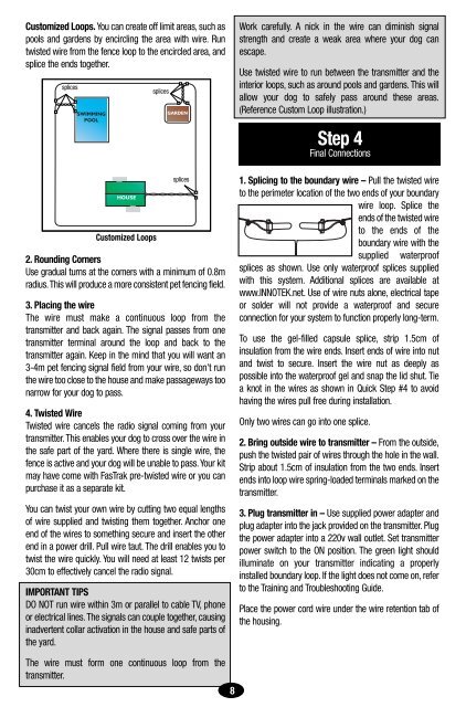
1. Splicing to the boundary wire – Pull the twisted wire<br />
to the perimeter location of the two ends of your boundary<br />
wire loop. Splice the<br />
ends of the twisted wire<br />
to the ends of the<br />
boundary wire with the<br />
supplied waterproof<br />
splices as shown. Use only waterproof splices supplied<br />
with this system. Additional splices are available at<br />
www.INNOTEK.net. Use of wire nuts alone, electrical tape<br />
or solder will not provide a waterproof and secure<br />
connection for your system to function properly long-term.<br />
To use the gel-filled capsule splice, strip 1.5cm of<br />
insulation from the wire ends. Insert ends of wire into nut<br />
and twist to secure. Insert the wire nut as deeply as<br />
possible into the waterproof gel and snap the lid shut. Tie<br />
a knot in the wires as shown in Quick Step #4 to avoid<br />
having the wires pull free during installation.<br />
Only two wires can go into one splice.<br />
2. Bring outside wire to transmitter – From the outside,<br />
push the twisted pair of wires through the hole in the wall.<br />
Strip about 1.5cm of insulation from the two ends. Insert<br />
ends into loop wire spring-loaded terminals marked on the<br />
transmitter.<br />
3. Plug transmitter in – Use supplied power adapter and<br />
plug adapter into the jack provided on the transmitter. Plug<br />
the power adapter into a 220v wall outlet. Set transmitter<br />
power switch to the ON position. The green light should<br />
illuminate on your transmitter indicating a properly<br />
installed boundary loop. If the light does not come on, refer<br />
to the Training and Troubleshooting Guide.<br />
Place the power cord wire under the wire retention tab of<br />
the housing.