CUCINOTTA / CUCINOTTA FORNO
CUCINOTTA / CUCINOTTA FORNO
CUCINOTTA / CUCINOTTA FORNO

Create successful ePaper yourself
Turn your PDF publications into a flip-book with our unique Google optimized e-Paper software.
<strong>CUCINOTTA</strong> – <strong>CUCINOTTA</strong> Forno<br />
4.1. FIRST-AID MEASURES<br />
Should any fire arise in the stack or in the flue:<br />
a) Close the feeding door and the ash drawer door.<br />
b) Close the registers of combustion air<br />
c) Extinguish the fire using carbon dioxide fire-fighting means (CO2 dust).<br />
d) Seek immediate intervention of FIRE BRIGADE.<br />
DO NOT EXTINGUISH FIRE USING WATER JETS<br />
When the fire has been extinguished, let the flue check by an expert to find possible cracks and permeable<br />
points.<br />
5. FLUE<br />
Essential requirements for a correct operation of the device:<br />
• the internal section must be preferably circular;<br />
• be thermally insulated and water-proof and produced with<br />
materials suitable to resist to heat, combustion products and<br />
possible condensates;<br />
• not be throttled and show a vertical arrangement with<br />
deviations not greater than 45°;<br />
• if already used, it must be clean;<br />
• observe the technical data of the instructions manual;<br />
Should the flues have a square or rectangular section, internal edges<br />
must be rounded with a radius not lower than 20 mm. For the<br />
rectangular section, the maximum ratio between the sides must be ≤<br />
1.5.<br />
A too small section causes a decrease of the draught. It is suggested<br />
a minimum height of 4 m.<br />
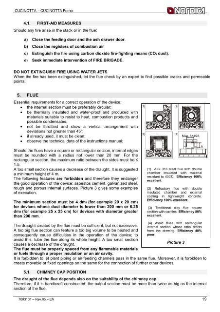
The following features are forbidden and therefore they endanger<br />
the good operation of the device: asbestos cement, galvanized steel,<br />
rough and porous internal surfaces. Picture 3 gives some examples<br />
of execution.<br />
The minimum section must be 4 dm2 (for example 20 x 20 cm)<br />
for devices whose duct diameter is lower than 200 mm or 6.25<br />
dm2 (for example 25 x 25 cm) for devices with diameter greater<br />
than 200 mm.<br />
The draught created by the flue must be sufficient, but not excessive.<br />
A too big flue section can feature a too big volume to be heated and<br />
consequently cause difficulties in the operation of the device; to<br />
avoid this, tube the flue along its whole height. A too small section<br />
causes a decrease of the draught.<br />
The flue must be properly spaced from any flammable materials<br />
or fuels through a proper insulation or an air cavity.<br />
It is forbidden to let plant piping or air feeding channels pass in the same flue. Moreover, it is forbidden to<br />
create movable or fixed openings on the same for the connection of further other devices.<br />
5.1. CHIMNEY CAP POSITION<br />
(1) (2)<br />
(1) AISI 316 steel flue with double<br />
chamber insulated with material<br />
resistant to 400°C. Efficiency 100%<br />
excellent.<br />
(2) Refractory flue with double<br />
insulated chamber and external<br />
coating in lightweight concrete.<br />
Efficiency 100% excellent.<br />
(3) Traditional clay flue square<br />
section with cavities. Efficiency 80%<br />
excellent.<br />
(4) Avoid flues with rectangular<br />
internal section whose ratio differs<br />
from the drawing. Efficiency 40%<br />
poor.<br />
Picture 3<br />
Max. A+1/2A<br />
A+1/2A<br />
The draught of the flue depends also on the suitability of the chimney cap.<br />
Therefore, if it is handicraft constructed, the output section must be more than twice as big as the internal<br />
section of the flue.<br />
7093101 – Rev.05 – EN 19<br />
(3)<br />
(4)<br />
A