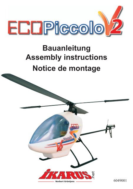
Eco Piccolo V2 6049001.indd - Ikarus
Eco Piccolo V2 6049001.indd - Ikarus
Eco Piccolo V2 6049001.indd - Ikarus

Create successful ePaper yourself
Turn your PDF publications into a flip-book with our unique Google optimized e-Paper software.
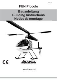
Bauanleitung<br />
Assembly instructions<br />
Notice de montage<br />
6049001
Danke...<br />
Mit dem ECO <strong>Piccolo</strong> <strong>V2</strong>, haben Sie einen R/C-<br />
Elektro-Modellhelicopter auf dem neuesten Stand<br />
der Technik erworben. Die Verwendung modernster<br />
Technologien und Produktionsprozesse bietet<br />
hervorragende Leistung und beste Flugzeiten. Das<br />
macht den <strong>Piccolo</strong> auch zu einem Outdoor-<br />
Helicopter für ruhigere Windverhältnisse.<br />
Montieren Sie das Modell so sorgfältig wie<br />
möglich.<br />
Sie benötigen...<br />
(Nicht im Bausatz # 6041001 / 6041002 enthalten)<br />
Best. Nr.: Beschreibung<br />
720535 Piccoboard Plus 35 Mhz<br />
oder 720540 Piccoboard Plus 40 Mhz<br />
171202 Micro Servo 202 (2x)<br />
173401 Sender 35MHz<br />
oder 173402 Sender 40/41MHz<br />
67492 8-Zellen Akku 9,6 V (NiMH)<br />
für ca 7 Min. Flugzeiten<br />
8023002 Ladegerät für NiMH-Akku 230V<br />
8023001 Ladegerät 110 V<br />
2027004 3-Zellen Akku 11,1 V (LiPoly)<br />
für ca.30 Min. Flugzeiten<br />
2027011 Ladegerät für LiPoly-Akku<br />
Technische Daten:<br />
Hauptrotor-Durchmesser: 500 mm<br />
Rumpflänge: 500 mm<br />
Fluggewicht: ca. 280 g<br />
Flugakku: 7 - 12 Volt<br />
Werkzeuge:<br />
Zur Montage benötigen Sie zusätzlich<br />
- Ein scharfes Messer<br />
- Eine kleine Spitzzange<br />
Symbole...<br />
Um Ihre Aufmerksamkeit auf bestimmte Vorgänge<br />
zu lenken, haben wir Symbole benutzt, die folgende<br />
Bedeutung haben:<br />
2<br />
!<br />
Hier ist besondere Sorgfalt nötig<br />
Verwenden Sie Cyanacrylat- (CA-) Kleber<br />
WARNHINWEIS!:<br />
Cyanacrylat (CA)-Kleber klebt innerhalb von Sekunden<br />
Haut und Augen zusammen. Bei Augenkontakt<br />
sofort mit Wasser spülen, Arzt aufsuchen. Darf nicht<br />
in die Hände von Kindern gelangen. Dampf nicht<br />
einatmen. Nur in gut belüfteten Bereichen verwenden.<br />
Garantie...<br />
Wir garantieren, für eine Zeit von 12 Monaten nach<br />
dem Kauf, dass dieser Bausatz frei von Fabrikations-<br />
oder Materialfehlern ist. Schäden durch<br />
falschen Gebrauch oder Montagefehler werden<br />
durch diese Garantie nicht gedeckt. Sobald der Hubschrauber<br />
in Betrieb genommen wird, übernimmt<br />
der Benutzer alle daraus erwachsende Verantwortlichkeit.<br />
Allgemeines:<br />
Dieser Hubschrauber ist aufgrund seiner völlig neu<br />
entwickelten Mechanik, der Elektronik und des<br />
Rumpfsystemes etwas Besonderes.<br />
Beachten Sie die Hinweise zum Justieren. Desweiteren<br />
hat CA-Kleber die Eigenschaft, in enge Spalten<br />
zu fließen, arbeiten Sie damit also bitte immer<br />
sparsam und sorgfältig!<br />
Übrigens...<br />
können Sie den fertig gebauten <strong>Piccolo</strong> mit dem<br />
Bausatzkoffer leicht transportieren.<br />
IKARUS WÜNSCHT IHNEN VIEL SPASS BEIM<br />
FLIEGEN DES PICCOLO
Montage Chassis<br />
Kleben Sie mit einem Tropfen CA-Kleber die<br />
Kabinenhalterung # 67380 mittig auf das Chassis #<br />
68245. Jetzt wird das Kufenlandegestell zusammen<br />
geclipst. Clipsen Sie nun die Kufen # 67465 in den<br />
vorderen und hinteren Kufenbügel # 67464 gemäß<br />
Zeichnung. Das Kufenlandegestell wird nun erst<br />
vorne in die Tasche des Chassis gedrückt bis es einclipst.<br />
Danach der hintere Kufenbügel, da ist darauf<br />
zu achten, dass die vorderen kleinen Nasen in die<br />
Langlöcher einrasten.<br />
Schieben Sie das Hauptzahnrad # 67372 auf die<br />
Haupt-Rotorwelle # 67382 und drücken Sie den<br />
kürzeren Stift # 67399 mit einer Zange durch die<br />
Bohrungen von Zahnrad und Welle. Drücken Sie die<br />
beiden Lager # 67571 ins Gehäuse, schieben die<br />
Rotorwelle durch und fixieren sie von oben mit der<br />
Gummitülle # 67385.<br />
3
Montage Chassis<br />
4<br />
<br />
<br />
<br />
<br />
Bevor Sie mit der Montage des Motors beginnen,<br />
sollten Sie den Motor einlaufen lassen. Dadurch<br />
können Sie die Lebensdauer und die Leistung deutlich<br />
verbessern. Sofern Sie nicht das Original-<strong>Ikarus</strong>-<br />
Piccoboard verwenden, kann ein nicht eingelaufener<br />
Motor u.U., bedingt durch eine starke Funkenbildung,<br />
Störungen auf den Empfänger übertragen.<br />
Die Folge wäre ein zeitweises leichtes Zucken der<br />
Servos.<br />
Einlaufen des Motors:<br />
Nehmen Sie Ihre Fernsteuerungsanlage in Betrieb.<br />
Schalten Sie zunächst den Sender ein und stellen<br />
den Gasknüppel auf Leerlaufposition. Verbinden<br />
Sie den Motor mit dem Piccoboard. Achten Sie<br />
bitte darauf, dass das Piccoboard richtig gesteckt ist<br />
(siehe Anleitung Piccoboard). Stecken Sie dann einen<br />
geladenen Flugakku am Piccoboard ein. Nachdem<br />
die rote LED am Piccoboard aufleuchtet, geben<br />
Sie 1/4 Gas und lassen den Motor so (ohne Last)<br />
einlaufen, bis der Akku leer ist. Wiederholen Sie die<br />
Einlaufphase 2-3 mal.<br />
Befestigen Sie den Motor mit den beiden Schrauben<br />
M 3x8 # 67605 in den Langlöchern so, dass das<br />
Getriebe nicht zu stramm läuft, sondern ein wenig<br />
Spiel hat. Schieben Sie dazu einen Papierstreifen<br />
zwischen die Zahnräder, drücken den Motor nach<br />
hinten und ziehen zunächst die vordere, dann die<br />
hintere Schraube mit Gefühl an. Ziehen Sie danach<br />
den Papierstreifen heraus. Die leichtgängige Justierung<br />
ist für Flugzeit und Lebensdauer wichtig.
langer Arm<br />
<br />
<br />
<br />
<br />
<br />
Scharfkantig<br />
kurzer Arm<br />
<br />
<br />
Gerundet<br />
<br />
<br />
Montage Rotorkopf<br />
Die Kugelclips sind die wichtigsten Verbindungselemente<br />
für die Steuerung des Hubschraubers. Sie sollen<br />
sich spielfrei, aber leichtgängig bewegen lassen.<br />
Aufgrund von Fertigungstoleranzen kann dies<br />
werkseitig nicht zufriedenstellend voreingestellt werden.<br />
Deshalb sind die Clipse von uns so ausgelegt,<br />
dass sie eher etwas zu schwergängig sind. Dies<br />
lässt sich nämlich schnell und einfach nachjustieren.<br />
Drücken Sie dazu einen Kugelclip auf die zugehörige<br />
Kugel. Dabei zeigt die scharfkantige Seite des<br />
Ringes um den Clip immer zur Kugel. Schwenken<br />
Sie ihn dann in alle Richtungen. Wenn Sie merken,<br />
dass sich der Clip nicht leichtgängig und ruckfrei<br />
bewegen lässt, drücken Sie mit einer kleinen Zange<br />
den Clip vorsichtig auf der Kugel zusammen. Fangen<br />
Sie bitte mit wenig Druck an, prüfen dann wieder die<br />
Beweglichkeit, drücken nochmal und so fort, bis sich<br />
der Clip leichtgängig schwenken lässt. Verfahren Sie<br />
so bitte nacheinander mit allen Kugelclips. Die Zuordnung,<br />
welcher Clip zu welcher Kugel gehört, können<br />
Sie der Abbildung entnehmen.<br />
Die Taumelscheibe ist bereits vormontiert. Schieben<br />
Sie die Taumelscheibe # 67462 auf die Rotorwelle #<br />
67382, stecken Sie das Zentralstück # 67369 auf und<br />
drücken den längeren Stift # 67400 mit einer Zange<br />
durch die Bohrungen von Welle und Zentralstück.<br />
Der Stift muss mittig im Zentralstück sitzen.<br />
Der Sicherungsclip # 68215 wird zunächst nur über<br />
das Zentralstück gefädelt und anschließend die beiden<br />
Kugellager 2x6x3 # 67566 auf das Zentralstück<br />
gesteckt. Clipsen Sie dann den Rotorkopf<br />
# 67370 auf die Kugellager. Schieben Sie nun den<br />
Sicherungsclip nach oben, bis beide Sicherungshaken<br />
hörbar am Rotorkopf nach außen einschnappen.<br />
Nach dem Einschnappen hat der Kopf auf den<br />
Lagern etwas Spiel, dies ist beabsichtigt. Biegen Sie<br />
den Taumelscheibenmitnehmer # 67366 mit zwei<br />
Fingern vor, so dass er in etwa die abgebildete Form<br />
annimmt. Stecken Sie dann den Mitnehmer zunächst<br />
von oben auf den Stift, verbiegen ihn dann vorsichtig<br />
und stecken die andere Seite von unten auf. Clipsen<br />
Sie das Kugelgelenk an einen der kurzen Arme des<br />
Innenrings der Taumelscheibe. Die scharfkantige<br />
Seite des Clips zeigt dabei zur Kugel.<br />
5
Montage Rotorkopf<br />
Stecken Sie die Paddelstange # 67474 durch den<br />
Rotorkopf, schieben dann die Anlenkhebel # 67368<br />
auf und fixieren sie mit den Schrauben M2x6/#<br />
67561 so, dass die Stabistange mittig sitzt und die<br />
beiden Anlenkhebel in einer Ebene liegen. Achten<br />
Sie bitte darauf, dass sich die Stabistange leicht drehen<br />
lässt, aber ein kleinstmögliches Längsspiel hat.<br />
6<br />
<br />
<br />
<br />
<br />
<br />
<br />
<br />
<br />
<br />
<br />
Schieben Sie nun die Gewichte # 67475 auf die Paddelstange. Je weiter die Gewichte nach außen montiert<br />
sind, desto träger wird das System.<br />
Wir empfehlen daher die Gewichte ca.<br />
1,5 cm von Innenkante Paddel auf der<br />
Paddelstange zu platzieren. Stecken<br />
Sie die Hillerpaddel # 68240 auf die<br />
Stabistange # 67474, bis diese bündig<br />
mit der Außenseite der Befestigungslasche<br />
der Paddel ist und verschrauben<br />
Sie. Achten Sie bitte darauf, dass<br />
die Paddel zueinander und mit den<br />
Anlenkhebeln in einer Ebene liegen.<br />
Diese Einstellung nehmen Sie bitte<br />
mit viel Sorgfalt vor, sie ist wichtig für<br />
die Flugeigenschaften. Der Rotorkopf kann jetzt in den Kugellagern pendeln. Stellen Sie den Hubschrauber<br />
gerade hin und beobachten Sie die Hillerstange. Neigt sich immer dasselbe Paddel nach unten, so prüfen<br />
Sie nochmal, ob der Abstand zur Mitte auf beiden Seiten gleich ist, und korrigieren Sie ihn gegebenenfalls.<br />
Bleibt die Unwucht, so kleben Sie etwas Tesafilm auf das Paddel, das sich hebt, bis beide genau in der<br />
Waage bleiben.<br />
Clipsen Sie die beiden Steuerstangen # 67367 in die Aufnahmen der Anlenkhebel und auf die längeren<br />
Arme des Taumelscheibeninnenrings. Auch hier zeigt die scharfkantige Seite des Clips wieder zur Kugel.
Pressen Sie jetzt den Heckpropeller # 67471 auf<br />
die Welle des Heckmotors # 67472. Achtung: der<br />
kegelförmige Ansatz der Propellernabe muß zum<br />
Motor zeigen, dabei ist zu beachten, dass zwischen<br />
Lagerschild vom Motor und dem Propeller Luft ist.<br />
Jetzt können Sie den Motor mit dem Propeller in das<br />
Heckgehäuse # 67467 schrauben.<br />
Legen Sie das Heckrohr in das Heckgehäuse.<br />
Beachten sie hierbei, dass das Heckrohr bis an den<br />
Anschlag eingelegt wird. Jetzt wird die Lasche nach<br />
oben geklappt und das Gehäuse mit der Schraube<br />
auf das Heckrohr geklemmt.<br />
Führen Sie das Kabel des Heckmotors durch das Heckrotorgehäuse, dann durch das Heckrohr und<br />
schließlich durch das Chassis. Kleben Sie das Heckrohr ins Chassis, wobei Sie das Rohr bis zum Anschlag<br />
einschieben. Achten Sie bitte darauf, dass die Heckpropeller exakt waagrecht (im rechten Winkel zur Hauptrotorwelle)<br />
positioniert sind, dann einen Tropfen CA-Kleber in den Spalt geben.<br />
Nun können Sie die Haube # 69010 noch mit dem Dekobogen # 6043001 verzieren.<br />
Montage Heckrotor<br />
7
RC- Einbau<br />
<br />
8<br />
<br />
<br />
<br />
<br />
67387<br />
<br />
67365<br />
Schneiden Sie zunächst mit einem scharfen Messer<br />
oder einem Seitenschneider an beiden Servos die<br />
Befestigungslaschen ab. Montieren Sie die Gestänge,<br />
indem Sie den Stahldraht zunächst mit dem Lförmigen<br />
Ende in den Clip # 67365 stecken und ihn<br />
dann um 90° schwenken, so dass er einschnappt.<br />
Stecken Sie die Servos (noch nicht die Motoren!) am<br />
Empfänger an und schließen Sie den Flugakku an.<br />
Stellen Sie die Trimmschieber am Sender in die<br />
Mitte. Jetzt stecken Sie die Servohebel in waagrechter<br />
Position auf die Servos und verschrauben<br />
sie. Nun werden die Gestänge mit dem Z-förmigen<br />
Ende in das äußere Loch des Servohebels gesteckt<br />
und nach oben geschwenkt. Wir beginnen mit dem<br />
Nickservo. Hier kommt das längere Gestänge an<br />
den Hebel. Drücken Sie nun den Clip wie gezeichnet<br />
auf die Kugel der Taumelscheibe. Jetzt halten Sie<br />
das Servo probehalber an die seitliche Klebefläche<br />
und verschieben es, bis die Taumelscheibe von der<br />
Seite gesehen senkrecht zur Rotorwelle steht. Wenn<br />
Sie diese Position haben, ziehen Sie das Servo<br />
etwas weg und geben CA-Kleber auf die Klebefläche.<br />
Drücken Sie das Servo in vorherigen Position<br />
wieder an. Sie können es dabei noch ca. 2-3 sec.<br />
verschieben.<br />
Nun wird das Rollservo montiert. Das kürzere<br />
Gestänge wird eingehängt, der Clip aufgedrückt und<br />
das Servo positioniert. Hierbei muss die Taumelscheibe<br />
in Flugrichtung gesehen senkrecht zur<br />
Rotorwelle stehen. Kleben Sie das Servo wie zuvor<br />
beschrieben ein. Um Ihnen zusätzlich zur Sendertrimmung<br />
eine weitere Trimmmöglichkeit zu geben,<br />
wurden die Gestänge # 67387 und # 67392 mit<br />
Ausgleichbögen versehen. Durch Aufbiegen oder<br />
Zusammendrücken dieser Ausgleichbögen können<br />
Sie die Gestängelängen leicht und bequem verändern.<br />
Bei zentrierten Sendertrimmungen können Sie<br />
die Taumelscheibe somit exakt austrimmen.<br />
Die Taumelscheibe steht nun in jeder Ebene senkrecht<br />
zur Rotorwelle. Bauen Sie jetzt das Piccoboard<br />
ein. Achtung: Verbinden Sie das Board noch nicht<br />
mit dem Akkupack! Bitte folgen Sie zunächst den<br />
weiteren Anweisungen zum Aufbau, insbesondere<br />
muss immer zuerst der Sender, dann der Empfänger<br />
eingeschaltet werden!<br />
Stecken Sie alle Anschlüsse außer dem Flugakku<br />
ein, legen Sie dann das Board auf den Vorbau, und<br />
zwar so, dass die Anschlüsse nach hinten und die<br />
LED in Flugrichtung nach links weisen. Alle Kabel<br />
müssen so verlegt werden, dass sie keinesfalls an<br />
bewegte Teile des Hubschraubers kommen können.<br />
Nun wird das Piccoboard mit dem doppelseitigen<br />
Klebeband befestigt.
Pitchwinkel<br />
<br />
<br />
<br />
<br />
<br />
Akku-Typ Empfehlung<br />
1 8 Zellen NiMh Schweben<br />
2 2 Zellen Lithiumpolymer Indoor / Rundflug<br />
3 3 Zellen Lithiumpolymer Outdoor / Rundflug<br />
Endmontage<br />
Als nächstes verlegen Sie dann die Empfangsantenne,<br />
indem Sie diese zu einer Kufe führen und dort<br />
mit Klebeband so fixieren, dass noch ca 10 cm der<br />
Antenne frei hängen können. Jetzt wird noch der<br />
Flugakku mit einem Gummiring unter dem Vorbau<br />
befestigt. Den Ring hängen Sie dazu seitlich an der<br />
Querstange ein. Durch Verschieben des Akkus nach<br />
vorne oder hinten wird der Schwerpunkt eingestellt.<br />
Dazu halten Sie den Hubschrauber an der Hillerstange,<br />
stellen diese quer zum Rumpf und beobachten<br />
die Kufen. Diese sollen genau parallel zu Ihrer<br />
Bauunterlage (Tisch) verlaufen. Verschieben Sie den<br />
Akku, bis dies erreicht ist. Nun wird die Kabinenhaube<br />
montiert. Schieben Sie die Haube von vorne auf<br />
das Modell und drücken Sie diese auf den Kabinenhalter<br />
bis die Haube einclipst.<br />
Als letztes fehlen nun noch die Rotorblätter # 67375.<br />
Diese werden mit Blechtreibschrauben # 67473 von<br />
unten in den Rotorkopf geschraubt. Sie können nun<br />
durch die Montage der Pitchwinkelscheiben die Drehzahl<br />
des Hubschraubers an Ihren Akku bzw. Flugstil<br />
anpassen. Entnehmen Sie die Flugcharakteristik mit<br />
den jeweils verwendeten Pitch-Einstellscheiben aus<br />
der nebenstehenden Tabelle.<br />
Die Wellenlinie auf dem Rotorblatt ist oben. Die<br />
Schrauben für die Rotorblätter dürfen nicht zu fest<br />
angezogen werden, nur soweit, dass die Rotorblätter<br />
durch ihr Eigengewicht gerade nicht mehr aus ihrer<br />
Position schwenken. Sind die Schrauben hier zu fest<br />
angezogen, kann der Hubschrauber in Vibrationen<br />
kommen, sind sie zu locker, ist das Hochfahren der<br />
Rotordrehzahl erschwert.<br />
Nun schalten Sie zuerst den Sender ein, stellen alle<br />
Trimmschieber auf Mitte und ziehen den Gas-Knüppel<br />
und die Gastrimmung in die tiefste Position. Erst<br />
danach wird der Flugakku ins Piccoboard eingesteckt.<br />
Lassen Sie den Hubschrauber solange ruhig<br />
stehen, bis die rote LED am Piccoboard aufleuchtet,<br />
das dauert ca. 5-7 sec. Die Elektronik ist jetzt aktiv.<br />
Bleiben Sie mit dem Gas in tiefster Position und<br />
führen Sie einen Rudercheck durch. Wenn Sie am<br />
Nickknüppel ziehen, muss sich die Taumelscheibe<br />
nach hinten neigen, bewegen Sie den Rollknüppel<br />
nach links, so neigt sich auch die Taumelscheibe<br />
nach links. Geben Sie nun langsam etwas Gas. Der<br />
Hauptrotor setzt sich in Bewegung und etwas später<br />
folgt der Heckrotor.<br />
Nun ist Ihr <strong>Piccolo</strong> <strong>V2</strong> zum Erstflug bereit !<br />
9
Das Fliegen<br />
10<br />
<br />
<br />
<br />
<br />
<br />
Der ECO <strong>Piccolo</strong> <strong>V2</strong> ist fertig aufgebaut, die Akkus<br />
(auch vom Sender!) sind geladen und nun soll der<br />
Hubschrauber zeigen, was in ihm steckt. Dazu<br />
benötigen wir zunächst ein Fluggelände. Ideal ist<br />
zum Beginn eine kleine Halle oder ein größerer<br />
Raum, möglichst ohne Hindernisse. Stellen Sie<br />
den <strong>Piccolo</strong> in die Mitte der freien Fläche. Wenn<br />
alles funktioniert, stellen Sie sich etwa 2 m hinter<br />
den Hubschrauber, leicht seitlich versetzt, um auch<br />
die Nase beobachten zu können. Dann geben Sie<br />
langsam Gas, bis der Hubschrauber anfängt, „leicht“<br />
zu werden, d. h. irgendeine Bewegung zu zeigen.<br />
(Gasgeben ist hier im übrigen ein etwas übertragener<br />
Begriff, eigentlich geben wir Volt). Beobachten<br />
Sie dabei zunächst vorne die Nase. Dreht er nach<br />
rechts, so schieben Sie den Trimmschieber für den<br />
Heckrotor ein wenig nach links (und umgekehrt).<br />
Nun der nächste Versuch, wieder bis eine Reaktion<br />
erfolgt. Besteht die Reaktion darin, dass der Hubschrauber<br />
ohne wegzudrehen abhebt, so ist alles in<br />
Ordnung. Es kann auch der Fall auftreten, dass der<br />
Hubschrauber zunächst nach links wegdrehen will,<br />
dann bei mehr Gas gerade bleibt und bei noch<br />
<br />
<br />
<br />
Rückwärts (Nick ziehen)<br />
mehr Gas nach rechts dreht (auch hier ist immer<br />
die Nase gemeint), was sich mit der Trimmung<br />
nicht ausgleichen lässt. Dann stimmt die Heckbeimischung<br />
im Piccoboard nicht . Diese regelt die<br />
Drehzahl des Heckrotors in Abhängigkeit von der<br />
Drehzahl des Hauptrotors, um das Drehmoment<br />
auszugleichen. Im eben beschriebenen Fall ist die<br />
Heckbeimischung von Hauptrotor zu Heckrotor zu<br />
stark. Um dies zu ändern, drehen Sie am Poti (Wie<br />
in der Piccoboardanleitung beschrieben ist). Danach<br />
müssen Sie evtl. den Trimmschieber neu justieren<br />
und sich so an die optimale Abstimmung herantasten.<br />
Seien Sie dabei bitte geduldig, die korrekte<br />
Einstellung erleichtert Ihnen später alle weiteren<br />
Schritte. Beim Poti für die Kreiselempfindlichkeit<br />
sollten Sie die werkseitige Voreinstellung zunächst<br />
beibehalten. Wenn es soweit ist, dass sich die Nase<br />
des Hubschraubers nicht mehr dreht, wenn Sie das<br />
Gas hochfahren, beobachten Sie als nächstes die<br />
Nickfunktion (Vor-/Rückwärts). Der Hubschrauber<br />
wird durch Gasgeben wieder ganz „leicht“ gemacht.<br />
Will er nach vorne wegrutschen, so schieben Sie<br />
den Trimmschieber der Nickfunktion etwas nach<br />
hinten (und umgekehrt), solange bis keine Nickbewegung<br />
mehr feststellbar ist, wenn Sie das Gas
vorsichtig bis kurz vor dem Abheben hochschieben.<br />
Sie sollten übrigens wirklich bis an die Abhebegrenze<br />
gehen, wenn die Taumelscheibe gerade<br />
steht und Sie korrekt gebaut haben, kann dabei<br />
nichts passieren. Wichtig ist nur, dass Sie ganz langsam<br />
Gas geben und auch langsam wieder Gas herausnehmen.<br />
Als nächstes müssen wir nun kurz vom<br />
Boden. Also das schon bekannte Vorgehen, Gas<br />
geben, „leicht“ werden lassen und den Gasküppel<br />
vorsichtig weiterschieben, bis der <strong>Piccolo</strong> abhebt.<br />
Die Reaktionen beobachten, evtl. gegensteuern<br />
und bitte beim ersten Anzeichen von Unsicherheit<br />
wieder landen. Jetzt kommt nämlich das eigentliche<br />
Fliegenlernen. Dies kann Ihnen niemand abnehmen<br />
und das einzige was hilft, ist Üben, Üben, Üben...<br />
Aber so schlimm ist es nun auch wieder nicht, Tausende<br />
Modellheli-Piloten haben es auf genau diese<br />
Art und Weise gelernt, viele in einer Flugschule, die<br />
die ersten Schritte natürlich sehr beschleunigt und<br />
das Absturzrisiko minimiert, aber viele auch ganz<br />
allein. Eine echte Hilfe für Anfänger und Fortgeschrittene<br />
stellt ein sogenannter Flugsimulator wie<br />
der Aerofly Professional von IKARUS dar. Hier<br />
kann man die Feinmotorik der Steuerung lernen,<br />
ohne Sorge um sein Modell haben zu müssen. Ein<br />
moderner Flugsimulator kann die Flugeigenschaften<br />
Ihres Modells simulieren und hilft Ihnen nicht nur<br />
bei den Anfängen, sondern z. B. auch beim später<br />
beschriebenen ,Nasenschweben“ und beim Erlernen<br />
vieler Flugfiguren.<br />
Wie auch immer, das weitere Vorgehen besteht zunächst<br />
stets aus diesen kurzen „Hüpfern“, schauen<br />
Sie das Modell genau an und versuchen Sie, seine<br />
Reaktionen mit Ihrem Sender auszusteuern.<br />
Fordern Sie einfach unsere neueste Info oder<br />
unseren neuesten Katalog an. Wir wünschen Ihnen<br />
viele schöne Flüge und viel Spaß mit Ihrem ECO<br />
<strong>Piccolo</strong> <strong>V2</strong>.<br />
Das Fliegen<br />
11
Problem mögliche Ursache Folge Fehlerbehebung<br />
Piccoboard arbeitet<br />
nicht richtig, oder gar<br />
nicht.<br />
Servos und Motoren<br />
arbeiten nicht.<br />
<strong>Piccolo</strong> dreht sich nach<br />
dem Abheben.<br />
Der Kreisel arbeitet<br />
nicht richtig.<br />
Heckbeimischung lässt<br />
sich nicht einstellen.<br />
Heck pendelt beim<br />
Schweben.<br />
Sicherheitshinweise für den Betrieb von<br />
Elektroflugmodellen. Diese Hinweise<br />
sowie die Montage- und Betriebsanleitung<br />
müssen vor der Inbetrieb-nahme des Modelles<br />
sorgfältig und vollständig durchgelesen<br />
werden!<br />
Flugmodelle sind kein Kinderspielzeug. Für den Bau und insbesondere<br />
den anschließenden Betrieb sind Sachkenntnisse erforderlich.<br />
Fehler und Unachtsamkeiten beim Zusammenbau und dem<br />
anschließenden Betrieb können schwerwiegende Personen- und<br />
Sachschäden zur Folge haben. Da Hersteller und Verkäufer keinen<br />
Einfluss auf den<br />
Ordnungsgemäßen Zusammenbau und Betrieb des Modelles haben,<br />
wird auf diese Gefahren ausdrücklich hingewiesen und jegliche<br />
Haftung für Personen- , Sach- und sonstige Schäden ausgeschlossen.<br />
Aufbau und Betrieb des Modelles nur von Erwachsenen oder<br />
unter Aufsicht und Überwachung durch Erwachsene. Befolgen Sie<br />
die Montage- und Betriebsanleitung. Änderungen des Aufbaus und<br />
Nichteinhalten der Betriebsanleitung führen zum Verlust jeglicher<br />
Gewährleistungsansprüche.<br />
Wenden Sie sich für den Aufbau und den Modellbetrieb an<br />
Erfahrene Modellflieger, am besten an Vereine oder Flugschulen.<br />
Es empfiehlt sich, eine Haftpflichtversicherung für den Modellbetrieb<br />
abzuschließen. Auskünfte hierzu erteilen z.B. auch die Vereine.<br />
Auch vom vorschriftsmäßig aufgebauten Modell können Gefahren<br />
ausgehen. Greifen Sie niemals in sich drehende Luftschrauben/<br />
Rotorblätter und sonstige, offenliegende, sich bewegende Teile,<br />
da ansonsten schwerwiegende Verletzungen entstehen können.<br />
Passanten und Zuschauer müssen einen ausreichenden Schutzabstand<br />
zum betriebenen Modell einhalten. Halten Sie Abstand<br />
zu Hochspannungsleitungen. Betreiben Sie das Modell nicht auf<br />
öffentlichen Straßen, Plätzen, Schulhöfen, Parks, Spielplätzen usw.<br />
Halten Sie den für das entsprechende Modell vorgeschriebenen<br />
Mindestabstand zu bewohnten Gebieten ein. Grundsätzlich hat sich<br />
jeder Modellflieger so zu verhalten, dass die öffentliche Sicherheit<br />
und Ordnung, Personen und<br />
Sachen sowie die Ordnung des Modellflugbetriebes nicht gefährdet<br />
oder gestört werden. Verwenden Sie nur Akkus mit vorgeschriebener<br />
12<br />
Der Empfängerquarz am Piccoboard<br />
ist nicht eingesteckt.<br />
Empfänger- und Senderquarz passen<br />
nicht zusammen (Unterschiedliche<br />
Kanäle), oder sind beschädigt.<br />
Die beiden Servostecker (braun/Rot/<br />
orange) vom Piccoboard sind verdreht,<br />
oder gar nicht am Empfangsteil des<br />
Piccoboards eingesteckt.<br />
Heckbeimischung stimmt nicht.<br />
Das Piccoboard wurde falsch<br />
aufgeklebt.<br />
Der Heckrotorantrieb ist nicht in<br />
Ordnung.<br />
Die 2 Trimmpotis reagieren sehr feinfühlig<br />
und dürfen desshalb nur vorsichtig<br />
verstellt werden.<br />
Die Kreiselempfindlichkeit ist zu<br />
weit aufgedreht<br />
Der Empfänger kann die Signale vom<br />
Sender nicht empfangen.<br />
Der Empfänger kann die Signale<br />
vom Sender nicht empfangen.<br />
Ist dies der Fall, wird der Empfänger<br />
nicht mit Strom versorgt und kann<br />
nicht funktionieren.Die Elektronik wird<br />
bei verdreht eingesteckten Steckern in<br />
der Regel nicht beschädigt.<br />
Das Heck dreht sich weg.<br />
Der Kreisel korrigiert die falsche<br />
Achse.<br />
Der Heckrotor hat nicht genug<br />
Leistung.<br />
Bei allzugrober Verstellung wird es<br />
schwierig, den richtigen Einstellpunkt<br />
wiederzufinden.<br />
Der Emfängerquarz, welcher<br />
normalerweise dem Sender<br />
beiliegt, muß wie abgebildet<br />
am Picccoboard eingesteckt<br />
werden.<br />
Überprüfen Sie, ob beide<br />
Quarze denselben Kanal<br />
haben. Achtung: Quarze nicht<br />
vertauschen (Sender= TF bzw.<br />
Tx / Empfänger=RA<br />
bzw. Rx).<br />
Stecken Sie die Stecker von<br />
Board und Servos wie beschrieben<br />
am Empfänger ein.<br />
Achten Sie auf richtige Polung<br />
derselbigen.<br />
Korrigieren Sie die Heckbeimischung<br />
wie beschrieben.<br />
Achten Sie auf die richtige<br />
Einbaulage des Piccoboards.<br />
Überprüfen Sie den Heckantrieb,<br />
insbesondere auf<br />
Leichtgängigkeit.<br />
Stecken Sie den Flugakku ab<br />
und stellen Sie die Potis wie<br />
abgebildet auf die Grundeinstellung<br />
zurück. Es ist ratsam,<br />
nach jeder Verstellung den<br />
Akku kurz abzuklemmen, um<br />
Abweichungen beim Einlesen<br />
zu vermeiden.<br />
Der Kreisel übersteuert Drehen Sie die Empfindlichkeit<br />
zurück ( - ).<br />
Zellenzahl und Kapazität. Bei zu hoher Zellenzahl kann der Elektromotor<br />
überlastet werden, durchbrennen, in Brand geraten und<br />
Funkstörungen verursachen.<br />
Die Luftschraube/Rotorbläter bzw. die Schraubenaufhängung<br />
können reißen und die Bruchstücke mit hoher Geschwindigkeit<br />
in alle Richtungen wegfliegen. Bei zu geringer Zellenzahl ist ein<br />
störungsfreier Betrieb ebenfalls nicht möglich.<br />
Verwenden Sie immer voll geladene Akkus. Landen Sie das<br />
Modell rechtzeitig, bevor entladene Akkus zu Fehlfunktion<br />
oder unkontrolliertem Absturz führen können.<br />
Prüfen Sie vor jedem Flug die RC-Anlage auf korrekte Funktion.<br />
Ruderausschläge müssen z.B. in die richtige Richtung gehen.<br />
Vergewissern Sie sich vor dem Einschalten des Modelles, da der<br />
eingestellte Kanal wirklich nur von Ihnen genutzt wird.<br />
Achten Sie auf freie Start- und Landeflächen. Beobachten Sie das<br />
Modell im Flug ständig.<br />
Führen Sie beim Fliegen keine abrupten Steuerknüppelbewegungen<br />
durch.<br />
Fliegen Sie nie auf Personen bzw. Tiere zu und überfliegen<br />
Sie diese auch niemals.<br />
Verwenden Sie nur die vorgesehenen, verpolungsicheren Stecksysteme.<br />
Bei Verpolung besteht Kurzschlußgefahr. Kurzgeschlossene<br />
Akkus können explodieren.<br />
Nehmen Sie an den Motoren die dafür vorgesehenen Entstörmaßnahmen<br />
vor (Enstörkondensatoren und ggfls. zusätzliche Drosseln).<br />
Von den für den Zusammenbau notwendigen Werkzeugen geht<br />
Verletzungsgefahr aus. Ebenfalls besteht Verletzungsgefahr bei<br />
abgebrochenen oder nicht entgrateten Modellteilen.<br />
Klebstoffe und Lacke können gesundheitsgefährdende Substanzen<br />
wie Lösungsmittel usw. Enthalten. Beachten Sie die Herstellerhinweise<br />
und tragen Sie ggfls. eine Schutzbrille.<br />
Gummiteile wie z.B. Gummiringe können altern, spröde und<br />
Unbrauchbar werden, müssen vor Gebrauch also getestet werden.
Explosions Zeichnung <strong>Piccolo</strong> <strong>V2</strong><br />
<br />
<br />
<br />
<br />
<br />
<br />
<br />
<br />
<br />
<br />
<br />
<br />
<br />
<br />
<br />
<br />
<br />
<br />
<br />
<br />
<br />
<br />
<br />
<br />
<br />
<br />
<br />
<br />
<br />
<br />
<br />
<br />
<br />
<br />
Stk. Best.Nr.: Artikelbezeichnung VPE<br />
1 67380 Kabinenhalter CFK 1<br />
2 67571 Bundlager 3x7x3 2<br />
1 67382 Hauptrotorwelle CFK 1<br />
1 67385 Durchführtülle 4<br />
1 67399 Zyl.-Stift 1m6 x 8 3<br />
2 67367 Steuerstange Kunststoff 2<br />
2 67368 Paddelsteuerhebel 2<br />
2 67365 Kugelclip 4<br />
1 67366 Taumelscheiben-Mitnehmer 1<br />
2 67566 Kugellager 2x6x3 2<br />
1 67369 Hauptrotorzentralstück 1<br />
1 67400 Zyl.-Stift 1m6 x 12 3<br />
4 67561 Schraube M2x6 20<br />
4 67582 Mutter M 2 20<br />
1 67396 U-Scheibe M 1,4 5<br />
2 67477 Blechschraube 10<br />
2 67387 Steuerstangen lang, 2<br />
1 67392 Steuerstange kurz 2<br />
1 67370 Rotorkopf 1<br />
1 68245 Chassis 1<br />
2 68240 Hillerpaddel 2<br />
1 67372 Hauptzahnrad 1<br />
<br />
<br />
<br />
<br />
<br />
<br />
<br />
<br />
<br />
<br />
<br />
<br />
<br />
<br />
<br />
Stk. Best.Nr.: Artikelbezeichnung VPE<br />
2 67375 Hauptrotorblätter 1 Paar<br />
2 67409 Gummiring 40 x 3,0 x 1,2 mm 5<br />
1 67381 Heckrohr CFK, 1 Stück 1<br />
1 67464 Kufenbügel <strong>V2</strong>, vorne / hinten 1 Paar<br />
1 67465 Kufen <strong>V2</strong>, links / rechts 1 Paar<br />
1 67467 Heckgehäuse <strong>V2</strong> 1<br />
1 67468 Pitchwinkel <strong>V2</strong>, Typ 1, 2, 3 1Satz<br />
1 67471 Heckpropeller <strong>V2</strong> 1<br />
1 67472 Heckmotor <strong>V2</strong> 1<br />
1 68252 Schraube M1,6 x 3 5<br />
3 67473 Blechschraube Ø 2,9x3 10<br />
1 68215 Rotorkopfclip 2<br />
1 67474 Paddelstange <strong>V2</strong> 1<br />
1 160556 Lüftergehäuse 1<br />
2 67605 Schraube M 3x8 Inbus 20<br />
2 67475 Hillergewicht Mesing, blank 2<br />
2 68305 Madenschraube M 3 x 3 10<br />
1 6043001 Decorbogen ECO <strong>Piccolo</strong> <strong>V2</strong> 1<br />
1 6049001 Bauanleitung <strong>Piccolo</strong> <strong>V2</strong> 1<br />
1 69010 Haube ohne Deko 1<br />
1 67462 Taumelscheibe 1<br />
1 67476 Hauptmotor mit Ritzel + Lüfter 1<br />
13
Thank you…<br />
The ECO <strong>Piccolo</strong> <strong>V2</strong> you have bought is a technically<br />
very modern RC electric model helicopter.<br />
Incorporating the latest technology and up-to-date<br />
production processes means excellent performance<br />
and optimum flying times. That means that the <strong>Piccolo</strong><br />
is a helicopter that can also be used outdoors in<br />
relatively calm conditions.<br />
Build the model as carefully as possible.<br />
You will need…<br />
(Not included in kit # 6041001 / 6041002)<br />
Order No.: Description<br />
720535 Piccoboard Plus 35 MHz<br />
720540 Piccoboard Plus 40 MHz<br />
720572 Piccoboard Plus 72 MHz<br />
171202 Micro Servo 202 (2x)<br />
173401 Transmitter 35MHz<br />
173402 Transmitter 40MHz<br />
173403 Transmitter 72MHz<br />
67492 8 cell rechargeable<br />
battery 9.6 V ((NiMH) for about<br />
7 minutes flying time<br />
8023001 Charger for NiMH Batteries110V<br />
8023002 Charger 230 V<br />
2027004 3 cell battery 11.1 V ((LiPoly)<br />
for about 30 minutes flying time<br />
2027011 Charger for Lithium-Polymer<br />
Batteries<br />
Technical data:<br />
Main rotor diameter: 500 mm<br />
Length of fuselage: 500 mm<br />
Flight weight: approx. 280 g<br />
Flight battery: 7 - 12 volts<br />
Tools:<br />
For assembly you will also need<br />
- A sharp knife<br />
- A small pair of fine-nosed pliers<br />
Symbols...<br />
We have used symbols to draw your attention to<br />
certain processes; they mean:<br />
14<br />
!<br />
Take special care here!<br />
Use cyanoacrylate (CA-) glue<br />
WARNING!<br />
Cyanoacrylate (CA-) glue sticks skin and eyes within<br />
seconds. Should it come into contact with the eyes,<br />
rinse with water and seek medical help. Must be<br />
kept out of reach of children. Do not breathe in the<br />
vapour. Only use in well-ventilated areas.<br />
Guarantee…<br />
We guarantee for a period of 12 months from the<br />
date of purchase that this kit is free of manufacturing<br />
or material faults. Damage caused by incorrect use<br />
or faulty assembly is not covered by this guarantee.<br />
As soon as the helicopter is taken into use the user<br />
accepts all responsibility resulting from it.<br />
General:<br />
This helicopter is already something special because<br />
of its size. The components have been optimised<br />
for weight and must therefore be handled with care.<br />
Follow the instructions step for step. Before each<br />
step of construction check the parts for moulding<br />
flash and remove it carefully with a sharp knife and<br />
sandpaper.<br />
Always make adjustments immediately when so<br />
instructed. Subsequent rectification is often unnecessarily<br />
complicated. When glueing very small<br />
amounts of CA glue are sufficient, too much glue<br />
only makes good adhesion difficult. CA glue also<br />
creeps into small gaps so always use it sparingly<br />
and carefully!<br />
All screws in the kit have been optimised for weight<br />
and so are as small as possible. Please be sensitive<br />
when tightening screws. For example the motors<br />
may not be moved by hand any more, but too much<br />
tightening will destroy the thread!<br />
By the way…<br />
The finished <strong>Piccolo</strong> can be carried easily in the<br />
component case.<br />
IKARUS WISHES YOU LOTS OF FUN FLYING<br />
THE PICCOLO
Chassis Assembly<br />
Now use one drop of CA glue to stick the canopy<br />
mount # 67380 to the middle of the main frame #<br />
68245. Now the skid landing gear is clipped together.<br />
Now clip the skids # 67465 into the front and<br />
rear skid brackets # 67464 as shown in the drawing.<br />
The front part of the skid landing gear is now pushed<br />
into the slot in the chassis until it clicks in. Then the<br />
rear skid brackets, whereby care must be taken that<br />
the small lugs on the front click into the slots.<br />
Push the main gear wheel # 67372 onto the main rotor<br />
shaft # 67382 and use pliers to push the retaining<br />
pin # 67399 through the holes in the gear and shaft.<br />
Push the two bearings # 67571 into the housing,<br />
push the rotor shaft through them and retain from<br />
above using the rubber grommet # 67385.<br />
15
Chassis assembly<br />
16<br />
<br />
<br />
<br />
<br />
Before fitting the motor you should run the motor<br />
in. That will improve its life and power considerably.<br />
If you do not use the original <strong>Ikarus</strong> Piccoboard a<br />
motor that has not been run in could possibly cause<br />
interference with the receiver from large sparks.<br />
That would occasionally lead to slight twitching of<br />
the servo.<br />
Running in the motor:<br />
Turn on the radio control. First turn on the transmitter<br />
and reduce throttle to zero. Connect the motor<br />
to the Piccoboard. Make sure that the Piccoboard is<br />
connected properly (see Piccoboard instructions).<br />
Then connect a fully charged flight battery to the<br />
Piccoboard. When the red LED on the Piccoboard<br />
has lit go to ¼ throttle and let the motor run unloaded<br />
until the battery is flat. Repeat the running in<br />
process 2-3 times.<br />
Use the two M 3x8 screws # 67605 to fix the motor<br />
into the slots so that there is some backlash<br />
between the gear . To do this, push a strip of paper<br />
between the gears, push the motor back and tighten<br />
first the front then the rear screw carefully. Then pull<br />
out the strip of paper. Easy adjustment is important<br />
for flying time and durability.
Rotorhead assembly<br />
Smooth ball joint operation is vital. They should move<br />
easily and with no stiffness.<br />
This cannot be set satisfactorily in the factory because<br />
of production tolerances For that reason we design<br />
the clips to err on the stiff side. As you will see,<br />
that can be adjusted quickly and easily. To do this,<br />
push one ball joint onto its ball. Thereby the sharp<br />
edged side of the ring must be pointing towards the<br />
ball. Then swivel it in every direction. If you notice<br />
that the clip cannot be moved easily and without<br />
jerking, use a small pair of pliers to squeeze the clip<br />
carefully. Please start with little pressure, then check<br />
its flexibility, press again and so on, until the clip swivels<br />
easily. Do the same with all the ball joints. The<br />
diagram shows which clip belongs to which ball.<br />
The swashplate has already been fitted. Push the<br />
swashplate # 67462 onto the main rotor shaft<br />
# 67382, push on the centre hub # 67369 and use<br />
pliers to push the longer retaining pin # 67400 through<br />
the holes in the shaft and the centre hub. The<br />
pin must sit centrally in the centre hub.The centrehub<br />
retainer # 68215 is then fed over the centre hub and<br />
then the two 2x6x3 ball bearings # 67566 are placed<br />
on the central piece.<br />
Clip the rotorhead # 67370 onto the ball bearings.<br />
Now push the centre hub retainer up until both<br />
securing hooks snap audibly outwards on the rotor<br />
head. After they have snapped in, the head has some<br />
play at the bearings, which is intentional. Bend the<br />
anti-rotation link # 67366 forwards with two fingers<br />
into approximately the shape shown. Then place<br />
the driver onto the pin from above, bend it carefully<br />
and push the other side on from below. Clip the ball<br />
joint onto one of the short arms of the inner ring on<br />
the swashplate. The sharp edged side of the clip is<br />
pointing towards the ball.<br />
17
Rotorhead Assembly<br />
Push the flybar # 67474 through the rotorhead, then<br />
push on flybar control arm # 67368 and fix it with<br />
the M2x6 screws # 67561 so that the stabiliser rod<br />
sits in the centre and the two control arms are level.<br />
Ensure that the stabiliser rod can be turned easily<br />
but has as little longitudinal play as possible.<br />
18<br />
<br />
<br />
<br />
<br />
<br />
<br />
<br />
<br />
<br />
<br />
Now push the flybar weights # 67475 onto the paddle rod. The further out the weights are, the slower the<br />
system.We recommend placing the<br />
weights on the fly bar about 1.5 cm<br />
from the inner edge of the flybar<br />
paddle. Now place the hiller paddle #<br />
68240 on the stabiliser rod # 67474<br />
until is flush with the outside of the<br />
fixing lug of the paddle, and screw it on.<br />
Take care that the paddles are on the<br />
same plane as each other and the link<br />
levers. Carry out this adjustment very<br />
carefully; it is important for the flying<br />
properties. The rotorhead can now<br />
hang in the ball joints. Put the<br />
helicopter down and look at the hiller rod. If the same paddle is always leaning downwards, check once<br />
again whether the distance is the same on both sides to the middle, and if necessary correct it. If an imbalance<br />
remains, stick some self adhesive tape onto the higher paddle so that they are equally balanced.<br />
Clip the two linkages # 67367 into the slots in the link lever and onto the longer arms of the swashplate inner<br />
ring. Here, too, the sharp edged side of the clip is pointing towards the ball.
Now press the Tail rotor propellor # 67471 with the<br />
conical side inboard onto the shaft of the tail motor<br />
# 67472. Take care that there is a gap between the<br />
motor bearing shield and the propeller.<br />
Now attach the motor with the rotor into the tail<br />
housing # 67467. Adjust the Tail rotor so that it<br />
clears the tail housing. N.B. make sure the tail rotor<br />
is facing the correct way ! The Helicopter will not fly<br />
if this is wrong,<br />
Place the Tail boom in the tail housing. Make sure<br />
that the Tail boom is inserted to the stop. Lift the<br />
boom retaining lug around the boom and secure with<br />
the retaining screw.<br />
Lead the tail motor wire through the tail rotor housing, then through the Tail boom # 67381 and finally through<br />
the chassis. Then stick the Tail boom into the chassis, pushing the pipe in to the stop. Please note that when<br />
viewed from behind, the tail motor must be positioned exactly horizontally (at right-angles to the main rotor<br />
shaft), then place a drop of CA glue into the gap.<br />
Now you can decorate the pre-assambled body # 69010 with the transfer # 6043001.<br />
Tail rotor fitting<br />
19
RC installation<br />
<br />
20<br />
<br />
<br />
<br />
<br />
67387<br />
<br />
67365<br />
First cut off the fixing lugs off both servos with a<br />
sharp knife or an edge cutter. Fit the rod by first putting<br />
the L-shaped end of the steel wire in the ball link<br />
# 67365 and swivel it through 90° so it snaps in.<br />
Connect the servos (not the motors, yet!) to the<br />
receiver and connect the flight battery. Centre the<br />
Transmitter trims. Now push the servo arms horizontally<br />
onto the servos and screw them on. Now Zshaped<br />
ends of the rods are put in the outer hole of<br />
the servo arm and turned upwards. Use the longer<br />
rod to connect fore and after cyclic servo. Start with<br />
the nick servo. Now snap the clip onto the ball of the<br />
swashplate as shown. Now pre position the servo<br />
against its mount and adjust it until the swashplate<br />
is perpendicular to the rotor shaft when seen from<br />
the side. When in this position, pull the servo away a<br />
little and put CA glue on the surface. Press the servo<br />
back into the previous position.<br />
Next fit the roll servo in the same way. The swashplate<br />
must be perpendicular to the rotor shaft about<br />
the roll axis.Glue the servo on as described above.<br />
So as to provide additional adjustment apart from<br />
transmitter adjustment, push-rods # 67387 and #<br />
67392 have been fitted with adjusters. The lengths<br />
of the rods can be easily adjusted by bending these<br />
adjusters out or pressing them together. This way,<br />
with the transmitter trim in the centre you can adjust<br />
the swashplate exactly.<br />
The swashplate should be perpendicular to the rotor<br />
shaft in all planes. Now fit the Piccoboard. NOTE:<br />
Do not yet connect the board to the batteries! Now<br />
continue with the assembly instructions. In particular<br />
the transmitter must be turned on first, then the<br />
receiver!<br />
Join all the connections apart from the flight battery,<br />
and then place the board on the front end so that the<br />
connectors face the rear and the LEDs forwards. All<br />
wires must be laid so that they cannot possibly come<br />
into contact with moving parts of the helicopter.<br />
Now the Piccoboard is affixed with the double sided<br />
adhesive tape.
pitch<br />
Discs<br />
<br />
<br />
<br />
<br />
<br />
Battery type Recommended for:<br />
1 8 cell NiMh Hovering<br />
2 2 cell Lithiumpolymer Indoor / round flight<br />
3 3 cell Lithiumpolymer Outdoor / round flight<br />
Final assembly<br />
Now lay the receiver aerial by leading it to one of the<br />
skids and affix it so that about 10 cm of the aerial<br />
are hanging freely. Now the flight battery is fixed<br />
under the front end with a rubber band. Hang the ring<br />
sideways on the crossbar. The centre of gravity is adjusted<br />
by sliding the battery forwards and backwards.<br />
To do this, hold the helicopter by the hiller rod, put it<br />
at right-angles to the fuselage and observe the skids.<br />
These should be exactly parallel to the floor (table).<br />
Move the battery until you achieve this. Now the<br />
canopy is fitted. Push the canopy from the front onto<br />
the model and push it onto the canopy clips until the<br />
canopy clicks in.<br />
Next attach the main rotorblades # 67375. These are<br />
screwed into the rotorhead from below with the self<br />
tapping screws # 67473. By fitting the pitch angle<br />
discs you can match the helicopter‘s engine speed<br />
to your battery or your flying style. See the table<br />
opposite .<br />
The wavy line on the rotor blade must be uppermost.<br />
Attach the Blades so they do not fall under their own<br />
weight. If the screws are too tight the helicopter may<br />
start to vibrate, if they are too loose it is difficult to<br />
increase the rotor speed.<br />
Next turn on the transmitter, put all the trims in the<br />
centre position and pull the throttle stick and the<br />
throttle trim right down. Only then is the flight<br />
battery is connected to the Piccoboard. Do not move<br />
the Helicopter until the red LED on the Piccoboard<br />
lights up, about 5-7 seconds. The electronics are now<br />
active.<br />
Keep the throttle at the lowest position and carry<br />
out a rudder direction check. Push the cyclic Stick<br />
forward and check the swashplate tilts forward. Push<br />
the cyclic left and check the swashplate tilts left. Now<br />
increase the throttle slowly. The main rotor starts<br />
moving and shortly after the tail rotor follows.<br />
Well done, now your <strong>Piccolo</strong> <strong>V2</strong> is ready for its<br />
maiden flight.<br />
21
Flying<br />
22<br />
<br />
<br />
The ECO <strong>Piccolo</strong> <strong>V2</strong> is completely built, the batteries<br />
(including the transmitter!) are charged and now the<br />
helicopter has to show what it can do. For this we<br />
need somewhere to fly. To start with a small hall or a<br />
large room is ideal, preferably without any obstacles.<br />
Put the <strong>Piccolo</strong> in the middle of the clear area. If<br />
everything is working, stand about 2 metres behind<br />
the helicopter and slightly to the side so you can<br />
also see its nose. Now increase the throttle slowly<br />
until the helicopter starts to get „light“, i.e. it shows<br />
some sign of movement. (Increasing the throttle<br />
is of course metaphorical, in fact we mean volts).<br />
Now watch the nose To turn right, push the tail rotor<br />
adjustment slider slightly to the left (and vice versa).<br />
Now the next test, until there is a reaction. If the<br />
helicopter lifts off without turning away, everything<br />
is OK. But wait! It is not yet ready, so ease off the<br />
throttle and stay on the ground. The situation can<br />
arise whereby the helicopter first tries to turn to the<br />
left, then with more throttle stays straight, then with<br />
more throttle turns right (here, too, the nose is meant),<br />
but cannot be corrected with the adjuster. That<br />
means the tail mixture in the Piccoboard is not right.<br />
This regulates the speed of the tail rotor dependent<br />
on the speed of the main rotor to balance<br />
<br />
<br />
<br />
backwards (pull pitch)<br />
the turning motion. In the situation just described<br />
the tail mixture of the man rotor to the tail rotor is too<br />
strong. To change this, turn the potentiometer (as<br />
described in the Piccoboard instructions). After that<br />
it may be necessary to adjust the adjustment slider<br />
again so as to get an optimum match. Please be<br />
patient as correct adjustment makes all subsequent<br />
steps much easier. Initially you should leave the<br />
factory settings on the potentiometer for gyro sensitivity.<br />
When the helicopter‘s nose no longer turns<br />
if you increase the throttle, go to the pitch function<br />
(forwards/backwards). The helicopter becomes<br />
very „light“ by opening the throttle. If it tries to move<br />
forward the pitch function adjustment slider should<br />
be moved back (and vice versa) until no more<br />
pitching occurs when you open the throttle gently to<br />
just before lifting off. It is important to go to the point<br />
of lift off; if the swashplate is straight and you have<br />
built it correctly nothing can happen. It is important<br />
that the throttle is opened and closed gently. Now<br />
we have to leave the ground. Proceed as before,<br />
open the throttle until it is „light“ and push the throttle<br />
joystick carefully on until the <strong>Piccolo</strong> lifts off. Watch<br />
its reaction and if necessary steer against it. Land<br />
again at the first sign of uncertainty. Now we start
learning to fly. Nobody can make it any easier, there<br />
is only one way: practise, practise, practise…<br />
It is not so bad, either. Thousands of model pilots<br />
have learned it exactly this way, while many have<br />
gone to a flying school which has of course sped up<br />
the learning process and reduced the risk of<br />
crashing, but many have done it alone. One great<br />
help for beginners and experienced pilots alike is<br />
a so-called flight simulator such as Aerofly Professional<br />
from IKARUS. Here you can learn the finer<br />
points of control without having to fear for your<br />
model. A modern flight simulator can simulate your<br />
model‘s flying properties and helps not only in the<br />
early stages but, for example, nose-in hovering described<br />
later on and learning many manoeuvres.<br />
No matter what, the next steps consist of repeated<br />
„hops“. Watch your model carefully and try to<br />
control its reactions with your transmitter. Before<br />
each take-off put the <strong>Piccolo</strong> back in the middle of<br />
your flying area (or slightly to the right) so you have<br />
enough space. Even future champions started like<br />
this, so don‘t get impatient.<br />
During these first short flights note your tail rotor trim<br />
and the mixture as well as the adjustment slider. If<br />
the helicopter always seems to want to float away in<br />
the same direction adjust the trim until this tendency<br />
has stopped. Try to manage with very small<br />
corrections. The sooner you notice any movement<br />
of the model and react to it, the less you will have<br />
to steer against it and the less it will deviate from its<br />
hovering position. Always make sure the helicopter<br />
has its tail towards you; if it turns things get more<br />
complicated. If for example it is facing you, your (not<br />
the helicopter‘s) left and right will be the wrong way<br />
round, as in front of a mirror. Later you will learn<br />
how to deal with this situation. By now you will have<br />
recharged the batteries many times. You can hover<br />
the <strong>Piccolo</strong> calmly in a stationary position, move<br />
and stop it again, change its height, so now you are<br />
ready to use the whole hall as a flying area. The<br />
<strong>Piccolo</strong> can take an occasional crash landing, it is<br />
fairly robust, but it is not indestructible.<br />
Maybe you have a garden, and an evening with light<br />
winds is the right time to give the <strong>Piccolo</strong> a run.<br />
We will not stop improving the ECO <strong>Piccolo</strong> <strong>V2</strong> for<br />
you. Just ask for up-to-date information or our latest<br />
catalogue. We wish you enjoyable flying and lots of<br />
fun with your ECO <strong>Piccolo</strong> <strong>V2</strong>.<br />
Flying<br />
23
Problem possible cause Consequence Remedy<br />
Piccoboard does not<br />
work properly or not<br />
at all.<br />
Servos and motors are<br />
not working.<br />
<strong>Piccolo</strong> turns after<br />
lift-off.<br />
Gyro does not work<br />
properly.<br />
Tail mixture cannot be<br />
adjusted.<br />
Tail swings while<br />
hovering<br />
Safety notes for operating electric model<br />
aircraft. These instructions as well as the<br />
assembly and operating instructions must<br />
be read carefully in full before operating<br />
the model!<br />
Model aircraft are not children‘s toys. For assembling them and in<br />
particular for operating them technical knowledge is necessary. Errors<br />
or carelessness during assembly and subsequent operation can<br />
lead to serious damage to property or injury to persons. Since the<br />
manufacturer and seller have no influence over proper construction<br />
and operation of the model, they draw special attention to these<br />
dangers but cannot accept any liability for damage to persons or property<br />
or other damage. The model should only be built by adults or<br />
under the supervision of adults. Follow the assembly and operating<br />
instructions. Any changes to the construction or non-adherence to<br />
the operating instructions will invalidate the guarantee.<br />
Before assembling and operating the model it is advisable to seek<br />
advice from experienced model fliers, preferably clubs or flying<br />
schools. It is advisable to take out public liability insurance for<br />
operating the model. Clubs, for example, can give advice on this.<br />
Even a properly built model can be dangerous. Never attempt to<br />
touch turning propellers/rotor blades or other open moving parts as<br />
this could lead to serious injury. Passers by and spectators must<br />
keep adequate distance from the model being flown. Keep clear from<br />
high voltage power lines. Never operate the model on public streets,<br />
places, school yards, parks, playgrounds etc. Keep the required<br />
minimum distance for the model concerned from inhabited areas.<br />
Every model flier must act in a manner that will not endanger or<br />
destroy public safety and order, persons or property, or the running<br />
of model flying. Only use batteries with the specified number of cells<br />
and capacity. Too many cells could overload the electric motor and<br />
cause it to burn out, catch fire and cause radio interference.<br />
24<br />
The receiver quartz on the Piccoboard<br />
is not plugged in.<br />
Receiver and transmitter quartz are<br />
not matched (different channels) or are<br />
damaged.<br />
The two servo plugs (brown/red/orange)<br />
on the Piccoboard are the wrong way<br />
round or not plugged into the receiver<br />
part of the Piccoboard.<br />
Tail mixture is not right.<br />
The Piccoboard was stuck on incorrectly.<br />
The tail rotor drive is not working<br />
properly.<br />
The 2 adjustment potentiometers react<br />
very sensitively and so they may only be<br />
adjusted carefully.<br />
The receiver cannot receive the<br />
signals from the transmitter.<br />
The receiver cannot receive the<br />
signals from the transmitter.<br />
In this case the receiver does not get<br />
any power and cannot function. Inserting<br />
the connectors incorrectly will not<br />
normally damage the electronics.<br />
The tail turns away.<br />
Gyro is not in the correct plane.<br />
The tail rotor does not have enough<br />
power.<br />
If it is not adjusted carefully it will be<br />
difficult to find the right adjustment<br />
again.<br />
The receiver quartz which is<br />
normally with the transmitter<br />
must be plugged into the<br />
Piccoboard as shown.<br />
Check whether both quartzes<br />
are for the same channel.<br />
NOTE: Do not mix quartzes<br />
(transmitter = TF or Tx / receiver<br />
= RA or Rx).<br />
Plug the board‘s connectors<br />
and servos to the receiver as<br />
described. Ensure correct<br />
polarity.<br />
Correct the tail mixture as<br />
described.<br />
Make sure the Piccoboard is<br />
properly fitted.<br />
Check the tail drive, especially<br />
that it runs easily.<br />
Disconnect the flight battery<br />
and put the potentiometers<br />
back into their start position,<br />
as shown. It is advisable to disconnect<br />
the battery briefly after<br />
each adjustment so as to avoid<br />
deviation when reading in.<br />
Gyro sensitivity is set too high. Gyro oversteers. Reduce the sensitivity ( - ).<br />
The propeller/rotor blades or the propeller suspension can tear and<br />
the fragments can fly away in all directions at high speed. Troublefree<br />
operation is also not possible if too few cells are used.<br />
Always use fully charged batteries. Land the model in plenty of time<br />
before empty batteries can lead to malfunction or an uncontrolled<br />
crash.<br />
Check the RC equipment for correct functionality before every flight.<br />
For example, rudder throw must always be in the correct direction.<br />
Before turning on the model make sure that the set channel really is<br />
only being used by you.<br />
Ensure clear take-off and landing areas. Check the model constantly<br />
while it is flying.<br />
Do not move the joystick abruptly while flying.<br />
Never fly at persons or animals and also never fly over them.<br />
Only use the intended connector systems that prevent incorrect<br />
polarity. Incorrect polarity can cause a short circuit. Short circuited<br />
batteries can explode.<br />
Carry out the envisaged suppression measures on motors (suppression<br />
condensers and if necessary additional chokes).<br />
The tools necessary for assembly can cause injury. Injury can also<br />
be caused by model parts that have been broken off or not deburred.<br />
Adhesives and paints can contain substances such as solvents<br />
that are harmful to health. Observe the manufacturer‘s notes and if<br />
necessary wear protective goggles.<br />
Rubber parts such as rubber rings can age, becoming brittle and<br />
unusable, so they must be checked before use.
Exploded drawing of <strong>Piccolo</strong> <strong>V2</strong><br />
<br />
<br />
<br />
<br />
<br />
<br />
<br />
<br />
<br />
<br />
<br />
<br />
<br />
<br />
<br />
<br />
<br />
<br />
<br />
<br />
<br />
<br />
<br />
<br />
<br />
<br />
<br />
<br />
<br />
<br />
<br />
<br />
<br />
<br />
No. Order No. Description VPE<br />
1 67380 canopy mount 1<br />
2 67571 bearing 3x7x3 2<br />
1 67382 main rotor shaft 1<br />
1 67385 rubber grommet 4<br />
1 67399 retaining pin 1 x 6 x 8 3<br />
2 67367 linkages 2<br />
2 67368 flybar control arm 2<br />
2 67365 ball link 4<br />
1 67366 anti-rotion link 1<br />
2 67566 ball bearing 2x6x3 2<br />
1 67369 centre hub 1<br />
1 67400 retaining pin 1m6 x 12 3<br />
4 67561 screw m2x6 20<br />
4 67582 nut m 2 20<br />
1 67396 washer m 1.4 5<br />
2 67477 self tapping screw 10<br />
2 67387 pushrod steel, long 2<br />
1 67392 pushrod steel, short 2<br />
1 67370 rotorhead 1<br />
1 68245 main frame 1<br />
2 68240 flybar paddle 2<br />
1 67372 main gear 1<br />
2 67375 main rotor blades 1 pair<br />
2 67409 rubber ring 40 x 3.0 x 1.2 mm 5<br />
1 67381 tail boom 1<br />
<br />
<br />
<br />
<br />
<br />
<br />
<br />
<br />
<br />
<br />
<br />
<br />
<br />
<br />
<br />
No. Order No. Description VPE<br />
1 67464 skid v2, front/rear 1 pair<br />
1 67465 skids v2, left/right 1 pair<br />
1 67467 tail housing v2 1<br />
1 67468 pitch discs v2, type 1,2,3 1 set<br />
1 67471 tail rotor propeller v2 1<br />
1 67472 tail motor v2 1<br />
1 68252 screw m1.6 x 3 5<br />
3 67473 self tapping screw ø 2.9x3 10<br />
1 68215 center hub retainer 2<br />
1 67474 flybar v2 1<br />
1 160556 fan housing 1<br />
2 67605 screw m 3x8 20<br />
2 67475 flybar weight 2<br />
2 68305 screw m 3 x 3 10<br />
1 6043001 decal-set eco piccolo v2 1<br />
1 6049001 assembly instructions piccolo 1<br />
1 69010 pre-assembled body w/o decal 1<br />
1 67462 swashplate 1<br />
1 67476 main motor with pinion 1<br />
25
Merci…<br />
En choisissant l‘ECO <strong>Piccolo</strong> <strong>V2</strong>, vous venez de<br />
faire l‘acquisition d‘un hélicoptère électrique à la<br />
pointe du modélisme. L‘utilisation des techniques les<br />
plus modernes et des processus de fabrication les<br />
plus nouveaux permet d‘obtenir une performance<br />
irréprochable et les meilleurs temps de vol. Ce qui<br />
fait également du <strong>Piccolo</strong> un hélicoptère Outdoor<br />
dans des conditions de vent limitées.<br />
Procédez au montage du modèle avec le plus de<br />
précaution possible.<br />
Vous aurez besoin de…<br />
(non inclus dans les kits # 6041001 / 6041002)<br />
N° de commande Description<br />
720535 Piccoboard Plus 35 Mhz<br />
ou 720540 Piccoboard Plus 40 Mhz<br />
171202 Micro Servo 202 (2x)<br />
173401 Emetteur 35 MHz<br />
ou 173402 Emetteur 40/41 MHz<br />
67492 Accu 8 éléments 9,6 V<br />
(NiMH) pour env. 7 min. de vol<br />
8023001 110V-Chargeur pour accu NiMH<br />
8023002 230V Chargeur<br />
2027004 Accu 3 éléments 11,1 V<br />
(LiPoly) pour env. 30 min de vol<br />
2027011 Chargeur pour accus<br />
Polymère de lithium<br />
Données techniques:<br />
Diamètre du rotor principal: 500 mm<br />
Longueur totale: 500 mm<br />
Poids en vol: env. 280 gr.<br />
Accu: 7-12 volts<br />
Outils :<br />
Pour le montage, vous aurez besoin en plus :<br />
d’un couteau aiguisé<br />
d’une petite pince plate<br />
Symbole…<br />
Pour attirer votre attention sur certaines étapes,<br />
nous avons utilisé les symboles suivants :<br />
Précaution particulière nécessaire à<br />
cette étape<br />
26<br />
!<br />
Utilisez de la colle cyanoacrylate (CA)<br />
ATTENTION !<br />
La colle cyanoacrylate (CA) peut coller aux yeux et<br />
aux doigts en quelques secondes. En cas de<br />
contact avec les yeux, rincer immédiatement avec<br />
de l‘eau et consultez un médecin. Tenir hors de<br />
portée des enfants. Ne pas inhaler les vapeurs.<br />
N‘utiliser que dans des espaces bien ventilés.<br />
Garantie…<br />
Nous garantissons, pour une période de 12 mois<br />
après l‘achat, les défauts de fabrication ou de<br />
matériel de votre kit. Des dégâts faisant suite à une<br />
mauvaise utilisation ou à des erreurs de montage ne<br />
sont pas couverts par la garantie. Dès la première<br />
utilisation de l‘appareil, la responsabilité revient<br />
pleinement à l‘utilisateur.<br />
Généralités :<br />
Cet hélicoptère est particulier, déjà du fait de sa<br />
taille. Chaque pièce est optimisée (poids) et à manipuler<br />
avec précaution. Veuillez suivre les instructions<br />
une étape après l’autre. Vérifiez avant chaque<br />
montage les éléments nécessaires et enlevez le<br />
cas échéant d‘éventuels débris de moulage avec un<br />
couteau pointu et du papier de verre.<br />
Respectez toujours au fur et à mesure les conseils<br />
d‘ajustement. Les retouches ultérieures sont<br />
souvent compliquées. Pour le collage, il suffit de très<br />
peu de colle CA ;trop de colle ne fait qu‘alourdir le<br />
montage. De plus, la colle CA a tendance à couler<br />
dans les fentes étroites, donc utilisez-la de manière<br />
économique et avec précaution !<br />
Toutes les vis incluses dans le kit sont optimisées<br />
(poids) et donc aussi petites que possible. Manipulez<br />
les avec précaution. Les moteurs ne doivent pas<br />
pouvoir se bouger de la main et si vous tirez trop fort<br />
dessus, la couronne peut être endommagée !<br />
Au fait…<br />
Vous pouvez transporter facilement votre <strong>Piccolo</strong><br />
monté dans le coffret prévu à cet effet.<br />
IKARUS vous souhaite de profiter pleinement de<br />
votre <strong>Piccolo</strong>.
Montage<br />
Collez maintenant avec une goutte de colle CA<br />
le support de la cabine # 67380 sur le châssis #<br />
68245. Puis clippez le train d‘atterrissage. Clippez<br />
ensuite les patins # 67465 dans les pattes de train<br />
avant et arrière # 67464 selon le schéma. Pressez<br />
ensuite le train d‘atterrissage dans l‘emplacement du<br />
châssis et clippez-le. Après cela, vérifiez sur la patte<br />
du train arrière que les petites dents avant sont bien<br />
enclenchées dans les encoches prévues.<br />
Placez la roue crantée principale # 67372 sur l‘axe<br />
principal du rotor # 67382 et enfoncez le plus petit<br />
pignon # 67399 avec une pince à travers les trous<br />
de la roue et de l‘axe. Pressez les deux clips #<br />
67571 dans le boîtier, introduisez l‘axe du rotor<br />
et fixez en haut avec la rondelle en caoutchouc #<br />
67385.<br />
27
Montage du bâti<br />
28<br />
<br />
<br />
<br />
<br />
Avant de commencer le montage du moteur, vous<br />
devez le faire fonctionner. Vous améliorerez ainsi<br />
nettement sa durée de vie et sa performance. Dans<br />
la mesure où vous n’utilisez pas un Piccoboard original<br />
<strong>Ikarus</strong>, un moteur non utilisé peut entraîner, du<br />
fait d‘une forte formation d’étincelles, des interférences<br />
sur le récepteur. La conséquence serait alors<br />
un tremblement provisoire des servos.<br />
Test du moteur :<br />
Mettez en marche votre radiocommande. Allumez<br />
ensuite l‘émetteur et mettez le levier de commande<br />
du gaz au point mort. Reliez le moteur au Piccoboard.<br />
Attention, s’il vous plaît, que le Piccoboard<br />
soit bien branché (voir notice Piccoboard). Branchez<br />
un accu de vol chargé sur le Piccoboard. Une fois<br />
que la DEL rouge du Piccoboard s’est allumée, accélérez<br />
au ¼ et laissez tourner le moteur ainsi (sans<br />
charge) jusqu‘à ce que l‘accu soit vide. Répétez<br />
cette phase de test 2 à 3 fois.<br />
Fixez le moteur avec les deux vis M 3x8 # 67605<br />
dans les encoches de sorte qu‘il y ait un peu de jeu.<br />
Introduisez pour cela une bandelette de papier entre<br />
les engrenages, poussez le moteur vers l‘arrière et<br />
enlevez avec précaution d‘abord la vis avant puis la<br />
vis arrière. Retirez ensuite le morceau de papier. Un<br />
ajustement souple est très important pour le temps<br />
de vol et la durée de vie.
Montage de la tête du rotor<br />
Les clips à boule sont les éléments de liaison les plus<br />
importants pour le pilotage de l‘hélicoptère. Ils ne<br />
doivent pas avoir de jeu mais bouger facilement.<br />
En raison des tolérances de finition, ceci ne peut pas<br />
être préinstallé de manière satisfaisante au moment<br />
de la fabrication. C‘est pourquoi nous préparons<br />
les clips de manière plutôt rigide. Ce qui permet,<br />
comme vous le verrez, de les réajuster rapidement<br />
et simplement. Pressez pour cela un clip à boule<br />
sur la boule correspondante. Le côté non arrondi de<br />
la bague étant toujours du côté de la boule. Faites<br />
alors tourner le clip dans toutes les directions. Si<br />
vous remarquez que la manipulation ne se fait pas<br />
librement, pressez alors le clip avec précaution sur<br />
la boule à l‘aide d‘une petite pince. Commencez<br />
par une petite pression, vérifiez le mouvement et<br />
continuez de presser jusqu‘à ce que le clip bouge<br />
de manière satisfaisante. Procédez ainsi pour tous<br />
les clips. Vous voyez sur le schéma la concordance<br />
entre les clips et les boules.<br />
Le plateau cyclique est déjà prémonté. Glissez le plateau<br />
cyclique # 67462 sur l‘axe du rotor # 67382, enfoncez<br />
la pièce centrale # 67369 et pressez le pignon<br />
le plus long # 67400 à l‘aide d‘une pince à travers les<br />
trous de l‘axe et de la pièce centrale. Le pignon doit<br />
être placé bien au milieu de la pièce centrale.<br />
Le clip de sécurité # 68215 doit ensuite être posé sur<br />
la pièce centrale puis les deux roulements à billes<br />
2x6x3 # 67566 doivent être placées sur la pièce<br />
centrale. Clippez ensuite la tête du rotor sur les<br />
roulements à billes. Poussez alors le clip de sécurité<br />
vers le haut jusqu‘à ce que les deux encoches de<br />
sécurité s‘enclenchent vers l‘extérieur, de manière<br />
audible, sur la tête de rotor.<br />
Après l‘enclenchement, la tête du rotor présente un<br />
peu de jeu au niveau des roulements ; c’est normal.<br />
Tordez le support du plateau cyclique # 67366 avec<br />
deux doigts, afin qu‘il prenne la forme représentée.<br />
Enfoncez alors le support sur le pignon par le haut,<br />
tordez-le avec précaution et enfoncez l‘autre côté<br />
par le bas. Clippez alors le roulement sur un des<br />
bras les plus courts de la bague intérieure du plateau<br />
cyclique. Le côté non arrondi du clip est en direction<br />
de la boule.<br />
29
Montage tête du rotor<br />
Enfoncez l‘axe des pales # 67474 à travers la tête<br />
du rotor, glissez alors le levier de direction # 67368<br />
et fixez-le à l‘aide des vis M2x6 / # 67561 de façon<br />
que l‘axe soit bien au milieu et que les deux leviers<br />
de direction soient au même niveau. Veillez S.V.P.<br />
à ce que l‘axe tourne facilement mais ait un jeu<br />
longitudinal minimal.<br />
30<br />
<br />
<br />
<br />
<br />
<br />
Glissez les poids # 67475 sur l‘axe des<br />
pales. Plus les poids seront montés<br />
vers l‘extérieur, plus le système sera<br />
lourd. Nous vous recommandons de<br />
placer les poids à env. 1,5 cm du bord<br />
intérieur de la pale sur l‘axe des pales.<br />
Enfoncez alors les pales # 68240<br />
sur l‘arbre # 67474 jusqu‘à ce que<br />
celles-ci soient en butée avec le côté<br />
<br />
<br />
<br />
extérieur de la patte de fixation des<br />
pales ; vissez-les. Veillez S.V.P. à ce<br />
que les pales et le levier de direction<br />
soient tous au même niveau. Prêtez<br />
<br />
<br />
beaucoup d‘attention à cet ajustement qui est très important pour les performances de vol. La tête du rotor<br />
peut maintenant se mouvoir dans les roulements à bille. Mettez à présent l‘hélicoptère debout et observez la<br />
barre centrale. Si la même pale tend toujours à basculer vers le bas, vérifiez à nouveau que la distance entre<br />
le milieu et les deux côtés soit bien la même et corrigez si besoin est. Si le problème persiste, collez un peu<br />
de scotch sur la pale qui se soulève jusqu‘à ce que les deux soient de niveau.<br />
Clippez les deux arbres de transmission # 67367 sur les encoches des leviers de renvoi et sur les bras les<br />
plus longs de la bague intérieure du plateau cyclique. Ici encore, le côté non arrondi du clip est en direction<br />
de la bille.
Montage Rotor arrière<br />
Pressez maintenant l‘hélice arrière # 67471 avec le<br />
côté rond sur l‘axe du moteur arrière # 67472. Veillez<br />
à ce qu‘il y ait assez d‘espace entre l‘étiquette<br />
du moteur et l‘hélice. Vous pouvez à présent visser<br />
le moteur et l‘hélice dans le boîtier # 67467 de<br />
l‘hélicoptère.<br />
Insérez la barre arrière dans le boîtier arrière. Veillez<br />
à ce que la barre soit bien enfoncée jusqu‘au bout.<br />
Puis rabattre la patte vers le haut et accrochez le<br />
boîtier sur la barre arrière.<br />
Introduisez le câble du moteur arrière à travers le<br />
boîtier du moteur arrière, puis à travers la barre<br />
arrière et enfin à travers le châssis. Collez alors<br />
la barre arrière au châssis en l‘enfonçant jusqu‘au<br />
bout. Faites attention s’il vous plaît à ce que l‘hélice<br />
arrière soit complètement horizontale (angle droit<br />
par rapport à l‘axe principal du rotor) ; mettre alors<br />
une goutte de colle dans la fente.<br />
A présent, vous pouvez décorer la coque # 69010 avec la planche de recouvrement # 6043001 fournie.<br />
31
Montage radio<br />
<br />
32<br />
<br />
<br />
<br />
Coupez en<br />
67387<br />
<br />
67365<br />
Coupez en premier lieu à l‘aide d‘un couteau aiguisé<br />
ou d‘une pince coupante les pattes de fixation des<br />
deux servos. Montez les tiges en insérant tout<br />
d‘abord le fil en acier en forme de L au bout dans<br />
le clip # 67365 et tournez le à 90° jusqu‘à ce qu‘il<br />
s‘enclenche.<br />
Branchez les servos (pas encore les moteurs !) au<br />
récepteur et reliez l‘accu. Placez les curseurs de<br />
compensation sur l‘émetteur au milieu. Puis enfoncez<br />
les leviers de servos en position horizontale sur<br />
les servos et vissez-les. Puis les tiges en forme de Z<br />
au bout seront introduites dans le trou extérieur du<br />
levier des servos et tournées vers le haut. Puis nous<br />
commençons avec le servo d’inclinaison. Là, c‘est la<br />
tige la plus longue qui est reliée au levier. Pressez<br />
comme indiqué le clip sur la boule du plateau cyclique.<br />
Puis tenez pour essayer le servo sur la surface<br />
collante et déplacez-le jusqu‘à ce que le plateau<br />
cyclique soit perpendiculaire à l‘axe du rotor, quand<br />
on le regarde de côté. Quand vous avez atteint cette<br />
position, retirez quelque peu le servo et mettez de<br />
la colle sur la surface prévue. Pressez le servo dans<br />
sa position initiale. Vous avez alors la possibilité<br />
d‘ajuster pendant encore 2 à 3 secondes.<br />
A présent, le servo de déplacement va être installé.<br />
Accrochez la tige la plus courte, pressez le clip et<br />
positionnez le servo. Pour cela, le plateau cyclique<br />
doit être perpendiculaire à l‘axe du rotor, quand<br />
on le regarde dans le sens de vol. Collez le servo<br />
comme décrit précédemment. Pour vous permettre,<br />
en plus des possibilités offertes par l‘émetteur, des<br />
compensations supplémentaires, les tiges # 67387<br />
et # 67392 sont dotées de coudes d‘équilibrage. En<br />
ouvrant ou en pressant ces coudes, vous pouvez<br />
aisément modifier la longueur des tiges. Pour des<br />
compensations centrées, vous pouvez arrimer le<br />
plateau cyclique de manière exacte.<br />
Le plateau cyclique est maintenant à tous les<br />
niveaux perpendiculaire à l‘axe du rotor. Montez<br />
à présent le Piccoboard. Attention : ne reliez pas<br />
encore le Piccoboard au pack d‘accus. Suivez S.V.P.<br />
les instructions suivantes pour le montage – en<br />
particulier, l‘émetteur doit toujours être allumé avant<br />
le récepteur !<br />
Branchez tous les raccordements excepté l‘accu de<br />
vol, posez le Piccoboard sur le prémontage de telle<br />
façon que les raccordements soient dirigés vers<br />
l‘arrière et les DEL vers la gauche dans la direction<br />
de vol. Tous les câbles doivent être installés de sorte<br />
qu‘ils ne puissent entrer en contact avec aucun<br />
élément mobile de l‘hélicoptère. Enfin, le Piccoboard<br />
sera fixé avec du scotch double face.
Angle<br />
d’attaque<br />
Type d’accu Recommandation<br />
1 8 éléments NiMh Vol stationnaire<br />
2 2 éléments Polymère<br />
au lithium<br />
Indoor<br />
3 3 éléments Polymère<br />
au lithium<br />
Outdoor<br />
Montage final<br />
L‘étape suivante consiste à poser l‘antenne de réception<br />
en la plaçant sur un patin et en la fixant avec du<br />
scotch afin qu‘env. 10 cm de l‘antenne soient suspendus<br />
librement. A présent, l‘accu de vol peut être fixé<br />
avec une rondelle en caoutchouc sous le prémontage.<br />
Pour cela, accrochez la bague de côté à la barre<br />
transversale. Par un déplacement avant et arrière de<br />
l‘accu, le centre de gravité pourra être déterminé.<br />
Pour cela, tenez l’hélicoptère par la barre de Hiller,<br />
mettez-la perpendiculaire à la coque et observez les<br />
patins. Ceux-ci doivent être parfaitement parallèles à<br />
votre plan de travail (table). Déplacez l’accu jusqu’à<br />
ce que ce soit le cas. A présent, la cabine va pouvoir<br />
être montée. Encastrez le capot par-devant sur le<br />
modèle et pressez-le sur le support de la cabine<br />
jusqu’à ce qu’il soit bien clippé.<br />
Il ne manque plus que les pales du rotor # 67375.<br />
Celles-ci seront vissées dans la tête du rotor pardessous<br />
grâce à des vis métalliques # 67473. Vous<br />
pouvez maintenant adapter grâce au montage des<br />
disques d’angle d’attaque le nombre de tours de votre<br />
hélicoptère à votre accu et au type de vol souhaité.<br />
Repérez les caractéristiques de vol avec les réglages<br />
d’angle d’attaque correspondants dans le tableau<br />
ci-contre.<br />
La ligne ondulée de la pale du rotor est vers le haut.<br />
Les vis des pales du rotor ne doivent pas être vissées<br />
à fond, juste suffisamment pour que les pales gardent<br />
leur position grâce à leur propre poids. Si les vis<br />
sont trop serrées, l’hélicoptère peut se mettre à vibrer<br />
– si elles ne sont pas assez serrées, le démarrage du<br />
nombre de tours du rotor en sera alourdi.<br />
A présent, allumez l’émetteur en premier, mettez tous<br />
les curseurs de compensation au milieu et tirez le levier<br />
de vitesse et le manche des gaz dans la position<br />
la plus basse. Ce n’est qu’ensuite que l’accu de vol<br />
sera raccordé au Piccoboard. Laissez l’hélicoptère<br />
immobile jusqu’à ce que la DEL rouge s’allume sur le<br />
Piccoboard ; cela prend env. 5 à 7 sec. L’électronique<br />
est alors activée. Maintenez les gaz en position basse<br />
et effectuez une vérification du gouvernail. Si vous<br />
tirez sur le levier d’inclinaison, le plateau cyclique doit<br />
pencher vers l’arrière, si vous bougez le levier vers la<br />
gauche, alors le plateau doit pencher vers la gauche.<br />
Augmentez les gaz peu à peu. Le rotor principal se<br />
met en mouvement et le rotor arrière suit peu de<br />
temps après.<br />
Félicitations ! Votre <strong>Piccolo</strong> <strong>V2</strong> est prêt pour son<br />
premier vol.<br />
33
Flying<br />
34<br />
<br />
<br />
<br />
<br />
<br />
<br />
L’ECO <strong>Piccolo</strong> <strong>V2</strong> est monté, les accus (de<br />
l’émetteur également !) sont chargés – l’hélicoptère<br />
doit à présent vous montrer ce qu’il a dans le ventre.<br />
Pour cela, vous avez besoin d’un terrain de vol.<br />
L’idéal est une pièce plus ou moins grande sans<br />
trop d’obstacles. Placez le <strong>Piccolo</strong> au milieu d’une<br />
surface libre. Quand tout fonctionne, placez-vous<br />
env. 2 m derrière l’hélicoptère, décalez-vous un<br />
peu sur le côté pour pouvoir aussi observer le nez.<br />
Donnez un peu de gaz jusqu’à ce que l’hélicoptère<br />
devienne « léger », c’est-à-dire effectue un mouvement<br />
(« gaz » est un peu exagéré, il s’agit plutôt de<br />
voltage). Observez tout d’abord le nez. S’il s’oriente<br />
vers la droite, poussez les curseurs de compensation<br />
pour le rotor arrière un peu à gauche (et<br />
inversement).<br />
Procédez à un nouvel essai jusqu’à ce qu’une<br />
réaction se produise. Si l’hélicoptère se soulève<br />
sans se tourner, c’est parfait mais attention, nous ne<br />
sommes pas encore tout à fait prêts ; alors réduire<br />
les gaz et rester au sol. Il peut se produire le cas où<br />
l’hélicoptère veuille d’abord tourner à gauche, puis<br />
reste droit si vous donnez plus de puissance et se<br />
tourne vers la droite si vous augmentez encore les<br />
gaz (nous parlons toujours du nez de l’appareil) ;<br />
<br />
<br />
Marche arrière (tirer le levier)<br />
<br />
vous ne pourrez pas résoudre cela avec la compensation.<br />
Cela signifie que le réglage arrière du<br />
Piccoboard n’est pas bon. Ce dernier régule le<br />
nombre de tours du rotor arrière en fonction du<br />
nombre de tours du rotor principal pour équilibrer la<br />
rotation. Pour modifier cela, tournez le potentiomètre<br />
(comme décrit dans la notice du Piccoboard).<br />
Ensuite, vous devrez éventuellement réajuster les<br />
curseurs de compensation pour obtenir le réglage<br />
optimal. Soyez patient car un bon réglage vous sera<br />
utile par la suite. Pour la sensibilité en rotation, il est<br />
conseillé de conserver dans un premier temps les<br />
préréglages du potentiomètre. Quand vous êtes parvenu<br />
à ce que le nez de l’hélicoptère ne se tourne<br />
plus quand vous mettez les gaz, occupez-vous du<br />
levier d’orientation (avant/arrière). Vous redonnez sa<br />
légèreté à l’hélicoptère en augmentant les gaz. S’il<br />
glisse vers l’avant, poussez légèrement les curseurs<br />
de compensation du levier d’orientation vers le fond<br />
(et inversement), jusqu’à ce que l’hélicoptère soit<br />
stable tandis que vous augmentez les gaz prudemment<br />
avant le décollage. Ne décollez que quand le<br />
plateau cyclique est bien droit et que vous êtes sûr<br />
d’avoir bien effectué le montage. Il est important de<br />
mettre les gaz progressivement et de les réduire de
la même façon. Répétez donc l’exercice jusqu’à ce<br />
que l’hélicoptère décolle. Observez ses réactions,<br />
contrecarrez si besoin et atterrissez au moindre<br />
signe d’insécurité. C’est maintenant que vous allez<br />
réellement apprendre à voler. Personne ne peut le<br />
faire à votre place et la seule recette miracle : persévérez<br />
car c’est en forgeant qu’on devient forgeron.<br />
Mais ce n’est pas si difficile que ça : des milliers<br />
de pilotes d’appareils de modélisme ont appris<br />
exactement de cette façon. Beaucoup par le biais<br />
d’une école, ce qui facilite évidemment les premières<br />
étapes et minimise les risques de crash mais<br />
de nombreux pilotes apprennent par eux-mêmes.<br />
Aussi bien pour les débutants que pour les pilotes<br />
confirmés, un simulateur de vol (comme l’Aerofly<br />
Professional d’IKARUS) apporte une aide précieuse<br />
; on y apprend la manipulation des moteurs de<br />
précision sans se soucier d’endommager son modèle.<br />
Un simulateur moderne de vol peut simuler les<br />
particularités de vol de votre appareil et vous aide<br />
non seulement au début mais aussi par la suite avec<br />
des exercices comme le vol stationnaire ou d’autres<br />
figures de style.<br />
Quoi qu’il en soit, il s’agit par la suite de bien<br />
observer votre hélicoptère dans ses premiers<br />
mouvements et essayer d’orienter ses réactions à<br />
l’aide de l’émetteur. A chaque démarrage, placez le<br />
<strong>Piccolo</strong> au centre de votre surface de décollage (ou<br />
un peu à droite de celle-ci) pour avoir suffisamment<br />
de place. Même les champions ont commencé ainsi,<br />
alors surtout ne perdez pas patience.<br />
Portez toujours votre attention, même pour ces<br />
premiers petits exercices, sur les compensations<br />
du rotor arrière, sur le réglage et sur les curseurs<br />
de compensation. Si l’hélicoptère veut toujours<br />
aller dans la même direction, jouez alors sur les<br />
compensations jusqu’à ce qu’il se stabilise. Essayez<br />
toujours de vous en sortir avec de petites corrections.<br />
Si vous remarquez rapidement une vibration<br />
du modèle, vous pourrez la rectifier simplement en<br />
contre-manœuvrant de manière réduite pour atteindre<br />
le planage. Veillez toujours à ce que l’arrière<br />
de l’hélicoptère soit dirigé vers vous ; lorsqu’il<br />
se tourne, tout devient plus compliqué. Si le nez<br />
est dans votre direction, les directions sont alors<br />
inversées pour vous (pas pour l’hélicoptère), comme<br />
devant un miroir. Vous apprendrez aussi par la suite<br />
à agir en de telles situations. Vous avez à présent<br />
certainement bien vidé vos accus. Vous pouvez laisser<br />
flotter le <strong>Piccolo</strong>, le mettre en mouvement et de<br />
nouveau le stopper, varier la hauteur de vol et vous<br />
êtes prêt à utiliser toute la pièce comme<br />
Flying<br />
terrain de pilotage. Le <strong>Piccolo</strong> peut résister à des<br />
crashs ; il est assez solide, même s’il n’est pas non<br />
plus incassable.<br />
Peut-être avez-vous un jardin et vous profiterez d’un<br />
soir sans trop de vent pour tester votre <strong>Piccolo</strong> en<br />
extérieur.<br />
Nous n’arrêterons jamais d’améliorer pour vous<br />
l’ECO <strong>Piccolo</strong> <strong>V2</strong>. Demandez-nous les dernières informations<br />
ou notre nouveau catalogue. Nous vous<br />
souhaitons de bons vols avec votre ECO Picolo <strong>V2</strong>.<br />
35
Problème Cause possible Conséquence Réparation<br />
Le Piccoboard ne fonctionne<br />
pas correctement<br />
ou pas du tout.<br />
Les servos et les<br />
moteurs ne fonctionnent<br />
pas.<br />
Le <strong>Piccolo</strong> se tourne<br />
après le décollage.<br />
Le gyroscope ne travaille<br />
pas correctement.<br />
L’ajustement arrière est<br />
impossible.<br />
L’arrière oscille en<br />
planage.<br />
Consignes de sécurité pour l’utilisation de<br />
modèles volants électriques. Ces consignes<br />
ainsi que la notice de montage et<br />
d’utilisation doivent être lues avec attention<br />
et dans leur globalité avant la première<br />
utilisation de votre appareil !<br />
Les modèles réduits ne sont pas des jouets. Pour le montage et en<br />
particulier pour la mise en service, des connaissances spécifiques<br />
sont requises. Les erreurs et les fautes d’inattention pendant le<br />
montage et l’utilisation peuvent engendrer des dégâts matériels<br />
ou corporels importants. Le fabricant et le vendeur n’ayant aucun<br />
contrôle sur le montage et l’utilisation de l’appareil, ils recommandent<br />
une grande prudence et ne pourront être tenus pour responsables<br />
en cas de problèmes sur des objets ou des personnes. Le montage<br />
et l’utilisation du modèle ne seront effectués que par un adulte ou<br />
sous la surveillance et le contrôle d’un adulte. Suivez toujours la<br />
notice de montage et d’utilisation. Des modifications au montage ou<br />
le non-respect de la notice entraînent la perte de toute réclamation<br />
de garantie.<br />
Adressez-vous pour le montage et l’utilisation à des pilotes confirmés,<br />
au mieux à des associations ou des écoles. Il est recommandé<br />
de contracter une assurance responsabilité civile pour le modélisme.<br />
Les associations vous renseigneront également sur ce point. Même<br />
un modèle monté correctement peut être source de danger. Ne saisissez<br />
jamais l’hélice et les pales du rotor en mouvement, les axes<br />
en rotation ou tout autre élément mobile ; de graves blessures pourraient<br />
se produire. Les passants et les spectateurs doivent respecter<br />
une distance suffisante de protection par rapport à l’appareil en<br />
fonctionnement. Eloignez-vous des lignes à haute tension. N’utilisez<br />
pas le modèle sur la voie publique, sur des places en ville, dans les<br />
cours de récréation, dans les parcs, sur les aires de jeu… Respectez<br />
l’éloignement minimum des zones d’habitation préconisé pour votre<br />
modèle. En règle générale, tout pilote modéliste doit se comporter de<br />
sorte que la sécurité et l’ordre public, les personnes et les objets ma-<br />
36<br />
Le quartz du récepteur n’est pas bien<br />
enfoncé dans le Piccoboard.<br />
Les quartz de l’émetteur et du récepteur<br />
ne sont pas compatibles (canaux différents)<br />
ou sont défectueux.<br />
Les deux branchements des servos<br />
(marron/rouge/orange) sont inversés<br />
dans le Piccoboard ou ne sont pas<br />
raccordés.<br />
L’ajustement arrière n’est pas correct.<br />
Le Piccoboard a été mal collé.<br />
La propulsion du rotor arrière n’est pas<br />
correcte.<br />
Les 2 potentiomètres de compensation<br />
réagissent de manière très sensible<br />
et ne doivent être manipulés qu’avec<br />
beaucoup de précaution.<br />
La sensibilité du gyroscope est réglée<br />
trop fort.<br />
Le récepteur ne peut pas recevoir les<br />
signaux de l’émetteur.<br />
Le récepteur ne peut pas recevoir les<br />
signaux de l’émetteur.<br />
Le récepteur n’est pas alimenté en<br />
courant et ne peut pas fonctionner.<br />
En règle générale, l’électronique ne<br />
sera pas endommagée en cas de<br />
branchements inversés.<br />
L’arrière se tourne.<br />
Le gyroscope corrige la mauvaise<br />
orientation.<br />
Le rotor arrière n’est pas assez<br />
performant.<br />
En cas de modification trop importante,<br />
il sera difficile de retrouver le point<br />
de réglage correct.<br />
Le quartz du récepteur, qui<br />
est normalement livré avec<br />
l’émetteur doit être correctement<br />
raccordé au Piccoboard.<br />
Vérifiez que les deux quartz<br />
ont le même canal. Attention :<br />
ne pas échanger les quartz<br />
(émetteur=TF resp. Tx /<br />
récepteur=RA resp. Rx).<br />
Branchez les raccordements<br />
des servos et du Piccoboard<br />
au récepteur comme décrit.<br />
Faites attention à la polarité.<br />
Corrigez l’ajustement arrière<br />
comme indiqué.<br />
Veillez au bon montage du<br />
Piccoboard.<br />
Vérifiez la commande du<br />
rotor arrière, en particulier sa<br />
mobilité.<br />
Débranchez l’accu de vol et<br />
reposez les potentiomètres<br />
comme indiqué sur le montage<br />
de base. Il est conseillé de débrancher<br />
l’accu après chaque<br />
réglage pour éviter des écarts<br />
de lecture.<br />
Le gyroscope est trop actif. Diminuer la sensibilité du<br />
gyroscope (-).<br />
tériels ne soient pas mis en danger ou dérangés. Utilisez seulement<br />
des accus avec le nombre d’éléments et la capacité préconisés. Un<br />
trop grand nombre d’éléments peut surchauffer le moteur électronique,<br />
voire le brûler ou provoquer des dysfonctionnements radio.<br />
L’hélice, les pales du rotor et la suspension de l’hélice peuvent se<br />
casser et les débris peuvent en cas de vitesse élevée voler dans toutes<br />
les directions. Si le nombre d’éléments de l’accu est trop faible,<br />
une utilisation correcte de l’appareil n’est pas possible.<br />
Utilisez toujours des accus complètement chargés. Faîtes atterrir<br />
l’hélicoptère à temps, avant que les accus ne soient vides et provoquent<br />
des erreurs ou un crash incontrôlable.<br />
Vérifiez avant chaque vol la radiocommande et son bon fonctionnement.<br />
Des déviations du gouvernail doivent être corrigées.<br />
Assurez-vous avant l’allumage du modèle que vous seul utiliserez<br />
le canal choisi.<br />
Choisissez des surfaces de décollage et d’atterrissage adéquates.<br />
Ne quittez pas l’appareil des yeux en vol.<br />
N’effectuez pas pendant le vol de manœuvres brusques du levier<br />
de direction.<br />
Ne volez jamais en direction de personnes et d’animaux ; ne volez<br />
pas au-dessus d’eux non plus.<br />
N’utilisez que les systèmes prescrits et sûrs au niveau de leur polarité.<br />
Une mauvaise polarité peut provoquer des courts-circuits. Des<br />
accus court-circuités peuvent exploser.<br />
Procédez sur les moteurs aux mesures de déparasitage prévues<br />
(condensateurs de déparasitage et le cas échéant commande de<br />
gaz supplémentaire).<br />
Les outils nécessaires au montage du modèle sont également sources<br />
de blessures. Des blessures peuvent aussi se produire à cause<br />
d’éléments cassés du modèle.<br />
Les laques et les colles utilisées peuvent contenir des substances toxiques<br />
(solvants…). Respectez les consignes du fabricant et portez<br />
si besoin est des lunettes de protection.<br />
Les pièces en caoutchouc (p. ex. rondelles en caoutchouc) peuvent<br />
s’user et devenir cassantes voire inutilisables ; il convient donc deles<br />
tester avant usage.
Schéma éclaté <strong>Piccolo</strong> <strong>V2</strong><br />
<br />
<br />
<br />
<br />
<br />
<br />
<br />
<br />
<br />
<br />
<br />
<br />
<br />
<br />
<br />
<br />
<br />
<br />
<br />
<br />
<br />
<br />
<br />
<br />
<br />
<br />
<br />
<br />
<br />
<br />
<br />
<br />
<br />
<br />
Nbre N° Description Conditionnement<br />
1 67380 Support de cabine CFK 1<br />
2 67571 Couronne de liaison 3x7x3 2<br />
1 67382 Axe du rotor principal CFK 1<br />
1 67385 Douille d’introduction 4<br />
1 67399 Pignon cylindrique 1m6x8 3<br />
2 67367 Barre de direction en plastique 2<br />
2 67368 Levier de direction des pales 2<br />
2 67365 Clip à boules 4<br />
1 67366 Patte du plateau cyclique à boules 1<br />
2 67566 Roulements à bille 2x6x3 2<br />
1 67369 Pièce centrale du rotor principal 1<br />
1 67400 Pignon cylindrique 1m6x12 3<br />
4 67561 Vis M2x6 20<br />
4 67582 Ecrou M 2 20<br />
1 67396 Rondelle en U M 1,4 5<br />
2 67477 Vis métalliques 10<br />
2 67387 Barrette de direction (longue) 2<br />
2 67392 Barrette de direction (courte) 2<br />
1 67370 Tête du rotor 1<br />
1 68245 Châssis 1<br />
2 68240 Pales de la barre d’Hiller 2<br />
1 67372 Engrenage central 1<br />
2 67375 Pales du rotor principal 1paire<br />
2 67409 Anneau de caoutchouc 5<br />
1 67381 Barre arrière CFK, 1 pièce 1<br />
<br />
<br />
<br />
<br />
<br />
<br />
<br />
<br />
<br />
<br />
<br />
<br />
<br />
<br />
<br />
Nbre N° Description Conditionnement<br />
1 67464 Supports de patins <strong>V2</strong>, 1paire<br />
1 67465 Patins <strong>V2</strong>, gauche/droit 1paire<br />
1 67467 Boîtier arrière <strong>V2</strong> 1<br />
1 67468 Angles d’attaque <strong>V2</strong>, type a, b, c 1<br />
1 67471 Pale du rotor arrière <strong>V2</strong> 1<br />
1 67472 Moteur arrière <strong>V2</strong> 1<br />
1 68252 Vis M1,6x3 5<br />
3 67473 Vis métalliques Æ 2,9x3 10<br />
1 68215 Clip de la tête du rotor 2<br />
1 67474 Barre des pales <strong>V2</strong> 1<br />
1 160566 Pièce d’aération 1<br />
2 67605 Vis Allen M 3x8 20<br />
2 67475 Poids Hiller en laiton poli 2<br />
2 68305 Vis M 3x3 10<br />
1 6043001 Planche de déco ECO <strong>Piccolo</strong> <strong>V2</strong> 1<br />
1 6049001 Notice de montage <strong>Piccolo</strong> <strong>V2</strong> 1<br />
1 69010 Capot sans déco 1<br />
1 67462 Plateau cyclique 1<br />
1 67476 Moteur principal avec pignon<br />
et ventilateur 1<br />
37
Notizen:<br />
Notes:<br />
Notice:
Im Webertal 22<br />
78713 Schramberg-Waldmössingen<br />
Bestelltelefon: ++49 (0) 74 02 - 92 91 90<br />
Fax: ++49 (0) 74 02 - 92 91 50<br />
info@ikarus.net<br />
5876 Enterprise ParkwayBilly<br />
Creek Commerce Center Fort Myers, FL 33905<br />
Phone +1-239-690-0003Fax +1 -239-690-0028<br />
info@ikarus-usa.com<br />
19, Rue DesaixStrasbourg Nord<br />
67450 Mundolsheim<br />
Tél.: 03 88 18 11 11Fax : 03 88 18 11 17<br />
info@ikarus-france.com