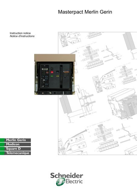
Masterpact Merlin Gerin
Masterpact Merlin Gerin
Masterpact Merlin Gerin

You also want an ePaper? Increase the reach of your titles
YUMPU automatically turns print PDFs into web optimized ePapers that Google loves.
T<br />
R<br />
t<br />
F<br />
I<br />
i<br />
T<br />
R<br />
t<br />
F<br />
I<br />
i<br />
T<br />
R<br />
<strong>Masterpact</strong> <strong>Merlin</strong> <strong>Gerin</strong><br />
Instruction notice<br />
Notice d'instructions<br />
pu<br />
90%<br />
I1 I2 I3<br />
50%<br />
20%<br />
STR 58 U<br />
Io Ir tr<br />
In = 2000A<br />
xIn xIo at 1.5Ir<br />
Im tm<br />
xIo<br />
Im<br />
3<br />
2<br />
4 5<br />
6<br />
8<br />
1.5 10<br />
15<br />
tm<br />
.3<br />
.2<br />
.4 .3<br />
.2<br />
.1<br />
.1 0<br />
I<br />
I<br />
Im = 5 x Ir<br />
(H2) 2<br />
max<br />
(H1) 2<br />
off<br />
I<br />
5Ir<br />
th<br />
In<br />
Ic2<br />
xIr xIr<br />
0A<br />
I<br />
Io<br />
0.63 0.8<br />
0.5 1<br />
8 12<br />
6 17<br />
4 22<br />
2 off<br />
Ir<br />
.9 .92<br />
.88 .95<br />
.85 .98<br />
.8 1<br />
I<br />
2<br />
tr<br />
Im 4 5<br />
tm<br />
Im<br />
test<br />
test<br />
4 5<br />
3 6<br />
2 8<br />
1.5 10<br />
xIn<br />
Ih th<br />
xIn<br />
Ic1 Ic2<br />
xIr xIr<br />
120 240<br />
60<br />
30 480<br />
15<br />
15<br />
tm<br />
.3<br />
.2<br />
Max.<br />
.4 .3<br />
.2<br />
.1<br />
.1 0<br />
I<br />
6<br />
4<br />
8 12<br />
17<br />
22<br />
2 off<br />
ex. : In = 2000A ; Ir = 1440A ; Im = 7200A<br />
In<br />
2000A<br />
Io 0.5 0.63 0.8 1<br />
préréglage : 1600A<br />
Ir 0.8 0.85 0.88 0.90 0.92 0.95 0.98 1<br />
Ir = 0.72 x In = 1440A<br />
Im 1.5 2 3 4 5 6 8 10<br />
I<br />
2<br />
Max.<br />
Im = 5 x Ir = 7200A<br />
(H2) 2<br />
max<br />
(H1) 2<br />
off<br />
push to reset<br />
90%<br />
50%<br />
20%<br />
I1 I2 I3<br />
Io Ir tr<br />
STR 58 U<br />
In = 2000A<br />
xIn xIo at 1.5Ir<br />
Im tm<br />
xIo<br />
Io<br />
0.63 0.8<br />
0.5 1<br />
Ir<br />
.9 .92<br />
.88 .95<br />
.85 .98<br />
.8 1<br />
I<br />
tr<br />
Im 4 5<br />
tm<br />
Im<br />
3<br />
2<br />
4 5<br />
6<br />
8<br />
1.5 10<br />
120 240<br />
60<br />
30 480<br />
15<br />
15<br />
tm<br />
.3<br />
.2<br />
.4 .3<br />
.2<br />
.1<br />
.1 0<br />
Ir<br />
Im<br />
0,4…1 In<br />
I<br />
1,5…10 Ir<br />
2…max<br />
2…off<br />
ex. : In = 2000A ; Ir = 1440A ; Im = 7200A<br />
In<br />
2000A<br />
Io 0.5 0.63 0.8 1<br />
préréglage : 1600A<br />
0.8 0.850.880.900.920.950.981<br />
Ir Ir = 0.72 x In = 1440A<br />
Im 1.5 2 3 4 5 6 8 10<br />
I<br />
Im = 5 x Ir = 7200A<br />
(H2) 2<br />
max<br />
(H1)<br />
2<br />
off<br />
I<br />
xIn<br />
Ih th<br />
xIn<br />
Ic1 Ic2<br />
test<br />
xIr xIr<br />
8 12<br />
6 17<br />
4 22<br />
2 off<br />
2<br />
Max.<br />
test<br />
26 mm<br />
%<br />
I2 I3<br />
Io Ir tr<br />
STR 58 U<br />
In = 2000A<br />
xIn xIo at 1.5Ir<br />
Im tm<br />
xIo<br />
Io<br />
0.63 0.8<br />
0.5 1<br />
Ir<br />
.9 .92<br />
.88 .95<br />
.85 .98<br />
.8 1<br />
I<br />
tr<br />
Im 4 5<br />
tm<br />
Im<br />
4 5<br />
3 6<br />
2 8<br />
1.5 10<br />
120 240<br />
60<br />
30 480<br />
15<br />
15<br />
tm<br />
.3<br />
.2<br />
.4 .3<br />
.2<br />
.1<br />
.1 0<br />
ex. : In = 2000A ; Ir = 1440A ; Im = 7200A<br />
In<br />
2000A<br />
Io 0.5 0.63 0.8 1<br />
préréglage : 1600A<br />
Ir 0.8 0.850.880.900.920.95 0.98 1<br />
Ir = 0.72 x In = 1440A<br />
Im 1.5 2 3 4 5 6 8 10<br />
I<br />
Im = 5 x Ir = 7200A<br />
(H2) 2<br />
max<br />
(H1) 2<br />
off<br />
Ir<br />
Im<br />
0,4…1 In<br />
I<br />
1,5…10 Ir
<strong>Merlin</strong> <strong>Gerin</strong> 1
contents<br />
identifying your <strong>Masterpact</strong><br />
discovering <strong>Masterpact</strong><br />
keep the qualities of <strong>Masterpact</strong> when not installed<br />
installing <strong>Masterpact</strong> in your switchboard<br />
c unpacking ......................................................................................................... 16<br />
c handling ............................................................................................................ 17<br />
c storing ............................................................................................................... 21<br />
c transport and handling in switch-board............................................................. 22<br />
c fixing in cubicle and connecting to main circuits ............................................... 24<br />
c fast frontal connection of auxiliaries, accessories, control unit ......................... 26<br />
c wiring diagrams ................................................................................................ 28<br />
c terminals attribution for auxiliaries and control unit .......................................... 38<br />
c operating diagrams for the different switches ................................................... 39<br />
preparing <strong>Masterpact</strong> to protect your network<br />
c drawout <strong>Masterpact</strong> : increased safety and continuity of service ..................... 42<br />
c carry out all the operating cycles ...................................................................... 48<br />
c lockings : mastered handling and operations ................................................... 50<br />
c accessories: complements to your <strong>Masterpact</strong> ................................................ 58<br />
c check <strong>Masterpact</strong> installation ........................................................................... 78<br />
c energize the main circuits ................................................................................. 78<br />
ensure the efficient protection and management of your network<br />
now <strong>Masterpact</strong> protects your network<br />
c identify your control unit .................................................................................... 80<br />
c STR 18 M : adjust your network protection ...................................................... 82<br />
c STR 28 D : adjust your network protection ....................................................... 84<br />
c STR 38 S : adjust the protection and manage your network ............................ 86<br />
c STR 58 U : adjust the protection and manage your network ............................ 88<br />
c STR 68 U : programme protection, management and analysis of your network 96<br />
c technical annex ................................................................................................. 124<br />
c tripping curves .................................................................................................. 128<br />
maintain the performances of <strong>Masterpact</strong><br />
troubles ?<br />
2 <strong>Merlin</strong> <strong>Gerin</strong>
sommaire<br />
identifiez votre <strong>Masterpact</strong><br />
découvrez <strong>Masterpact</strong><br />
préservez les qualités de <strong>Masterpact</strong> hors installation<br />
installez <strong>Masterpact</strong> dans votre tableau<br />
préparez <strong>Masterpact</strong> à protéger votre réseau<br />
assurez la protection et la gestion efficaces de votre réseau<br />
maintenant <strong>Masterpact</strong> protège votre réseau<br />
c déballage .......................................................................................................... 16<br />
c manutention ...................................................................................................... 17<br />
c stockage ........................................................................................................... 21<br />
c transport et manutention en tableaux ............................................................... 22<br />
c fixation en cellule et raccordement aux circuits principaux............................... 24<br />
c raccordement rapide en face avant des auxiliaires, accessoires,<br />
unité de contrôle ............................................................................................... 26<br />
c schémas électriques ......................................................................................... 28<br />
c affectation des bornes de raccordement des auxiliaires et<br />
de l'unité de contrôle ........................................................................................ 38<br />
c schémas de fonctionnement des différents contacts........................................ 39<br />
c masterpact débrochable : sécurité accrue et continuité de service .................. 42<br />
c réalisez tous les cycles de fonctionnement ...................................................... 48<br />
c les verrouillages : manipulations et fonctionnements ....................................... 50<br />
c les accessoires : compléments de votre <strong>Masterpact</strong> ........................................ 58<br />
c vérifiez l'installation de <strong>Masterpact</strong> ................................................................... 78<br />
c mettez sous tension les circuits principaux ...................................................... 78<br />
c identifiez votre unité de contrôle ....................................................................... 80<br />
c STR 18 M : réglez la protection de votre réseau .............................................. 82<br />
c STR 28 D : réglez la protection de votre réseau .............................................. 84<br />
c STR 38 S : réglez la protection et gérez votre réseau...................................... 86<br />
c STR 58 U : réglez la protection et gérez votre réseau ..................................... 88<br />
c STR 68 U : programmez la protection, la gestion et l'analyse de votre réseau 96<br />
c annexe technique ............................................................................................. 124<br />
c courbes de déclenchement .............................................................................. 128<br />
maintenez les performances de <strong>Masterpact</strong><br />
vous avez un problème ?<br />
<strong>Merlin</strong> <strong>Gerin</strong> 3
4 <strong>Merlin</strong> <strong>Gerin</strong>
identifying your <strong>Masterpact</strong><br />
identifiez votre <strong>Masterpact</strong><br />
face plate<br />
plaque de firme<br />
E32264<br />
rated insulation voltage<br />
tension d'isolement<br />
breaking capacity<br />
pouvoir de coupure<br />
short time withstand<br />
tenue thermique<br />
MERLIN GERIN<br />
masterpact<br />
M25 H2<br />
Ui 1000V ~ 50/60Hz<br />
Ue 380/440V 480/690V<br />
Icu 100kA 85kA<br />
Ics 100kA 85kA<br />
Icw 75kA 1s<br />
IEC 947-2<br />
type of breaker<br />
type de l'appareil<br />
rated frequency<br />
fréquence d'utilisation<br />
rated operational voltage<br />
tension d'emploi<br />
<strong>Merlin</strong> <strong>Gerin</strong> 5
identifying your <strong>Masterpact</strong><br />
identifiez votre <strong>Masterpact</strong><br />
circuit breaker and chassis<br />
appareil et chassis<br />
E50830<br />
performance<br />
performance<br />
number of poles<br />
nombre de pôles<br />
order<br />
n° de commande<br />
order item<br />
n° de poste<br />
date of<br />
manufacture<br />
date<br />
de fabrication<br />
drawout (D)<br />
or fixed (F)<br />
débrochable (D)<br />
ou fixe (F)<br />
serie<br />
standard (S)<br />
special (Z)<br />
standard (S)<br />
special (Z)<br />
IN<br />
x<br />
lower<br />
connection<br />
raccordement<br />
inférieur<br />
size<br />
taille<br />
control unit<br />
unité de contrôle<br />
CT rating<br />
calibre des TC<br />
neutral CT rating<br />
calibre du TC neutre<br />
neutral position<br />
position du neutre<br />
G : left / gauche<br />
D : right / droit<br />
upper connection<br />
raccordement<br />
supérieur<br />
auxiliaries and options<br />
auxiliaires et options<br />
E50831<br />
wiring diagram<br />
n° de schéma électrique<br />
closing contacts<br />
contacts à fermeture<br />
geared motor<br />
moto-réducteur<br />
auxiliary contacts<br />
contacts auxiliaires<br />
opening contacts<br />
contacts à ouverture<br />
closing release<br />
electro de fermeture<br />
shunt release<br />
déclench. à émission<br />
de courant<br />
undervoltage release<br />
déclench. à minimum<br />
de tension<br />
DIAGRAM 685 353<br />
MCH 200/240 AC<br />
XF 200/220 DC - 200/250 AC<br />
MX1 200/220 DC - 200/250 AC<br />
MX2<br />
MN<br />
MNR<br />
STU<br />
F<br />
O<br />
SDE<br />
OF<br />
T2<br />
F<br />
2 10A/240V AC<br />
2 10A/240V AC<br />
1 10A/240V AC<br />
4 10A/240V AC<br />
time delayed undervoltage<br />
release<br />
déclencheur à minimum<br />
de tension retardée<br />
control unit<br />
supply voltage<br />
tension d'alimentation<br />
de l'unité de contrôle<br />
control unit<br />
options<br />
options de l'unité<br />
de contrôle<br />
fault trip indicator<br />
signal de déclenchement<br />
sur défaut<br />
control unit (see page 80)<br />
unité de contrôle (voir page 80)<br />
6 <strong>Merlin</strong> <strong>Gerin</strong>
F<br />
t<br />
90<br />
%Ir<br />
105<br />
90%<br />
50%<br />
20%<br />
.9 .92 120 240<br />
0.63 0.8<br />
. 8 .95 60<br />
0.5 1<br />
.85 .98 30 480<br />
.8 1 15<br />
at 1,5Ir<br />
4 5 .4 .3<br />
3 6 .3 .2<br />
2 8 .2 .1<br />
1.5 10 .1 0<br />
on I 2 t o f<br />
8 12<br />
6 17<br />
Ir fault<br />
4<br />
2<br />
2 o f<br />
tr<br />
Ih<br />
5 0 6 0 .4 .4<br />
fault Im fault<br />
4 0<br />
8 0 .3 .3<br />
tm<br />
th<br />
320<br />
1 0 .2 .2<br />
I<br />
250 12 0 .1 .1<br />
on I 2 t o f<br />
.9 .93 .8 .85<br />
.86 .95 .7 .9<br />
.85 .98 .6 .95<br />
.8 1<br />
.5 1<br />
xIr<br />
xIr<br />
test<br />
test<br />
xIn<br />
+ S –<br />
– T +<br />
Ir :<br />
Im :<br />
th :<br />
i<br />
I<br />
A<br />
xIn<br />
xIo<br />
xIo<br />
reset V<br />
tr<br />
I<br />
IG LI<br />
I<br />
LIG<br />
LG G<br />
L o f<br />
R<br />
T<br />
Ui<br />
Ue<br />
Icu<br />
Ics<br />
Icw<br />
F<br />
t<br />
90%<br />
50%<br />
20%<br />
.9 .92 120 240<br />
0.63 0.8<br />
. 8 .95 60<br />
0.5 1<br />
.85 .98 30 480<br />
.8 1 15<br />
at 1,5Ir<br />
4 5 .4 .3<br />
3 6 .3 .2<br />
2 8 .2 .1<br />
1.5 10 .1 0<br />
on I 2 t o f<br />
8 12<br />
6 17<br />
Ir fault<br />
4<br />
2<br />
2 o f<br />
tr<br />
Ih<br />
5 0 6 0 .4 .4<br />
fault Im fault<br />
4 0<br />
8 0 .3 .3<br />
tm<br />
th<br />
320<br />
1 0 .2 .2<br />
I<br />
250 12 0 .1 .1<br />
on I 2 t o f<br />
.9 .93 .8 .85<br />
.86 .95 .7 .9<br />
.85 .98 .6 .95<br />
.8 1<br />
.5 1<br />
xIr<br />
xIr<br />
90<br />
%Ir<br />
105<br />
test<br />
test<br />
xIn<br />
+ S –<br />
– T +<br />
Ir :<br />
Im :<br />
th :<br />
i<br />
I<br />
A<br />
xIn<br />
xIo<br />
xIo<br />
reset V<br />
tr<br />
I<br />
IG LI<br />
I<br />
LIG<br />
LG G<br />
L o f<br />
R<br />
T<br />
Ui<br />
Ue<br />
Icu<br />
Ics<br />
Icw<br />
F<br />
t<br />
90<br />
%Ir<br />
105<br />
Ih<br />
fault<br />
90%<br />
50%<br />
20%<br />
th<br />
Io Ir<br />
0.63<br />
Ir fault<br />
tr<br />
test<br />
test<br />
0.5 1<br />
xIn<br />
Ir :<br />
Im :<br />
th :<br />
Im fault<br />
tm<br />
I<br />
+ S –<br />
– T +<br />
0.8<br />
i<br />
I<br />
reset V<br />
.9 .92 120 240<br />
. 8 .95 60<br />
.85 .98 30 480<br />
.8 1 15<br />
at 1,5Ir<br />
4 5 .4 .3<br />
3 6 .3 .2<br />
2 8 .2 .1<br />
1.5 10 .1 0<br />
on I 2 t o f<br />
xIo<br />
Im tm<br />
4<br />
6<br />
2<br />
xIo<br />
8 12<br />
17<br />
xIn<br />
Ih th<br />
5 0 6 0 .4 .4<br />
4 0<br />
8 0 .3 .3<br />
320<br />
1 0 .2 .2<br />
250 12 0 .1 .1<br />
on I 2 t o f<br />
.9 .93 .8 .85<br />
.86 .95 .7 .9<br />
.85 .98 .6 .95<br />
.8 1<br />
.5 1<br />
xIr<br />
xIr<br />
A<br />
o f<br />
2<br />
tr<br />
Ic1 Ic2<br />
IG LI<br />
I<br />
LIG<br />
LG G<br />
L o f<br />
I<br />
T<br />
R<br />
Ui<br />
Ue<br />
Icu<br />
Ics<br />
Icw<br />
85kA<br />
85kA<br />
E43374<br />
push to reset<br />
I1 I2 I3<br />
STR 58 UE<br />
Io Ir<br />
Im tm<br />
Ih th<br />
Ic1 Ic2<br />
O<br />
I<br />
push OFF<br />
push ON<br />
O OFF discharged<br />
00000<br />
MERLIN GERIN<br />
masterpact<br />
M32 H1<br />
1000V<br />
380/440V<br />
100kA<br />
100kA<br />
75kA 1s<br />
50/60Hz<br />
480/690V<br />
85kA<br />
85kA<br />
IEC 947-2<br />
E32696<br />
push to reset<br />
connected<br />
test<br />
disconnected<br />
I1 I2 I3<br />
STR 58 UE<br />
O<br />
push OFF<br />
I<br />
push ON<br />
MERLIN GERIN<br />
masterpact<br />
M32 H1<br />
1000V<br />
380/440V<br />
100kA<br />
100kA<br />
50/60Hz<br />
480/690V<br />
O OFF discharged<br />
00000<br />
75kA 1s<br />
IEC 947-2<br />
E43375<br />
push to reset<br />
I1 I2 I3<br />
STR 58 UE<br />
Io Ir<br />
Im tm<br />
O<br />
I<br />
push OFF<br />
push ON<br />
O OFF discharged<br />
MERLIN GERIN<br />
masterpact<br />
M32 H1<br />
1000V<br />
380/440V<br />
100kA<br />
100kA<br />
75kA 1s<br />
50/60Hz<br />
480/690V<br />
85kA<br />
85kA<br />
IEC 947-2<br />
00000<br />
Ih th<br />
Ic1 Ic2<br />
connected<br />
test<br />
disconnected<br />
<strong>Merlin</strong> <strong>Gerin</strong> 7
8 <strong>Merlin</strong> <strong>Gerin</strong>
discovering <strong>Masterpact</strong>…<br />
découvrez <strong>Masterpact</strong>…<br />
E32265<br />
<strong>Merlin</strong> <strong>Gerin</strong><br />
9<br />
10
chassis<br />
châssis<br />
circuit-breaker<br />
disjoncteur<br />
E32266<br />
arc chute cover<br />
capot sur chambres<br />
de coupure<br />
handling handgrip<br />
poignée de manutention<br />
terminal shield<br />
capot bornier<br />
4 connected position<br />
carriage switches<br />
4 contacts de position<br />
"embroché"<br />
E32267<br />
shunt release<br />
déclencheur à<br />
émission de courant<br />
arc chute cover<br />
(for fixed version)<br />
capot sur chambres<br />
de coupure<br />
(pour version fixe)<br />
undervoltage, release or second shunt release<br />
déclencheur à minimum de tension ou<br />
2 ème déclencheur à émission de courant<br />
closing release<br />
électro-aimant de fermeture<br />
safety shutters<br />
volets isolants<br />
"open" position key lock<br />
serrure de verrouillage en<br />
position "ouvert"<br />
4 auxiliary switches<br />
4 contacts auxiliaires<br />
ouvert/fermé<br />
2 "disconnected" position<br />
carriage switches<br />
2 contacts de position<br />
"débroché"<br />
auxiliaries and control unit<br />
connection block<br />
borniers raccordement<br />
des auxiliaires et de<br />
l'unité de contrôle<br />
door interlock<br />
verrouillage de porte<br />
padlockable slide<br />
sabot de verrouillage<br />
des volets<br />
racking interlock<br />
verrouillage<br />
embrochage débrochage<br />
porte ouverte<br />
padlocking facilities for<br />
"connected" or "disconnected"<br />
position<br />
verrouillage par cadenas<br />
en position "embroché"<br />
ou "débroché"<br />
arc chute<br />
chambre de coupure<br />
2 opening contacts<br />
2 closing contacts<br />
2 contacts à ouverture<br />
2 contacts à fermeture<br />
handling handgrip<br />
poignée de<br />
manutention<br />
ready-to-close contact<br />
contact prêt à fermer<br />
stored energy mechanism<br />
charging handle<br />
poignée d'armement<br />
de la commande<br />
operations counter<br />
compteur de manoeuvres<br />
motor for electrical<br />
charging of stored<br />
energy mechanism<br />
moto-réducteur pour<br />
commande électrique<br />
pull-out handgrip<br />
poignée d'extraction<br />
fixing braket<br />
(for fixed version)<br />
équerres latérales<br />
(pour installation en fixe)<br />
racking handle storage<br />
rangement de la manivelle<br />
keylocks for "connected"<br />
or "disconnected" positions<br />
verrouillage par serrure en position<br />
"embroché" ou "débroché"<br />
control unit<br />
unité de contrôle<br />
closing push-button<br />
bouton poussoir de fermeture<br />
racking handle<br />
manivelle d'embrochage<br />
functional position indicator "connected",<br />
"test" and "disconnected"<br />
témoin de position fonctionnelle "embroché",<br />
"test" et "débroché"<br />
supports<br />
supports de l'appareil<br />
opening push-button<br />
bouton poussoir d'ouverture<br />
sealing plate<br />
plaque de plombage<br />
11 12<br />
<strong>Merlin</strong> <strong>Gerin</strong>
discovering <strong>Masterpact</strong>…<br />
découvrez <strong>Masterpact</strong>…<br />
front cover<br />
face avant<br />
E32268<br />
face plate<br />
(see page 5)<br />
plaque de firme<br />
(voir page 5)<br />
push-button locking device<br />
cadenassage ou plombage<br />
des boutons poussoirs<br />
main contact position indicator<br />
témoin de position des contacts principaux<br />
energy storing mechanism status indicator<br />
témoin d'armement de la commande<br />
<strong>Merlin</strong> <strong>Gerin</strong> 13
14 <strong>Merlin</strong> <strong>Gerin</strong>
keep the qualities of <strong>Masterpact</strong> when not installed<br />
préservez les qualités de <strong>Masterpact</strong> hors installation<br />
<strong>Merlin</strong> <strong>Gerin</strong> 15
unpacking<br />
déballage<br />
We advise when unpacking to check that breakers don't present any prejudicial damage to a good working.<br />
Otherwise send reservations to the transporter by means of a registered letter.<br />
Nous conseillons lors du déballage de s'assurer que les appareils n'ont pas subi de choc nuisible à leur bon fonctionnement.<br />
Le cas échéant, adresser les réserves d'usage, sous pli recommandé, au transporteur.<br />
fixed breaker<br />
appareil fixe<br />
complete drawout breaker<br />
appareil débrochable complet<br />
E32269<br />
E32270<br />
E32271<br />
connected<br />
disconnected<br />
disconnect the breaker (see page 46)<br />
débrochez le disjoncteur (voir page 46)<br />
extract the breaker (see page 47)<br />
extraire le disjoncteur (voir page 47)<br />
drawout breaker alone<br />
appareil débrochable seul<br />
E32272<br />
A<br />
E32273<br />
E32274<br />
≤ 4000A x 3<br />
remove the 2 fixing parts<br />
otez les 2 plaques de fixation<br />
put another wooden battledore and turn back the<br />
breaker (never on the front cover)<br />
mettez une 2ème palette et retournez l'appareil vers<br />
l'arrière (jamais sur sa face avant)<br />
chassis alone with or without shutters<br />
châssis seul avec ou sans volets<br />
E30011<br />
E32275<br />
B<br />
2<br />
1 2<br />
1<br />
➀<br />
unscrew the 4 fixing screws<br />
dévisser les 4 vis de fixations<br />
then proceed as mentionned<br />
on drawing A or B<br />
puis procédez comme décrit sur le dessin A ou B ≥ 4000A x 4<br />
➁<br />
put another wooden battledore, turn front<br />
the breaker and remove the plastic ties<br />
mettez une 2 ème palette, retournez l'appareil<br />
vers l'avant et retirez les frettes<br />
16 <strong>Merlin</strong> <strong>Gerin</strong>
handling<br />
manutention<br />
■ ≤ 4000A x 3<br />
table of weights in kg (max)<br />
tableau des masses en kg (maxi)<br />
rating 800 - 1250 N/H/L 1600 N/H 2000 - 2500 N/H 3200 H 4000 H<br />
calibre 1600 L 2000 - 2500 L<br />
nr of Poles 3 4 3 4 3 4 3 4 3<br />
nb de Pôles<br />
circuit breaker 43 54 46 58 55 69 80 90 76<br />
appareil<br />
chassis 22 26 23 27 27 33 50 60 76<br />
châssis<br />
E32276<br />
E32277<br />
chassis or circuit breaker : 2 of you to lift it<br />
châssis ou appareil : soulevez -le à 2<br />
before handling, remove the<br />
circuit breaker from its chassis<br />
(see page 46)<br />
avant toute manutention sortir<br />
l'appareil de son châssis<br />
(voir page 46)<br />
E32278<br />
breaker<br />
appareil<br />
E32279<br />
sling Ø10 maxi<br />
élingue Ø10 maxi<br />
E32280<br />
<strong>Merlin</strong> <strong>Gerin</strong> 17
handling<br />
manutention<br />
E32281<br />
chassis alone without arc chute cover<br />
châssis seul sans capot sur chambre<br />
sling<br />
élingue<br />
E32283<br />
E32282<br />
E32284<br />
chassis alone with arc chute cover<br />
châssis seul avec capot sur chambre<br />
sling Ø 10 maxi<br />
élingue Ø 10 maxi<br />
E32286<br />
E32285<br />
■ ≥ 4000A x 4<br />
table of weights in kg (maxi)<br />
tableau des masses en kg (maxi)<br />
rating 4000 H 5000 H 6300 H<br />
calibre<br />
nr of Poles 4 3 4 3 4<br />
nb de Pôles<br />
circuit breaker 90 95 100 105 115<br />
appareil<br />
chassis 110 120 130 140 150<br />
châssis<br />
Take care :<br />
handle breaker and chassis ≥ 4000A x 4 separately<br />
Attention :<br />
manutentionner séparément les appareils et les châssis ≥ 4000A x 4<br />
18 <strong>Merlin</strong> <strong>Gerin</strong>
E32287<br />
breaker<br />
appareil<br />
E32288<br />
Risk to damage the chassis escutcheon if<br />
the forks stick out.<br />
Risque de détérioration<br />
du plastron de châssis<br />
si les fourches dépassent.<br />
E32289<br />
E32292<br />
with lifter (see page 77)<br />
avec chariot élévateur (voir page 77)<br />
with special hooks (*) and compensation bar<br />
avec crochets spéciaux (*) et palonnier<br />
slings Ø 10 maxi<br />
élingues Ø 10 maxi<br />
with special hooks(*)<br />
avec crochets spéciaux(*)<br />
<br />
E32290<br />
E32293<br />
with slings and compensation bar<br />
avec élingues et palonnier<br />
with slings<br />
avec élingues<br />
<strong>Merlin</strong> <strong>Gerin</strong> 19<br />
E32291<br />
E32294<br />
800 mm<br />
mini
E32295<br />
E32297<br />
E32282<br />
E32302<br />
handling<br />
manutention<br />
chassis alone<br />
châssis seul<br />
with lifter (see page 77)<br />
avec chariot élévateur (see page 77)<br />
chassis alone without arc chute cover<br />
châssis seul sans capot sur chambre<br />
with special hooks (*) and compensation bar<br />
avec crochets spéciaux (*) et palonnier<br />
sling<br />
élingue<br />
chassis alone with arc chute cover<br />
châssis seul avec capot sur chambre<br />
with special hooks (*) and compensation bar<br />
avec crochets spéciaux (*) et palonnier<br />
E32296<br />
with special hooks (*) and slings<br />
avec crochets spéciaux (*) et élingues<br />
with slings and compensation bar<br />
avec élingues et palonnier<br />
with slings<br />
avec élingues<br />
20 <strong>Merlin</strong> <strong>Gerin</strong><br />
30<br />
To avoid the chassis to capsize,<br />
put a 50 x 30 mm chock.<br />
Remove it as soon as the ends of forks<br />
lean on the cubicle floor.<br />
Pour éviter le renversement du châssis,<br />
mettre un chevron de 50 x 30 mm.<br />
Le retirer dès que les bouts des fourches<br />
50<br />
sont en appui dans la cellule.<br />
<br />
E32298<br />
E32300<br />
E32303<br />
800 mm<br />
mini<br />
E32299<br />
E32301<br />
E32304<br />
800 mm<br />
mini<br />
with slings and compensation bar<br />
avec élingues et palonnier
E32285<br />
sling Ø 10 maxi<br />
élingue Ø 10 maxi<br />
E32305<br />
800 mm<br />
mini<br />
E32306<br />
800 mm<br />
mini<br />
with special hooks (*) and slings<br />
avec crochets spéciaux (*) et élingues<br />
with slings<br />
avec élingues<br />
(*) these special hooks can be provided in option - see page 77<br />
(*) ces crochets spéciaux peuvent être fournis en option - voir page 77<br />
storing<br />
stockage<br />
E32307<br />
notice<br />
masterpact<br />
cover<br />
house<br />
E32308<br />
maximum permitted<br />
maximum autorisé<br />
≤ 3200A<br />
≥ 4000A<br />
E32310<br />
E32309<br />
notice<br />
masterpact<br />
cover<br />
house<br />
do not store breaker uncovered<br />
ne pas stocker un appareil sans housse<br />
E50852<br />
100°C max.<br />
It is not recommended to<br />
store the breakers in<br />
corrosive or salt- laden<br />
environment<br />
Il est déconseillé<br />
de stocker les appareils<br />
dans une atmosphère<br />
corrosive ou saline<br />
E508531<br />
E32311<br />
–50°C min.<br />
open<br />
ouvert<br />
discharged<br />
désarmé<br />
<strong>Merlin</strong> <strong>Gerin</strong> 21
transport and handling in switch-board<br />
transport et manutention en tableaux<br />
■ ≤ 4000A x 3<br />
breaker in chassis<br />
appareil dans châssis<br />
E32312<br />
connected<br />
test<br />
disconnected<br />
chassis alone with or without shutters<br />
châssis seul avec ou sans volets<br />
E32313<br />
fixe the clusters with hoops<br />
fixer les pinces avec des frettes<br />
■ ≥ 4000A x 4<br />
chassis alone with or without shutters only<br />
châssis seul avec ou sans volets uniquement<br />
E32313<br />
fixe the clusters with hoops<br />
fixer les pinces avec des frettes<br />
22 <strong>Merlin</strong> <strong>Gerin</strong>
installing your <strong>Masterpact</strong> in your switchboard<br />
installez <strong>Masterpact</strong> dans votre tableau<br />
<strong>Merlin</strong> <strong>Gerin</strong> 23
fixing in cubicle and connecting to main circuits<br />
fixation en cellule et raccordement aux circuits principaux<br />
Use the installation and connection drawing provided with the breaker<br />
Utilisez le plan d'installation et de raccordement fourni avec l'appareil<br />
For fixing, use M10 bolts, class 8.8.<br />
For connection, use H M10 screws with contact washer and nut, class 8.8.<br />
Pour toute fixation, utilisez des boulons M10, classe 8,8.<br />
Pour tout raccordement, utilisez des vis H M10 avec rondelle contact et écrou classe 8,8.<br />
tightening torque : 50 mN<br />
couple de serrage : 50 mN<br />
fixed breaker ≤ 3200A<br />
appareil fixe ≤ 3200A<br />
position <strong>Masterpact</strong> in<br />
the switchboard<br />
positionnez <strong>Masterpact</strong> dans<br />
le tableau<br />
E32314<br />
E32315<br />
E32316<br />
fix<br />
fixez<br />
connect<br />
raccordez<br />
fixed breaker with front connector ≤ 3200A<br />
appareil fixe avec prise avant ≤ 3200A<br />
E32317<br />
E32318<br />
E32319<br />
E32320<br />
1<br />
4<br />
2 3<br />
on the edge of a table or in the<br />
cubicle<br />
en bord de table ou dans le tableau<br />
assemble 1-2-3-4<br />
montez 1-2-3-4<br />
position and fix the breaker, slide<br />
the screen<br />
positionnez et fixez l'appareil,<br />
glissez l'écran<br />
connect<br />
raccordez<br />
fixed breaker 4000A et 5000A tri<br />
appareil fixe 4000A et 5000A tri<br />
position the breaker in<br />
the switchboard<br />
positionnez l'appareil dans le<br />
tableau<br />
E32321<br />
E32322<br />
E32323<br />
fix<br />
fixez<br />
connect<br />
raccordez<br />
24 <strong>Merlin</strong> <strong>Gerin</strong>
drawout breaker ≤ 4000A x 3<br />
appareil débrochable ≤ 4000A x 3<br />
position the chassis in the<br />
switchboard<br />
positionnez le châssis dans le<br />
tableau<br />
E32324<br />
E32325<br />
E32326<br />
drawout breaker ≥ 4000A x 4<br />
appareil débrochable ≥ 4000A x 4<br />
position the chassis in the<br />
switchboard<br />
positionnez le châssis dans le<br />
tableau<br />
E32327<br />
fix<br />
fixez<br />
E32328<br />
connect<br />
raccordez<br />
E32329<br />
fix<br />
fixez<br />
X6<br />
connect<br />
raccordez<br />
drawout breaker with front connector up to 2500A<br />
appareil débrochable avec prise avant jusqu'à 2500A<br />
position the chassis in the<br />
switchboard<br />
positionnez le châssis dans le<br />
tableau<br />
E32324<br />
E32330<br />
A<br />
E32331<br />
fix<br />
fixez<br />
adapt the screen<br />
adaptez l'écran<br />
connect<br />
raccordez<br />
3200A drawout breaker with front connector<br />
appareil débrochable 3200A avec prise avant<br />
E32332<br />
E32333<br />
E32324<br />
E32334<br />
1<br />
2<br />
on the edge of table, assemble 1-2-3-4<br />
en bord de table, montez 1-2-3-4<br />
3<br />
4<br />
fix 4 (M6 screws)<br />
torque : 13 m.N class 8.8<br />
fixez 4 (vis M6)<br />
couple : 13 mN classe 8,8<br />
adapt the screen (see A) then position<br />
and fix the chassis<br />
adaptez l'écran (voir A) puis positionnez<br />
et fixez le châssis<br />
connect<br />
raccordez<br />
Earthing connection of the chassis : 2 holes Ø 10 mm, on each side of the chassis, located by :<br />
Raccordement de mise à la terre du châssis : 2 trous Ø 10 mm de chaque côté du châssis repérés par :<br />
<strong>Merlin</strong> <strong>Gerin</strong> 25
fast frontal connection of auxiliaries, accessories, control unit<br />
raccordement rapide en face avant des auxiliaires, accessoires, unité de contrôle<br />
fixed breaker<br />
appareil fixe<br />
E32335<br />
E32336<br />
2<br />
E32338<br />
1 1<br />
E32337<br />
fixed connector<br />
prise de raccordement<br />
connect<br />
connectez<br />
1 press - 2 push down<br />
1 appuyez - 2 enfoncez<br />
E32339<br />
44<br />
41<br />
42<br />
34<br />
31<br />
32<br />
24<br />
21<br />
22<br />
14<br />
11<br />
12<br />
262 B4 B1<br />
D4 D1 254<br />
A4 A1 251<br />
C2 C1 252<br />
E30050<br />
cross-section of wires<br />
section des fils<br />
min. S : 0,6 mm 2<br />
max. S : 2,5 mm 2<br />
9 mm<br />
determine the terminals of the part to<br />
be connected<br />
déterminez les bornes de l'élément<br />
à connecter<br />
locate them<br />
repérez-les<br />
bare the wires<br />
dénudez les fils<br />
E32340<br />
E32341<br />
3<br />
1<br />
E32342<br />
E32343<br />
1<br />
2<br />
3<br />
2<br />
screwdriver Ø 4 max<br />
tournevis Ø 4 maxi<br />
refit the shield<br />
remettre le capot<br />
26 <strong>Merlin</strong> <strong>Gerin</strong>
drawout breaker<br />
appareil débrochable<br />
E32344<br />
E32345<br />
E32346<br />
B<br />
remove the terminal block shield<br />
enlevez le capot bornier<br />
locate them<br />
repérez-les<br />
Possibility to remove the front plate B (2 screws) to facilitate the connection<br />
Possibilité de retirer la traverse B (2 vis) pour faciliter le raccordement<br />
cross-section of wires<br />
section des fils<br />
E32347<br />
E32348<br />
E30050<br />
min. S : 0,6 mm 2<br />
3<br />
3<br />
max. S : 2,5 mm 2<br />
1<br />
1<br />
9 mm<br />
2<br />
2<br />
bare the wires<br />
dénuder les fils<br />
screwdriver Ø 4 max.<br />
tournevis Ø 4 maxi<br />
E32349<br />
E30053<br />
Do not run the wires over the arc chutes<br />
or near the leakage of the arc chute<br />
cover.<br />
Ne pas passer les fils au dessus des<br />
chambres de coupure, ou près des<br />
échappements du capot sur chambre.<br />
refit the shield<br />
remettre le capot<br />
wiring without shield<br />
câblage sans capot<br />
drawout breaker with fixed connectors (same as fixed breaker)<br />
appareil débrochable avec prises de raccordement (idem à l'appareil fixe)<br />
additional terminal block for extra connections, (see page 72)<br />
bornier supplémentaire pour raccordement multiple, (voir page 72)<br />
<strong>Merlin</strong> <strong>Gerin</strong> 27
wiring diagrams<br />
schémas électriques<br />
general diagram<br />
for basic version<br />
STR 08 to 58<br />
E30721<br />
CHÂSSIS AUXILIARIES<br />
CN 1 - CN +<br />
CONTROL UNIT<br />
BREAKER AUXILIARIES<br />
Fu (1)<br />
AT<br />
BPO<br />
ready<br />
to<br />
closed<br />
connected<br />
disconnected fault closed<br />
open<br />
BPF<br />
springs<br />
charged<br />
314 312 324 322 334 332 344 342 352 354 362 364 372 374<br />
82 84<br />
212 222<br />
234 244 12 14 22 24 32 34 42 44 D4 C12<br />
C2<br />
A4<br />
252 254 262 B4<br />
CE<br />
ou or<br />
MN<br />
or<br />
MNR<br />
MX<br />
XF<br />
M<br />
OF<br />
MX<br />
F<br />
F<br />
O<br />
O<br />
SDE<br />
CH<br />
processing<br />
unit<br />
PF<br />
CD<br />
CT<br />
311 321<br />
331 341<br />
351 361<br />
371<br />
81<br />
211 221<br />
231 241<br />
11 21 31<br />
41 D1<br />
C11<br />
C1<br />
A1<br />
251<br />
B1<br />
CN2 - CN –<br />
Fu (1)<br />
Fu : fuse<br />
AT : emergency off<br />
BPO : open pushbutton<br />
BPF : close pushbutton<br />
CE : "connected" position contact<br />
(10A/240V AC)<br />
M : spring charging motor (180VA)<br />
XF : closing release (20VA)<br />
MX : shunt release (20VA)<br />
MN : undervoltage release (20VA)<br />
MNR : time delayed undervoltage release<br />
(20VA)<br />
OF : auxiliary changeover contacts<br />
(10A/240V AC)<br />
O<br />
F<br />
SDE<br />
CH<br />
PF<br />
CD<br />
CT<br />
: 2 auxiliary NO contacts<br />
(10A/240V AC)<br />
: 2 auxiliary NC contacts<br />
(10A/240V AC)<br />
: fault trip indication contact<br />
(10A/240V AC)(exept STR 08)<br />
: "spring charged" contact<br />
(10A/240V AC)<br />
: ready to close contact<br />
(10A/240V AC) (closing possible if<br />
breaker is open, not locked and<br />
operating mechanism charged)<br />
: "disconnected" position contact<br />
(10A/240V AC)<br />
: "test" position contact<br />
(10A/240V AC)<br />
E30718<br />
MNR wiring for instantaneous tripping<br />
D4<br />
D1<br />
MNR<br />
254 262<br />
Use the terminal 262<br />
("spring charged contact")<br />
and 254 (normally open contact of the PF)<br />
(1) to determine according to the auxiliary<br />
consumptions.<br />
Accessories such as pushbuttons, lamps and fuses<br />
are not supplied with the circuit breaker<br />
Diagram shown with circuits de-energized, all<br />
devices open and relays in normal position, MN or<br />
MNR energized.<br />
source : 689 905<br />
28 <strong>Merlin</strong> <strong>Gerin</strong>
schéma général<br />
pour version de base<br />
STR 08 à 58<br />
E30721<br />
AUXILIAIRES CHÂSSIS UNITÉ DE CONTRÔLE AUXILIAIRES APPAREIL<br />
CN 1 - CN +<br />
Fu (1)<br />
AT<br />
BPO<br />
prêt à<br />
fermer<br />
embroché<br />
débroché défaut fermé<br />
ouvert<br />
BPF<br />
armé<br />
314 312 324 322 334 332 344 342 352 354 362 364 372 374<br />
82 84<br />
212 222<br />
234 244 12 14 22 24 32 34 42 44 D4 C12<br />
C2<br />
A4<br />
252 254 262 B4<br />
CE<br />
ou<br />
MN<br />
ou<br />
MNR<br />
MX<br />
XF<br />
M<br />
OF<br />
MX<br />
F<br />
F<br />
O<br />
O<br />
SDE<br />
CH<br />
unité de<br />
traitement<br />
PF<br />
CD<br />
CT<br />
311 321<br />
331 341<br />
351 361<br />
371<br />
81<br />
211 221<br />
231 241<br />
11 21 31<br />
41 D1<br />
C11<br />
C1<br />
A1<br />
251<br />
B1<br />
CN2 - CN –<br />
Fu (1)<br />
Fu : fusible de protection<br />
AT : arrêt d'urgence<br />
BPO : bouton poussoir ouverture<br />
BPF : bouton poussoir fermeture<br />
CE : contact position "embroché"<br />
(10A/240V CA)<br />
M : moteur réarmement (180VA)<br />
XF : électro de fermeture (20VA)<br />
MX : déclencheur à émission de courant<br />
(20VA)<br />
MN : déclencheur à minimum de tension<br />
(20VA)<br />
MNR : déclencheur à minimum de tension<br />
retardé (20VA)<br />
OF : contacts auxiliaires inverseurs<br />
(10A/240V CA)<br />
O<br />
F<br />
SDE<br />
CH<br />
PF<br />
CD<br />
CT<br />
: contacts auxiliaires normalement<br />
ouverts (10A/240V CA)<br />
: contacts auxiliaires normalement<br />
fermés (10A/240V CA)<br />
: contact défaut maxi d'intensité<br />
(10A/240V CA)(sauf STR 08)<br />
: contact "ressorts chargés"<br />
(10A/240V CA)<br />
: contact prêt à fermer (10A/240V CA)<br />
(fermeture possible si appareil<br />
ouvert, non verrouillé et cde. armée)<br />
: contact position "débroché"<br />
(10A/240V CA)<br />
: contact position "test"<br />
(10A/240V CA)<br />
E30718<br />
câblage MNR pour déclenchement instantané<br />
D4<br />
D1<br />
MNR<br />
254 262<br />
Utilise les bornes 262<br />
(signalisation "ressorts chargés")<br />
et 254 (contact à fermeture du PF)<br />
(1) a calculer en fonction des puissances des<br />
auxiliaires.<br />
Les accessoires tels que boutons poussoirs,<br />
coupe-circuits ne sont pas fournis avec le<br />
disjoncteur.<br />
Schéma représenté circuit "hors tension" appareil<br />
"ouvert, embroché, armé", relais en position<br />
"repos", MN ou MNR alimentée.<br />
source : 689 888<br />
<strong>Merlin</strong> <strong>Gerin</strong> 29
wiring diagrams<br />
schémas électriques<br />
STR 28 / STR 38 / STR 58<br />
■ ground fault protection (T/W)<br />
■ load monotoring (R)<br />
■ local indicator (F)<br />
■ ammeter (I)<br />
■ selected fault(s) trip indicator (FV)<br />
■ data transmission (C)<br />
■ overrun current contact alarm (ALR)<br />
FRAME AUXILIARIES CONTROL UNIT BREAKER AUXILIARIES<br />
CN 1 - CN +<br />
Fu (6)<br />
N<br />
P1<br />
P2<br />
S1<br />
S2<br />
314<br />
connected<br />
312<br />
324<br />
322<br />
334<br />
332<br />
344<br />
342<br />
352<br />
354<br />
(4)<br />
(4)<br />
BPF<br />
disconnected LR<br />
fault closed<br />
open<br />
spring<br />
(2) alarm<br />
Ic1 Ic2<br />
charged<br />
(5)<br />
Z11 Z12 LR2 T2 T1 V2 R1 R2 e + e – 82 84 212 222 234 244 12 14 22 24 32 34 42 44 D4 C12 C2 A4 252 254 262 B4<br />
362<br />
364<br />
372<br />
374<br />
AT<br />
BPO<br />
ready<br />
to<br />
close<br />
CE<br />
or<br />
T<br />
MN<br />
or<br />
MNR<br />
OF<br />
MX<br />
MX<br />
XF<br />
M<br />
F<br />
V<br />
SDE<br />
F<br />
F<br />
O<br />
O<br />
CH<br />
processing<br />
unit<br />
ALR<br />
ammeter<br />
R<br />
C<br />
PF<br />
CD<br />
CT<br />
311 321 331 341 351 361<br />
371<br />
Z21 Z22 LR1 F2 F1<br />
V1<br />
C<br />
81 211 221<br />
231 241<br />
11 21 31<br />
41 D1<br />
C11 C1<br />
A1<br />
251<br />
B1<br />
(3)<br />
power supply<br />
(1)<br />
CN2 - CN –<br />
Fu (6)<br />
Fu : fuse<br />
AT : emergency off<br />
BPO : open pushbutton<br />
BPF : close pushbutton<br />
CE : "connected" position contact<br />
(10A/240V AC)<br />
M : spring charging motor (180VA)<br />
R : load monitoring and control<br />
opto-decoupled outputs<br />
(0.1A/240V AC)<br />
XF : closing release (20VA)<br />
T : earth fault protection<br />
MX : shunt release (20VA)<br />
MN : undervoltage release (20VA)<br />
MNR : time delayed undervoltage release<br />
(20VA)<br />
OF : auxiliary changeover contacts<br />
(10A/240V AC)<br />
O : 2 auxiliary NO contacts<br />
(10A/240V AC)<br />
(1) power supply terminals for I, T, F, R or C<br />
options (AD module).<br />
(2) zone selective interlocking with line side<br />
breaker.<br />
(3) zone selective interlocking with load side<br />
breaker (remove jumper).<br />
(4) DC power supply : contacts reset request<br />
wiring of an external contact.<br />
(5) with Z and/or C options, terminal 84 is not<br />
available.<br />
(6) to determine according to the auxiliary<br />
consumptions.<br />
F<br />
SDE<br />
V<br />
CH<br />
F<br />
PF<br />
CD<br />
CT<br />
: 2 auxiliary NC contacts<br />
(10A/240V AC)<br />
: fault trip indication contact<br />
(10A/240V AC)<br />
: selected fault trip indication contact<br />
(5A/240V AC)<br />
: "spring charged" contact<br />
(10A/240V AC)<br />
: fault trip local indicator<br />
: ready to close contact<br />
(10A/240V AC)<br />
(closing possible if breaker is open,<br />
not locked and operating<br />
mechanism charged)<br />
: "disconnected" position contact<br />
(10A/240V AC)<br />
: "test" position contact<br />
(10A/240V AC)<br />
C : data transmission<br />
ALR : overrun current contact alarm<br />
opto-decoupled outputs<br />
(0.1A/240V AC)<br />
Accessories such as pushbuttons, lamps and<br />
fuses are not supplied with the circuit breaker<br />
Diagram shown with circuits de-energized, all<br />
devices open and relays in normal position, MN or<br />
MNR energized.<br />
MNR wiring for instantaneous tripping<br />
source : 689 904<br />
30 <strong>Merlin</strong> <strong>Gerin</strong><br />
D4<br />
D1<br />
CN1/CN +<br />
CN2/CN –<br />
MNR<br />
V2<br />
V1<br />
Selective locking needs :<br />
– external power supply (F1, F2)<br />
– an additional terminal (BS)<br />
– automatic reset option (RAR)<br />
254 262<br />
Use the terminal 262<br />
("spring charged contact")<br />
and 254 (normally open contact of the PF)<br />
V contact wiring for breaker locking, regarding<br />
the selected fault<br />
V<br />
MX<br />
BPO<br />
C2<br />
C1
STR 28 / STR 38 / STR 58<br />
■ protection de terre (T/W)<br />
■ contrôle de charge (R)<br />
■ signalisation locale (F)<br />
■ ampèremètre (I)<br />
■ verrouillage différencié (FV)<br />
■ communication (C)<br />
■ contact alarme long retard (ALR)<br />
AUXILIAIRES CHÂSSIS UNITÉ DE CONTRÔLE AUXILIAIRES APPAREILS<br />
CN 1 - CN +<br />
Fu (6)<br />
N<br />
P1<br />
P2<br />
S1<br />
S2<br />
314<br />
embroché<br />
312<br />
324<br />
322<br />
334<br />
332<br />
344<br />
342<br />
352<br />
354<br />
(4)<br />
(4)<br />
BPF<br />
débroché alarme<br />
défaut fermé<br />
ouvert<br />
arm<br />
(2) LR<br />
Ic1 Ic2<br />
é<br />
(5)<br />
Z1 Z12 LR2 T2 T1 V2 R1 R2 e + e – 82 84 212 222 234 244 12 14 22 24 32 34 42 44 D4 C12 C2 A4 252 254 262 B4<br />
1<br />
362<br />
364<br />
372<br />
374<br />
AT<br />
BPO<br />
prêt à<br />
fermer<br />
CE<br />
ou<br />
T<br />
MN<br />
ou<br />
MNR<br />
OF<br />
MX<br />
MX<br />
XF<br />
M<br />
F<br />
V<br />
SDE<br />
F<br />
F<br />
O<br />
O<br />
CH<br />
ampèremètre<br />
unité<br />
de<br />
traitement<br />
ALR<br />
R<br />
C<br />
PF<br />
CD<br />
CT<br />
311 321 331 341 351 361<br />
371<br />
Z21 Z22 LR1 F2 F1<br />
V1<br />
C<br />
81 211 221<br />
231 241<br />
11 21 31<br />
41 D1<br />
C11 C1<br />
A1<br />
251<br />
B1<br />
(3)<br />
source<br />
(1)<br />
CN2 - CN –<br />
Fu (6)<br />
Fu<br />
AT<br />
: fusible de protection<br />
: arrêt d'urgence<br />
BPO : bouton poussoir ouverture<br />
BPF<br />
: bouton poussoir fermeture<br />
CE : contact position "embroché"<br />
(10A/240V CA)<br />
M : moteur réarmement (180VA)<br />
R : contrôle de charge<br />
contacts optoélectroniques<br />
(0,1A/240V CA)<br />
XF : électro de fermeture (20VA)<br />
T : protection de terre<br />
MX : déclencheur à émission de courant<br />
(20VA)<br />
MN : déclencheur à minimum de tension<br />
(20VA)<br />
MNR : déclencheur à minimum de tension<br />
retardé (20VA)<br />
OF : contacts auxiliaires inverseurs<br />
(10A/240V CA)<br />
O : contacts auxiliaires normalement<br />
ouverts (10A/240V CA)<br />
F<br />
SDE<br />
V<br />
CH<br />
F<br />
PF<br />
CD<br />
CT<br />
C<br />
ALR<br />
: contacts auxiliaires normalement<br />
fermés (10A/240V CA)<br />
: contact défaut maxi d'intensité<br />
(10A/240V CA)<br />
: contact de signalisation de défaut<br />
sélectionné (5A/240V CA)<br />
: contact "ressorts chargés"<br />
(10A/240V CA)<br />
: signalisation locale de<br />
déclenchement sur défaut<br />
: contact prêt à fermer (10A/240V CA)<br />
(fermeture possible si appareil<br />
ouvert, non verrouillé et cde. armée)<br />
: contact position "débroché"<br />
(10A/240V CA)<br />
: contact position "test"<br />
(10A/240V CA)<br />
: communication<br />
: contact alarme long retard<br />
contacts optoélectroniques<br />
(0,1A/240V CA)<br />
câblage MNR pour déclenchement instantané<br />
D4<br />
D1<br />
MNR<br />
254 262<br />
Utilise les bornes 262<br />
(signalisation "ressorts chargés")<br />
et 254 (contact à fermeture du PF)<br />
câblage du contact V : pour verrouillage du<br />
disjoncteur selon le type de défaut sélectionné<br />
CN1/CN +<br />
CN2/CN –<br />
V2<br />
V1<br />
Le verrouillage différencié nécessite :<br />
– une alimentation permanente (F1, F2)<br />
– une borne supplémentaire (BS)<br />
V<br />
MX<br />
BPO<br />
C2<br />
C1<br />
(1) source d'alimentation des options I, T, F,<br />
R ou C (module AD, sauvegarde par module<br />
batterie BAT).<br />
(2) sélectivité logique avec le disjoncteur amont.<br />
(3) sélectivité logique avec le disjoncteur aval<br />
(enlever le pontage).<br />
(4) en courant continu, acquittement de la<br />
signalisation nécessite câblage d'un contact<br />
extérieur (non fourni).<br />
(5) avec les options Z et/ou C la borne 84<br />
n'apparait pas.<br />
(6) à calculer en fonction des puissances des<br />
auxiliaires.<br />
Les accessoires tels que boutons poussoirs,<br />
coupe-circuits ne sont pas fournis avec le<br />
disjoncteur.<br />
Schéma représenté circuit "hors tension" appareil<br />
"ouvert, embroché, armé", relais en position<br />
"repos", MN ou MNR alimentée.<br />
source : 689 881<br />
<strong>Merlin</strong> <strong>Gerin</strong> 31
wiring diagrams<br />
STR 68U (M01 to M32)<br />
CHÂSSIS AUXILIARIES CONTROL UNIT BREAKER AUXILIARIES<br />
CN 1 - CN +<br />
Fu (6)<br />
N<br />
P1<br />
P2<br />
S1<br />
S2<br />
AT<br />
BPO<br />
ready<br />
to<br />
closed<br />
connected<br />
disconnected<br />
(5)<br />
closed<br />
open<br />
BPF<br />
springs<br />
charged<br />
314<br />
312<br />
324<br />
322<br />
334<br />
332<br />
344<br />
342<br />
352<br />
354<br />
362<br />
364<br />
372<br />
374<br />
T2 T1(3)<br />
T21<br />
T22<br />
82<br />
212 222<br />
234 244 12 14 22 24 32 34 42 44 D4 C12<br />
C2<br />
A4<br />
252 254 262 B4<br />
CE<br />
or<br />
MN<br />
or<br />
MNR<br />
MX<br />
XF<br />
M<br />
OF<br />
MX<br />
F<br />
F<br />
O<br />
O<br />
SDE<br />
CH<br />
EZ(4)<br />
processing<br />
unit<br />
M01<br />
to<br />
M16<br />
PF<br />
CD<br />
CT<br />
311<br />
321 331 341 351 361<br />
371 F1 F2<br />
+<br />
F12 F11 512 522 532 542 552 562<br />
power supply (2)<br />
–<br />
power supply MR6<br />
(1)<br />
E2<br />
E51<br />
E52<br />
E53<br />
E54<br />
E55<br />
E56<br />
81<br />
211 221<br />
231 241<br />
11 21 31<br />
41 D1<br />
C11<br />
C1<br />
A1<br />
251<br />
B1<br />
411<br />
412<br />
414<br />
421<br />
422<br />
424<br />
431<br />
432<br />
434<br />
441<br />
442<br />
444<br />
451<br />
452<br />
454<br />
461<br />
462<br />
464<br />
CN2 - CN –<br />
Fu (6)<br />
Fu : fuse<br />
AT : emergency off<br />
BPO : open pushbutton<br />
BPF : close pushbutton<br />
CE : "connected" position contact<br />
(10A/240V AC)<br />
M : spring charging motor (180VA)<br />
XF : closing release (20VA)<br />
MX : shunt release (20VA)<br />
MN : undervoltage release (20VA)<br />
MNR : time delayed undervoltage release<br />
(20VA)<br />
OF : auxiliary changeover contacts<br />
(10A/240V AC)<br />
O : 2 auxiliary NO contacts<br />
(10A/240V AC)<br />
F : 2 auxiliary NC contacts<br />
(10A/240V AC)<br />
SDE<br />
CH<br />
M01<br />
to<br />
M16<br />
PF<br />
CD<br />
: fault trip indication contact<br />
(10A/240V AC)<br />
: "spring charged" contact<br />
(10A/240V AC)<br />
: optional remote signalisation<br />
providing 6 opto-decoupled outputs<br />
(0.2A/24V DC) according to table<br />
choice page 33 (EZ : input for<br />
ground fault protection zone<br />
selective interlocking)<br />
: ready to close contact<br />
(10A/240V AC) (closing possible if<br />
breaker is open, not locked and<br />
operating mechanism charged)<br />
: "disconnected" position contact<br />
(10A/240V AC)<br />
CT : "test" position contact<br />
(10A/240V AC)<br />
MR6 : relay module with 6 changeover<br />
contacts (3A/24V DC)<br />
MNR wiring for instantaneous tripping<br />
D4<br />
D1<br />
MNR<br />
254 262<br />
Use the terminal 262<br />
("spring charged contact")<br />
and 254 (normally open contact of the PF)<br />
With SDE normaly open contact<br />
84<br />
81<br />
(1) power supply for processing unit :<br />
see catalogue or instruction notice.<br />
(2) power supply for option (M) and module (MR6)<br />
by module (AD).<br />
(3) terminals T1 and T2 must be imperatively short<br />
circuited when the external CT is not connected.<br />
(4) the zone selective interlocking output is<br />
provided by one output of module M01 to M32.<br />
(5) zone selective interlocking with load side<br />
breaker (remove the jumper).<br />
(6) to determine according to the auxiliary<br />
consumptions.<br />
Accessories such as pushbuttons, lamps and<br />
fuses are not supplied with the circuit breaker<br />
Diagram shown with circuits de-energized, all<br />
devices open and relays in normal position, MN or<br />
MNR energized.<br />
source : 685 355-1<br />
32 <strong>Merlin</strong> <strong>Gerin</strong>
programmation table of choice for M<br />
remote signalisation module<br />
6 RELAY OUTPUTS<br />
DATA TRANSMISSION OUTPUTS<br />
+ 2 RELAY OUTPUTS<br />
module<br />
terminals number<br />
512 522 532 542 552 562<br />
basic version<br />
M01 Ir Im/I — AS — —<br />
other versions<br />
M02 Ir Im/I Ic 1 Ic2 max.Ic 1 max. Ic2<br />
M03 Ir Im/I Ic 1 Ic2 max.Ic 1 recon. Ic2<br />
M04 Ir Im/I Ic 1 AS max.Ic 1 max. Ic2<br />
M05 Ic2 Im/I Ic 1 AS max.Ic 1 max. Ic2<br />
M06 Ir Im/I Ic 1 AS max.Ic 1 recon. Ic2<br />
M07 Ir Im/I Ih Ic1 max.Ic 1 max. Ic2<br />
M08 Ir Im/I Ih AS Ic 1 Z<br />
M09 Ir Im/I Ih AS max.Ic 1 max. Ic2<br />
M10 Ir Im/I Ih Z max.Ic 1 max. Ic2<br />
M11 Ic 2 Im/I Ih Ic1 max.Ic 1 max. Ic2<br />
M12 Ir Im/I Ih Z max.Ic 1 recon. Ic2<br />
M13 Ic 1 Im/I Ih AS max.Ic 1 max. Ic2<br />
M14 Ic 1 Im/I Ih Z max.Ic 1 max. Ic2<br />
M15 Z Im/I Ih AS max.Ic 1 recon. Ic2<br />
M16 (*) Ir Im I AS Ih –<br />
512 522 532 542 552 562<br />
M17 Im/I Ir<br />
M18 Im/I AS<br />
M19 Ih Im/I<br />
M20 Ih AS<br />
M21 Ih Z<br />
M22 Z AS<br />
M23 Z Ic 1<br />
datatransmission<br />
M24 Z max. Ic 1 e+ e– r+ r–<br />
M25 Ih max. Ic 1 output output input input<br />
M26 Im/I Ic 1<br />
M27 Im/I max. Ic 1<br />
M28 Ic 2 Ic 1<br />
M29 max. Ic 2 max. Ic 1<br />
M30 recon. Ic 2 max. Ic 1<br />
M31 max. Ic 1 AS<br />
M32 — — — — — —<br />
protection<br />
— Ir<br />
➙<br />
long time trip indication<br />
— Im/I<br />
➙<br />
short time or instantaneous<br />
trip indication<br />
— Ih<br />
➙<br />
ground fault trip indication<br />
— Z<br />
➙<br />
zone selective interlocking<br />
output<br />
load monitoring<br />
— Ic 1<br />
➙<br />
indication of Ic 1 threshold<br />
overrun<br />
— Ic 2<br />
➙<br />
indication of Ic 2 threshold<br />
overrun<br />
— max. Ic 1<br />
➙<br />
load monitoring command<br />
according to Ic 1 setting<br />
— max. Ic 2<br />
➙<br />
load monitoring command<br />
according to Ic 2 setting<br />
— recon. Ic 2<br />
➙<br />
load reconnection<br />
command according to<br />
Ic 2 setting<br />
self-monitoring<br />
— AS<br />
➙<br />
indication on control unit<br />
fault or over temperature<br />
(*) The DEMAND current function is not available<br />
with the M16 module.<br />
T2<br />
T1<br />
T21<br />
T22<br />
processing<br />
unit<br />
M17<br />
to<br />
M32<br />
datatransmission<br />
e + e – r + r –<br />
F1<br />
F2<br />
F12<br />
F11 512 522<br />
532<br />
542 552 562<br />
+<br />
–<br />
power supply<br />
(2)<br />
1<br />
2 3 4<br />
(3)<br />
0V<br />
24V<br />
(3)<br />
ET 44 interface (1)<br />
S1 (4) S2 (4)<br />
4<br />
5<br />
8<br />
9<br />
RD–<br />
TD–<br />
RD+<br />
TD+<br />
Sub D 9<br />
connector<br />
(5)<br />
1 3 2 1 3 2<br />
(3)<br />
(1) communication interface for RS 485-9600 bit/s<br />
network.<br />
(2) power supply for M option and ET 44 interface<br />
(AD module).<br />
(3) provided connectors, not provided cable.<br />
(4) remote controlled relay outputs<br />
(10A/220V AC).<br />
(5) JBUS - RS 485-9600 bit/s network.<br />
source : 685 355-2<br />
<strong>Merlin</strong> <strong>Gerin</strong> 33
wiring diagrams<br />
measurement option wiring (P module)<br />
with datatransmission :<br />
T2 T1<br />
T21 T22<br />
save the STR 68 informations<br />
(BAT module) :<br />
P module<br />
1 3 2 1 3 2<br />
r–<br />
r+<br />
e–<br />
e+<br />
4<br />
3<br />
2<br />
1<br />
S1<br />
ET 44<br />
S2<br />
4<br />
5<br />
8<br />
9<br />
RD–<br />
TD–<br />
RD+<br />
TD+<br />
Sub D 9<br />
connector<br />
(6)<br />
H1 H2 H3 H4<br />
H1 H2<br />
BAT<br />
processing<br />
unit<br />
M17<br />
to<br />
M32<br />
e + e – r +r –<br />
(4)<br />
H4<br />
H3<br />
(1)<br />
Sub D 9<br />
connector<br />
Sub D 15<br />
connector<br />
P module<br />
(5)<br />
F1 F2 F12<br />
F11 512 522<br />
(7) (7) (7)<br />
N L1 L2 L3<br />
+<br />
CN CN H1 H2 H3 H4<br />
1 2<br />
(3)<br />
–<br />
power supply<br />
(2)<br />
CAUTION<br />
The P module power supply must garantee<br />
an insulation level class II category IV<br />
in accordance with IEC 664 standards.<br />
In case of direct connection on the busbars,<br />
use an insulation transformer N°1073795C.<br />
without datatransmission :<br />
processing<br />
unit<br />
M17 to M32<br />
Sub D 15<br />
connector<br />
(1)<br />
P module<br />
(5)<br />
F1<br />
F2<br />
N<br />
L1<br />
L2<br />
L3<br />
CN1 CN2 H1 H2<br />
H3 H4<br />
+<br />
–<br />
power supply<br />
(2)<br />
(3)<br />
(1) provided cable - length 1,5m (connected to<br />
chassis).<br />
(2) available supply sources : 24-48V DC,<br />
125V DC or 100-240V AC.<br />
(3) save the trip unit information with BAT module<br />
(remove jumpers).<br />
(4) provided cable.<br />
(5) voltage connection (recommed on load side).<br />
3 or 4 poles available.<br />
(6) JBUS - RS 485-9600 bit/s network.<br />
(7) MR6 module wiring.<br />
source : 685 355-3<br />
34 <strong>Merlin</strong> <strong>Gerin</strong>
schémas électriques<br />
STR 68U (M01 à M32)<br />
AUXILIAIRES CHÂSSIS UNITÉ DE CONTRÔLE AUXILIAIRES APPAREILS<br />
CN 1 - CN +<br />
N<br />
Fu (6)<br />
P1<br />
P2<br />
S1<br />
S2<br />
AT<br />
BPO<br />
prêt à<br />
fermer<br />
embroché<br />
débroché<br />
(5)<br />
fermé<br />
ouvert<br />
BPF<br />
armé<br />
314<br />
312<br />
324<br />
322<br />
334<br />
332<br />
344<br />
342<br />
352<br />
354<br />
362<br />
364<br />
372<br />
374<br />
T2 T1(3)<br />
T21<br />
T22<br />
82<br />
212 222<br />
234 244 12 14 22 24 32 34 42 44 D4 C12<br />
C2<br />
A4<br />
252 254 262 B4<br />
CE<br />
ou<br />
MN<br />
ou<br />
MNR<br />
MX<br />
XF<br />
M<br />
OF<br />
MX<br />
F<br />
F<br />
O<br />
O<br />
SDE<br />
CH<br />
EZ(4)<br />
unité de<br />
traitement<br />
M01<br />
à<br />
M16<br />
PF<br />
CD<br />
CT<br />
311<br />
321 331 341 351 361<br />
371<br />
F1 F2<br />
+<br />
F12 F11 512 522 532 542 552 562<br />
source (2)<br />
–<br />
source<br />
(1)<br />
MR6<br />
E2<br />
E51<br />
E52<br />
E53<br />
E54<br />
E55<br />
E56<br />
81<br />
211 221<br />
231 241<br />
11 21 31<br />
41 D1<br />
C11<br />
C1<br />
A1<br />
251<br />
B1<br />
411<br />
412<br />
414<br />
421<br />
422<br />
424<br />
431<br />
432<br />
434<br />
441<br />
442<br />
444<br />
451<br />
452<br />
454<br />
461<br />
462<br />
464<br />
CN2 - CN –<br />
Fu (6)<br />
Fu<br />
AT<br />
: fusible de protection<br />
: arrêt d'urgence<br />
BPO : bouton poussoir ouverture<br />
BPF<br />
: bouton poussoir fermeture<br />
CE : contact position "embroché"<br />
(10A/240V CA)<br />
M : moteur réarmement (180VA)<br />
XF : électro de fermeture (20VA)<br />
MX : déclencheur à émission de courant<br />
(20VA)<br />
MN : déclencheur à minimum de tension<br />
(20VA)<br />
MNR : déclencheur à minimum de tension<br />
retardé (20VA)<br />
OF : contacts auxiliaires inverseurs<br />
(10A/240V CA)<br />
O : contacts auxiliaires normalement<br />
ouverts (10A/240V CA)<br />
F : contacts auxiliaires normalement<br />
fermés (10A/240V CA)<br />
SDE : contact défaut maxi d'intensité<br />
(10A/240V CA)<br />
CH : contact "ressorts chargés"<br />
(10A/240V CA)<br />
M01 : option signalisation équipé de 6<br />
à<br />
M16<br />
contacts optoélectroniques<br />
(0,2A/24V CC) pouvant être<br />
programmés suivant tableau<br />
page 36 (EZ : entrée pour<br />
sélectivité logique protection de terre)<br />
PF : contact prêt à fermer (10A/240V CA)<br />
(fermeture possible si appareil<br />
ouvert, non verrouillé et cde. armée)<br />
CD : contact position "débroché"<br />
(10A/240V CA)<br />
CT : contact position "test"<br />
(10A/240V CA)<br />
MR6 : module relais à 6 contacts<br />
inverseurs (3A/24V CC)<br />
câblage MNR pour déclenchement instantané<br />
D4<br />
D1<br />
MNR<br />
254 262<br />
Utilise les bornes 262<br />
(signalisation "ressorts chargés")<br />
et 254 (contact à fermeture du PF)<br />
Avec option SDE normalement ouvert<br />
84<br />
(1) alimentation de l'unité de traitement :<br />
voir catalogue ou notice d'instruction.<br />
(2) alimentation option (M) et module (MR6) par<br />
module AD.<br />
(3) T1 et T2 doivent être impérativement<br />
court-circuités dans le cas où le capteur extérieur<br />
n'est pas connecté.<br />
(4) la sortie sélectivité logique est réalisée par une<br />
sortie du module M01 à M32.<br />
(5) sélectivité logique avec le disjoncteur aval<br />
(enlever le pontage).<br />
(6) à calculer en fonction des puissances des<br />
auxiliaires.<br />
Les accessoires tels que boutons poussoirs,<br />
coupe-circuits ne sont pas fournis avec le<br />
disjoncteur.<br />
Schéma représenté circuit "hors tension" appareil<br />
"ouvert, embroché, armé", relais en position<br />
"repos", MN ou MNR alimentée.<br />
source : 685 352-1<br />
<strong>Merlin</strong> <strong>Gerin</strong> 35<br />
81
schémas électriques<br />
tableau de choix des programmations du<br />
module M de signalisation<br />
6 SORTIES RELAIS<br />
SORTIES TELETRANSMISSION<br />
+ 2 SORTIES RELAIS<br />
module<br />
numéro des bornes de raccordement<br />
512 522 532 542 552 562<br />
version de base<br />
M01 LR CR/inst — AS — —<br />
autres choix<br />
M02 LR CR/inst seuil 1 seuil 2 del. 1 del. 2<br />
M03 LR CR/inst seuil 1 seuil 2 del. 1 rel. 2<br />
M04 LR CR/inst seuil 1 AS del. 1 del. 2<br />
M05 seuil 2 CR/inst seuil 1 AS del. 1 del. 2<br />
M06 LR CR/inst seuil 1 AS del. 1 rel. 2<br />
M07 LR CR/inst T seuil 1 del. 1 del. 2<br />
M08 LR CR/inst T AS seuil 1 Z<br />
M09 LR CR/inst T AS del. 1 del. 2<br />
M10 LR CR/inst T Z del. 1 del. 2<br />
M11 seuil 2 CR/inst T seuil 1 del. 1 del. 2<br />
M12 LR CR/inst T Z del. 1 rel. 2<br />
M13 seuil 1 CR/inst T AS del. 1 del. 2<br />
M14 seuil 1 CR/inst T Z del. 1 del. 2<br />
M15 Z CR/inst T AS del. 1 rel. 2<br />
M16 (*) LR CR inst AS T –<br />
512 522 532 542 552 562<br />
M17 CR/inst LR<br />
M18 CR/inst AS<br />
M19 T CR/inst<br />
M20 T AS<br />
M21 T Z<br />
M22 Z AS<br />
M23 Z seuil 1<br />
télétransmission<br />
M24 Z del. 1 e+ e– r+ r–<br />
M25 T del. 1 émission émission réception réception<br />
M26 CR/inst seuil 1<br />
M27 CR/inst del. 1<br />
M28 seuil 2 seuil 1<br />
M29 del. 2 del. 1<br />
M30 rel. 2 del. 1<br />
M31 del. 1 AS<br />
M32 — — — — — —<br />
protection<br />
— LR<br />
➙<br />
signalisation déclenchement<br />
long retard (Ir)<br />
— CR/inst<br />
➙<br />
signalisation déclenchement<br />
court retard ou<br />
instantané (Im/l)<br />
— T<br />
➙<br />
signalisation déclenchement<br />
protection terre (Ih)<br />
— Z<br />
➙<br />
sortie sélectivité logique<br />
contrôle de charge<br />
— seuil 1<br />
➙<br />
signalisation du dépassement<br />
du seuil (IC 1)<br />
— seuil 2<br />
➙<br />
signalisation du dépassement<br />
du seuil (IC 2)<br />
— del. 1<br />
➙<br />
ordre de délestage selon<br />
seuil 1 (IC 1)<br />
— del. 2<br />
➙<br />
ordre de délestage selon<br />
seuil 2 (IC 2)<br />
— rel. 2<br />
➙<br />
ordre de relestage selon<br />
seuil 2 (IC 2)<br />
auto-surveillance<br />
— AS<br />
➙<br />
signalisation de défaut sur<br />
l'unité centrale (chien de<br />
garde) ou d'échauffement<br />
excessif dans l'appareil<br />
(*) La fonction mesure du courant intégré n'est pas<br />
disponible avec le module M16.<br />
T2<br />
T1<br />
T21<br />
T22<br />
unité de<br />
traitement<br />
M17<br />
à<br />
M31<br />
transmission série<br />
e + e – r + r –<br />
F1<br />
F2<br />
F12<br />
F11 512 522<br />
532<br />
542 552 562<br />
+<br />
–<br />
source<br />
(2)<br />
1<br />
2 3 4<br />
(3)<br />
0V<br />
24V<br />
(3)<br />
interface ET 44 (1)<br />
S1 (4) S2 (4)<br />
4<br />
5<br />
8<br />
9<br />
RD–<br />
TD–<br />
RD+<br />
TD+<br />
connecteur<br />
Sub D9<br />
(5)<br />
1 3 2 1 3 2<br />
(3)<br />
(1) interface de communication pour liaison RS485<br />
à 9600 bit/s.<br />
(2) alimentation option M et interface ET 44 par<br />
module AD.<br />
(3) connecteurs fournis, câbles non fournis.<br />
(4) sortie relai 10A/220V CA télécommandable.<br />
(5) réseau JBUS - liaison RS 485 - 9600 bit/s.<br />
source : 685 352-2<br />
36 <strong>Merlin</strong> <strong>Gerin</strong>
accordement de l'option mesure (module P)<br />
avec option communication :<br />
T2 T1<br />
T21 T22<br />
sauvegarde des informations STR 68<br />
(module BAT) :<br />
1 3 2 1 3 2<br />
module P<br />
unité<br />
de<br />
traitment<br />
M17<br />
à<br />
M32<br />
e + e – r +r –<br />
r–<br />
r+<br />
e–<br />
e+<br />
4<br />
3<br />
2<br />
1<br />
S1<br />
ET 44<br />
S2<br />
(4)<br />
4<br />
5<br />
8<br />
9<br />
RD–<br />
TD–<br />
RD+<br />
TD+<br />
connecteur<br />
Sub D 9<br />
(6)<br />
H1 H2 H3 H4<br />
H1 H2<br />
BAT<br />
H4 H3<br />
(1)<br />
connecteur<br />
Sub D 9<br />
connecteur<br />
Sub D 15<br />
(5)<br />
F1 F2 F12<br />
F11 512 522<br />
(7) (7) (7)<br />
N L1 L2 L3<br />
module P<br />
+<br />
CN CN H1 H2 H3 H4<br />
1 2<br />
(3)<br />
–<br />
source<br />
(2)<br />
ATTENTION<br />
L'alimentation du module P doit garantir un<br />
niveau d'isolement classe II catégorie IV<br />
selon CEI 664.<br />
En cas de raccordement direct sur le jeu de<br />
barres, utiliser un transformateur d'isolement<br />
N°1073795C.<br />
sans option communication :<br />
unité de<br />
traitement<br />
M17 to M32<br />
connecteur<br />
Sub D 15<br />
(1)<br />
module P<br />
(5)<br />
F1<br />
F2<br />
N<br />
L1<br />
L2<br />
L3<br />
CN1 CN2 H1 H2<br />
H3 H4<br />
+<br />
–<br />
source<br />
(2)<br />
(3)<br />
(1) cordon de raccordement fourni, longueur 1,5m<br />
(raccordé sur appareil).<br />
(2) sources d'alimentation possibles : 24-48V CC,<br />
125V CC ou 100-240V CA.<br />
(3) sauvegarde par batterie (module BAT) des<br />
indications déclencheur (enlever les pontages).<br />
(4) cordon de raccordement fourni.<br />
(5) raccordement tension préconisé en aval.<br />
Raccordement tension 3 ou 4 pôles.<br />
(6) réseau JBUS - liaison RS 485 - 9600 bit/s<br />
(7) raccordement module MR6.<br />
source : 685 352-3<br />
<strong>Merlin</strong> <strong>Gerin</strong> 37
terminals attribution for auxiliaries and control unit<br />
affectation des bornes de raccordement des auxiliaires et de l'unité de contrôle<br />
drawout<br />
débrochable<br />
fixed<br />
fixe<br />
common part<br />
partie commune<br />
STR 08<br />
STR 18<br />
STR<br />
28/38/58<br />
options<br />
ALR<br />
I/F<br />
F F O O SDE<br />
211212 221 222 241 244 231 234<br />
211 212 221 222 241 244 231 234 81 82<br />
211 212 221 222 241 244 231 234 81 82<br />
211 212 221 222 241 244 231 234 81 82<br />
F1 F2 211 212 221 222 241 244 231 234 81 82<br />
SDE<br />
84<br />
84<br />
LR1LR2 84<br />
84<br />
MNRI<br />
MNR<br />
FV<br />
F1 F2 211 212 221 222 241 244 231 234 81 82<br />
V1<br />
V2<br />
84<br />
D4<br />
D1<br />
254<br />
262<br />
T/N<br />
F1 F2 211 212 221 222 241 244 231 234 81 82<br />
T1 T2<br />
84<br />
Z/C<br />
(1)<br />
R<br />
F1 F2 211 212 221 222 241 244 231 234 81 82<br />
F1 F2 211 212 221 222 241 244 231 234 81 82<br />
see detail below / voir détail çi-dessous<br />
R1 R2 C<br />
84<br />
C12<br />
C11<br />
2 nd<br />
2 eme MX<br />
STR<br />
68<br />
F1 F2 211 212 221 222 241 244 231 234 81 82<br />
84<br />
M/TM<br />
F1 F2 211 212 221 222 241 244 231 234 81 82<br />
T1 T2 T21T22 F11 F12 512 522 532 542 552 562<br />
MX XF MN PF MCH OF1 OF2 OF3 OF4<br />
P<br />
F1 F2 211 212 221 222 241 244 231 234 81 82<br />
T1 T2 T21T22 F11 F12 512 522<br />
options<br />
C2<br />
C1<br />
A4<br />
A1<br />
D4<br />
D1<br />
252<br />
251<br />
254<br />
262<br />
B4<br />
B1<br />
14<br />
11<br />
12<br />
24<br />
21<br />
22<br />
34<br />
31<br />
32<br />
44<br />
41<br />
42<br />
detail "Z" and/or "C" / détail "Z" et/ou "C"<br />
Z11Z12Z21Z22 e- e+<br />
* If SDE normaly open contact, 84 to replace 82.<br />
* Si SDE normalement ouvert, 84 remplace 82.<br />
(1) if "C+Z" or "C" or "Z", no "84"<br />
(1) si "C+Z" ou "C" ou "Z", pas de "84"<br />
auxiliaries (right hand side)<br />
auxiliaires (côté droit)<br />
38 <strong>Merlin</strong> <strong>Gerin</strong>
operating diagrams for the different switches<br />
schémas de fonctionnement des différents contacts<br />
breaker<br />
appareil<br />
fully closed<br />
complètement fermé<br />
fully open<br />
complètement ouvert<br />
closed<br />
fermé<br />
open<br />
ouvert<br />
main contacts<br />
contacts principaux<br />
open<br />
ouvert<br />
closed<br />
fermé<br />
closed<br />
fermé<br />
open<br />
ouvert<br />
F<br />
O<br />
auxiliary NC contacts<br />
contacts auxiliaires<br />
normalement fermés<br />
auxilliary NO contacts<br />
contacts auxiliaires<br />
normalement ouverts<br />
closed<br />
fermé<br />
open<br />
ouvert<br />
open<br />
ouvert<br />
closed<br />
fermé<br />
OF<br />
auxiliary changeover<br />
contacts<br />
contacts auxiliaires<br />
inverseurs<br />
open<br />
ouvert<br />
closed<br />
fermé<br />
closed<br />
fermé<br />
open<br />
ouvert<br />
OFSUP<br />
supplementary aux.<br />
changeover contacts<br />
contacts auxiliaires<br />
inverseurs<br />
supplémentaires<br />
chassis<br />
châssis<br />
fully disconnected<br />
complétement débroché<br />
OFF<br />
ON<br />
closed / fermé<br />
open / ouvert<br />
auxiliary circuits disconnection<br />
séparation circuits auxiliaires<br />
main circuits disconnection<br />
séparation circuits principaux<br />
fully connected<br />
complétement embroché<br />
open<br />
closed<br />
fermé<br />
test position<br />
position test<br />
open / ouvert<br />
ouvert<br />
closed / fermé<br />
d >> 1/2"<br />
d >> 12,7mm<br />
open / ouvert<br />
CT<br />
closed / fermé<br />
open / ouvert<br />
closed / fermé<br />
CD<br />
closed / fermé<br />
open / ouvert<br />
CE<br />
d >> 1"<br />
d >> 25,4mm<br />
CE = connected position carriage switches<br />
contacts de position "embroché"<br />
CD = disconnected position carriage switches<br />
contacts de position "débroché"<br />
CT = "test" position carriage switches<br />
contact position "test"<br />
<strong>Merlin</strong> <strong>Gerin</strong> 39
40 <strong>Merlin</strong> <strong>Gerin</strong>
preparing <strong>Masterpact</strong> to protect your network<br />
préparez <strong>Masterpact</strong> à protéger votre réseau<br />
<strong>Merlin</strong> <strong>Gerin</strong> 41
drawout <strong>Masterpact</strong> : increased safety and continuity of service<br />
<strong>Masterpact</strong> débrochable : sécurité accrue et continuité de service<br />
the different positions of <strong>Masterpact</strong><br />
les différentes positions de <strong>Masterpact</strong><br />
connected position<br />
position embrochée<br />
test position<br />
position test<br />
disconnected position<br />
position débrochée<br />
26 mm<br />
connected<br />
test<br />
disconnected<br />
connected<br />
test<br />
disconnected<br />
connected<br />
test<br />
disconnected<br />
position indicator<br />
états du voyant<br />
connected test<br />
disconnected<br />
42 <strong>Merlin</strong> <strong>Gerin</strong>
To connect or to disconnect <strong>Masterpact</strong>, the insertion of the racking handle is indispensable.<br />
The padlock and key- locks for connected or disconnected position and the racking interlock prevent any insertion of<br />
the racking handle.<br />
Pour embrocher ou débrocher <strong>Masterpact</strong>, l'introduction de la manivelle d'embrochage est indispensable.<br />
Les cadenassages et verrouillages de position "embroché" ou "débroché", ainsi que le verrouillage<br />
embrochage porte ouverte interdisent l'introduction de la manivelle d'embrochage.<br />
A<br />
racking interlock<br />
verrouillage embrochage porte ouverte<br />
A<br />
connected<br />
test<br />
disconnected<br />
1<br />
connected<br />
test<br />
disconnected<br />
2<br />
➀<br />
close the door of the cubicle.<br />
fermez la porte de la cellule.<br />
➁<br />
insert the racking handle<br />
introduisez la manivelle d'embrochage<br />
B<br />
padlock or key- lock for connected or disconnected position (+ racking interlock)<br />
cadenassage ou verrouillage de position "embroché" ou "débroché" (+ verrouillage embrochage porte ouverte)<br />
2<br />
connected<br />
test<br />
disconnected<br />
1<br />
1<br />
connected<br />
1<br />
2<br />
test<br />
disconnected<br />
2<br />
➀<br />
➁<br />
close the door<br />
fermez la porte<br />
insert the key, or the 2 keys, or remove the padlock<br />
insérez la clef, ou les 2 clefs, ou enlevez le cadenas<br />
➀<br />
➁<br />
turn the key (or just one of the 2 keys)<br />
tournez la clef (ou juste une des 2 clefs)<br />
keeping the key turned, insert the racking handle<br />
en maintenant la clef tournée, introduisez la manivelle d'embrochage<br />
<strong>Merlin</strong> <strong>Gerin</strong> 43
drawout <strong>Masterpact</strong> : increased safety and continuity of service<br />
<strong>Masterpact</strong> débrochable : sécurité accrue et continuité de service<br />
to connect <strong>Masterpact</strong><br />
pour embrocher <strong>Masterpact</strong><br />
if the breaker is already in its chassis, go to C<br />
si le disjoncteur est déjà dans son châssis, reportez-vous en<br />
C<br />
1<br />
connected<br />
test<br />
disconnected<br />
2<br />
1<br />
connected<br />
test<br />
disconnected<br />
1<br />
3<br />
5 4<br />
connected<br />
test<br />
disconnected<br />
put the chassis in disconnected position<br />
amenez le châssis en position débroché<br />
A racking handle remained inserted or<br />
chassis not completely in disconnected<br />
position prevents<br />
the extraction of the right<br />
hand side rail.<br />
La manivelle d'embrochage laissée<br />
insérée, ou le châssis en position non<br />
complètement débroché, empêche<br />
l'extraction du rail droit.<br />
pull the handgrip to extract<br />
tirez les poignées d'extraction des rails<br />
Before connecting <strong>Masterpact</strong>, check that the chassis corresponds to the breaker.<br />
Avant d'embrocher <strong>Masterpact</strong>, s'assurer que le châssis correspond à l'appareil.<br />
make sure the breaker lies on the 4 supports<br />
vérifiez que l'appareil repose sur les 4 supports<br />
open the breaker. Otherwise it will open<br />
automatically during connection.<br />
ouvrir le disjoncteur. Sinon, il s'ouvrira<br />
automatiquement pendant l'embrochage<br />
If impossible, check the fouling-plate<br />
(see page 69) or remove eventually an<br />
inserted racking handle.<br />
Si impossibilité,vérifiez les détrompeurs<br />
(voir page 69) ou retirez la manivelle<br />
si elle est resté introduite.<br />
do not press on the control unit<br />
ne pas appuyer sur l'unité de contrôle<br />
44 <strong>Merlin</strong> <strong>Gerin</strong>
C<br />
1<br />
connected<br />
test<br />
disconnected<br />
2<br />
1<br />
If impossible,<br />
check the racking interlock,<br />
the padlock, the key-locks.<br />
Si impossibilité, vérifiez le verrouillage<br />
d'embrochage porte ouverte,<br />
les verrouillages ou<br />
cadenassages d'embrochage.<br />
connected<br />
test<br />
disconnected<br />
1<br />
connected<br />
test<br />
disconnected<br />
In test position you can check your auxiliaries with the main circuits<br />
"de-energized", in full safety.<br />
En position test vous pouvez vérifier vos auxiliaires, circuits principaux<br />
"hors tension", en toute sécurité.<br />
you are in the test position<br />
vous êtes en position test<br />
1<br />
1<br />
connected<br />
test<br />
disconnected<br />
connected<br />
test<br />
disconnected<br />
2<br />
1<br />
until… / jusqu'aux…<br />
Caution :<br />
at end of racking, the force on the racking handle becomes important, due to the connection of the breaker's terminals<br />
into the clusters. ( the torque can reach 25 mN)<br />
Attention :<br />
en fin d'embrochage, l'effort sur la manivelle devient important, ceci étant lié à l'embrochage des plages del'appareil dans les<br />
pinces. (le couple peut atteindre 25 mN)<br />
connected<br />
test<br />
disconnected<br />
In connected position, main and auxiliary circuits are connected<br />
for energizing (see page 78)<br />
En position embroché, les circuits principaux et auxiliaires sont<br />
connectés pour réaliser la mise sous tension (voir page 78)<br />
<strong>Merlin</strong> <strong>Gerin</strong> 45
drawout <strong>Masterpact</strong> : increased safety and continuity of service<br />
<strong>Masterpact</strong> débrochable : sécurité accrue et continuité de service<br />
to disconnect <strong>Masterpact</strong><br />
pour débrocher <strong>Masterpact</strong><br />
1<br />
connected<br />
test<br />
disconnected<br />
1<br />
2<br />
open the breaker. Otherwise it will open<br />
automatically during disconnection.<br />
ouvrez le disjoncteur. De toute façon, il s'ouvrira<br />
automatiquement durant le débrochage.<br />
connected<br />
test<br />
disconnected<br />
1<br />
connected<br />
test<br />
disconnected<br />
2<br />
connected<br />
test<br />
disconnected<br />
1<br />
1<br />
46 <strong>Merlin</strong> <strong>Gerin</strong>
to extract <strong>Masterpact</strong><br />
pour extraire <strong>Masterpact</strong><br />
O<br />
push OFF<br />
OFF<br />
I<br />
push ON<br />
charged<br />
ON<br />
OFF<br />
if the breaker is charged<br />
si l'appareil est armé<br />
close the breaker<br />
fermez le disjoncteur<br />
then open it<br />
puis ouvrez-le<br />
caution : for drawout breaker with fixed<br />
connectors, first disconnect them<br />
attention : sur appareil débrochable avec<br />
prises, débrochez les avant<br />
without shock<br />
sans à coup<br />
If the breaker is equipped with extraction locking when breaker is charged.<br />
Si l'appareil est équipé d'un verrouillage d'extraction appareil armé.<br />
Possibility to extract the<br />
breaker (see above)<br />
Extraction de l'appareil possible<br />
(voir au dessus)<br />
OFF<br />
ON<br />
OFF<br />
then open it<br />
puis ouvrez-le<br />
The main and auxiliary circuits are disconnected, you can work in safety on your breaker.<br />
All the following lockings are possible: safety shutters lock, key- locks and padlock for disconnected position.<br />
Les circuits principaux et auxiliaires sont déconnectés, vous pouvez intervenir en toute sécurité sur votre disjoncteur.<br />
Tous les verrouillages suivant sont possibles: verrouillage des volets isolants, verrouillage ou cadenassage en position"débroché".<br />
<strong>Merlin</strong> <strong>Gerin</strong> 47
carry out all the operating cycles<br />
réalisez tous les cycles de fonctionnement<br />
the different states of <strong>Masterpact</strong><br />
les différents états de votre <strong>Masterpact</strong><br />
O<br />
push OFF<br />
OFF<br />
I<br />
push ON<br />
discharged<br />
O<br />
push OFF<br />
OFF<br />
I<br />
push ON<br />
charged<br />
O<br />
push OFF<br />
I<br />
push ON<br />
ON discharged<br />
O<br />
push OFF<br />
ON<br />
I<br />
push ON<br />
charged<br />
OFF - discharged<br />
ouvert - désarmé<br />
OFF - charged<br />
ouvert - armé<br />
ON - discharged<br />
fermé- désarmé<br />
ON - charged<br />
fermé - armé<br />
to charge <strong>Masterpact</strong> (energy storage necessary for closing)<br />
pour armer <strong>Masterpact</strong> (accumulation de l'énergie nécessaire à la fermeture)<br />
manually<br />
manuellement<br />
automatically after each closing<br />
automatiquement après chaque fermeture<br />
indicator states<br />
état des voyants<br />
O<br />
push OFF<br />
I<br />
push ON<br />
charged<br />
7 times until...."Clac"<br />
7 fois jusqu'au ...."Clac"<br />
by electrical operating mechanism<br />
par commande électrique<br />
OFF or ON<br />
ouvert ou fermé<br />
48 <strong>Merlin</strong> <strong>Gerin</strong>
to close <strong>Masterpact</strong><br />
pour fermer <strong>Masterpact</strong><br />
locally<br />
en local<br />
remotely<br />
a distance<br />
O<br />
push OFF<br />
I<br />
push ON<br />
ON charged<br />
XF<br />
By pressing the push ON button<br />
Par action sur bouton poussoir<br />
de fermeture<br />
Impossible closing : see page 150<br />
Fermeture impossible : voir page 153<br />
By the closing release XF (0.85 to 1.1 Un)<br />
Note :<br />
■ the breaker can be closed only if it is opened, charged and if no tripping is ordered.<br />
■ the XF withstands a continuous power supply, providing antipumping function. If the<br />
breaker is not ready to close when the closing order is intended, inhibit it and try again<br />
as soon as the breaker is ready to close.<br />
■ wired in serie with the ready-to-close contact PF (inhibition of the antipumping<br />
function), a closing order can be transmitted only if the breaker is ready to close.<br />
(Terminals 251-252)<br />
Par l'électro-aimant de fermeture XF (0,85 à 1,1 Un)<br />
Nota :<br />
■ la fermeture du disjoncteur n'est possible que s'il est ouvert, armé et si aucun ordre<br />
d'ouverture n'est donné.<br />
■ le XF supporte une alimentation permanente réalisant ainsi la fonction antipompage.<br />
Si l'appareil n'est pas prêt à fermer lorsque l'ordre est donné, relâchez cet ordre<br />
et redonnez-le une fois l'appareil prêt à fermer.<br />
■ câblé en série avec le contact "prêt à fermer" PF (fonction antipompage alors inhibée),<br />
l'ordre de fermeture n'est transmis que si le disjoncteur est prêt à fermer. (Bornes 251 - 252)<br />
to open <strong>Masterpact</strong><br />
pour ouvrir <strong>Masterpact</strong><br />
locally<br />
en local<br />
remotely<br />
a distance<br />
O<br />
push OFF<br />
ON<br />
I<br />
push ON<br />
charged<br />
MX<br />
MN<br />
By pressing the push OFF button<br />
Par action sur bouton poussoir<br />
d'ouverture<br />
Impossible opening : see page 151<br />
Ouverture impossible : voir page 154<br />
By :<br />
■ either a shunt release MX (0.7 to 1.1Un)<br />
■ or an undervoltage release MN or delayed undervoltage release MNR.<br />
(Tripping between 0.35 and 0.7 Un)<br />
(for the MNR, delay adjustable to 0.5 - 0.9 - 1.5 - 3 seconds, front cover removed)<br />
Par :<br />
■ soit un déclencheur à émission de courant MX (0,7 à 1,1Un)<br />
■ soit un déclencheur à minimum de tension MN ou retardée MNR<br />
(déclenchement entre 0,35 et 0,7 Un)<br />
(temporisation MNR réglable à 0.5 - 0.9 - 1.5 ou 3 secondes,face avant retirée)<br />
<strong>Merlin</strong> <strong>Gerin</strong> 49
lockings : mastered handling and operations<br />
les verrouillages : des manipulations et des fonctionnements maitrisés<br />
to prevent any local and remote closing<br />
pour interdire toute fermeture locale et à distance<br />
OFF push-button (O) lock<br />
Verrouillage du bouton<br />
poussoir d'ouverture (O)<br />
OFF<br />
by key-lock<br />
press on "O" and turn key<br />
➀<br />
par serrure appuyez sur "O" et tournez la clé<br />
➁<br />
remove key<br />
retirez la clé<br />
unlock<br />
déverrouillez<br />
➀ ➁ ➂<br />
insert key<br />
introduisez la clé<br />
press on "O" and turn key<br />
appuyez sur "O" et tournez la clé<br />
captive key<br />
clé prisonnière<br />
4 possible types<br />
4 types de serrures<br />
RONIS<br />
PROFALUX<br />
CASTELL<br />
KIRK<br />
50 <strong>Merlin</strong> <strong>Gerin</strong>
to prevent local closing and opening of <strong>Masterpact</strong><br />
pour interdire la fermeture et l'ouverture locale de <strong>Masterpact</strong><br />
Prevent access to<br />
push ON and push OFF buttons.<br />
Interdiction d'accès aux<br />
boutons-poussoir de fermeture (I)<br />
et d'ouverture (O).<br />
by padlock Ø 8 mm maxi<br />
par cadenas Ø 8 mm maxi<br />
by sealing<br />
par plombage<br />
prevent access to push-buttons<br />
interdisez l'accès aux boutons-poussoirs<br />
remove access prevention<br />
enlevez l'interdiction d'accès<br />
1 1<br />
0 I<br />
0 I<br />
2 2<br />
➀<br />
swivel the shutters<br />
faites pivoter les volets<br />
➁<br />
fit the padlock or the sealing wire<br />
engagez le cadenas ou le fil de<br />
plombage<br />
remove the padlock or sealing wire<br />
retirez le cadenas ou le fil de plombage<br />
lift / soulevez<br />
➀<br />
➁ tilt / basculez<br />
unlocked position<br />
position déverrouillée<br />
To interlock one push-button only, carry out these operations on one shutter only<br />
Pour verrouiller un bouton poussoir uniquement, réalisez les mêmes opérations sur un seul volet<br />
to prevent connection with 1 key-lock<br />
pour interdire tout embrochage par 1 serrure<br />
Prevents racking handle insertion<br />
Interdit l'introduction de la<br />
manivelle d'embrochage<br />
➀<br />
turn key<br />
tournez la clé<br />
➁<br />
remove key<br />
retirez la clé<br />
<strong>Merlin</strong> <strong>Gerin</strong> 51
lockings : mastered handling and operations<br />
les verrouillages : des manipulations et des fonctionnements maitrisés<br />
to prevent connection with 2 key-locks (medium voltage interlock for example)<br />
pour interdire tout embrochage par 2 serrures (Interverrouillage moyenne tension par exemple)<br />
prevents racking handle insertion<br />
interdit l'introduction de la<br />
manivelle d'embrochage<br />
chassis in disconnected position<br />
châssis en position "débroché"<br />
➀<br />
turn key or keys<br />
tournez la ou les clés<br />
➁<br />
remove both keys<br />
retirez les 2 clés<br />
unlock<br />
déverrouillez<br />
connected<br />
test<br />
disconnected<br />
➀ ➁ ➂<br />
insert key or keys<br />
introduisez la ou les clés<br />
turn key or keys<br />
tournez la ou les clés<br />
insertion possible<br />
introduction possible<br />
Note : connection or disconnection can be prevented by 1 or 2 optional key-locks (Ronis or Profalux)<br />
Nota : il est possible en option d'interdire tout embrochage et tout débrochage avec 1 ou 2 serrures (Ronis ou Profalux)<br />
5 possible types<br />
5 types de serrures<br />
PROFALUX RONIS CASTELL<br />
KIRK<br />
TRAYVOU<br />
52 <strong>Merlin</strong> <strong>Gerin</strong>
to prevent connection by 1, 2, or 3 padlocks<br />
pour interdire l'embrochage par 1, 2, ou 3 cadenas<br />
prevents racking handle insertion<br />
interdit l'introduction de la<br />
manivelle d'embrochage<br />
chassis in disconnected position<br />
châssis en position "débroché"<br />
➀<br />
pull tab<br />
tirez la languette<br />
➁<br />
fit padlock(s) maxi Ø 8 mm<br />
engagez le ou les cadenas<br />
Ø 8 mm<br />
unlock<br />
déverrouillez<br />
connected<br />
test<br />
disconnected<br />
insertion possible<br />
➀ ➁ ➂<br />
remove padlock<br />
retirez le cadenas<br />
let the tab retract<br />
lâchez la languette<br />
introduction possible<br />
Note : connection and disconnection can be prevented by optional padlock<br />
Nota : il est possible en option, d'interdire tout embrochage et débrochage avec cadenas<br />
to prevent any connection or disconnection when the door of the cubicle is open<br />
pour interdire tout embrochage ou débrochage lorsque la porte de la cellule est ouverte<br />
connected<br />
test<br />
disconnected<br />
door closed : insertion of the<br />
racking handle possible.<br />
porte fermée : introduction possible<br />
de la manivelle d'embrochage.<br />
door open :<br />
insertion impossible.<br />
porte ouverte :<br />
Introduction impossible.<br />
<strong>Merlin</strong> <strong>Gerin</strong> 53
lockings : mastered handling and operations<br />
les verrouillages : des manipulations et des fonctionnements maitrisés<br />
to enable the insertion of the racking handle<br />
pour permettre l'introduction de la manivelle<br />
connected<br />
test<br />
disconnected<br />
➀<br />
close the door<br />
fermez la porte<br />
insertion possible<br />
➁ introduction possible<br />
to prevent the door to be opened when <strong>Masterpact</strong> is connected or in test position<br />
pour interdire l'ouverture de la porte lorsque <strong>Masterpact</strong> est embroché ou en position test<br />
Door locked by hook<br />
(On the right or the left side<br />
of the chassis)<br />
Verrouillage de porte par crochet<br />
(à droite ou à gauche du châssis)<br />
When <strong>Masterpact</strong> is connected<br />
or in test position, the door is<br />
locked and the hook down<br />
Quand <strong>Masterpact</strong> est embroché<br />
ou en position test, la porte est<br />
verrouillée, et le crochet est en<br />
position basse<br />
detail<br />
détails<br />
When <strong>Masterpact</strong> is<br />
disconnected the door is<br />
unlocked and the hook up<br />
Quand <strong>Masterpact</strong> est<br />
débroché, la porte est<br />
déverrouillée, et le crochet est<br />
en position haute<br />
prevent door opening<br />
interdisez l'ouverture de la porte<br />
remove disabling<br />
enlevez l'interdiction<br />
1<br />
1<br />
connected<br />
connected<br />
test<br />
disconnected<br />
test<br />
disconnected<br />
close the door<br />
fermez la porte<br />
connect <strong>Masterpact</strong>, the door is<br />
locked<br />
embrochez <strong>Masterpact</strong>, la porte est<br />
verrouillée<br />
disconnect <strong>Masterpact</strong>, the door is<br />
unlocked<br />
débrochez <strong>Masterpact</strong>, la porte est<br />
déverrouillée<br />
you can open the door<br />
vous pouvez ouvrir la porte<br />
54 <strong>Merlin</strong> <strong>Gerin</strong>
to prevent any extraction when the breaker is charged (in disconnected position)<br />
pour interdire l'extraction de l'appareil s'il est armé (en position débrochée)<br />
When the breaker is charged, it is<br />
maintained in its chassis by a hook<br />
Lorsque l'appareil est armé, il est maintenu<br />
dans son châssis par un crochet<br />
unlock<br />
déverrouillez<br />
Possibility to extract the<br />
breaker<br />
Extraction de l'appareil possible<br />
OFF<br />
ON<br />
OFF<br />
then open it<br />
puis ouvrez-le<br />
<strong>Merlin</strong> <strong>Gerin</strong> 55
lockings : mastered handling and operations<br />
les verrouillages : des manipulations et des fonctionnements maitrisés<br />
to prevent any access to energized main circuits<br />
pour interdire l'accès aux circuits principaux sous tension<br />
take the slide<br />
prendre le sabot<br />
fit the slide in the central guide<br />
placer le sabot dans le guide central<br />
fit padlock<br />
mettre le cadenas<br />
4 possibilities<br />
4 possibilités<br />
■ ≤ 4000A x 3<br />
upper shutter locked closed<br />
volet supérieur verrouillé fermé<br />
lower shutter locked closed<br />
volet inférieur verrouillé fermé<br />
upper shutter held open<br />
volet supérieur maintenu ouvert<br />
lower shutter held open<br />
volet inférieur maintenu ouvert<br />
■ ≥ 4000A x 4<br />
upper shutter locked closed<br />
volet supérieur verrouillé fermé<br />
lower shutter held open<br />
volet inférieur maintenu ouvert<br />
upper shutter held open<br />
volet supérieur maintenu ouvert<br />
lower shutter locked closed<br />
volet inférieur verrouillé fermé<br />
With a second slide (≤ 4000A x 3) or a second pair of slides (≥ 4000A x 4), you can obtain all possible combinations.<br />
Avec un second sabot (≤ 4000A x 3) ou une seconde paire de sabots (≥ 4000A x 4), vous pouvez obtenir toutes<br />
les combinaisons possibles.<br />
56 <strong>Merlin</strong> <strong>Gerin</strong>
to prevent any modification of control unit settings<br />
pour interdire toute modification des réglages de l'unité de contrôle<br />
push to reset<br />
V<br />
N 1 2 3<br />
reset<br />
Hz<br />
Cos ϕ<br />
kW<br />
MWh<br />
I1 I2 I3<br />
90%<br />
STR 68 UE<br />
50%<br />
STR 38 SE<br />
685 812<br />
20%<br />
Io<br />
Ir<br />
A<br />
KA<br />
S<br />
xIn<br />
Im<br />
xIo<br />
tm<br />
test<br />
1 2 3 max<br />
fault<br />
t<br />
I<br />
xIo<br />
tr<br />
s<br />
Ih<br />
xIn<br />
th<br />
T<br />
tm<br />
th<br />
i<br />
xIn<br />
Ih<br />
Ir Im I<br />
A<br />
test<br />
%<br />
maintenance<br />
2 12<br />
load monitoring<br />
F<br />
test<br />
trip no trip MEM<br />
–<br />
+<br />
24 VDC<br />
test<br />
adjustments<br />
STR 18 to/à 58<br />
STR 68<br />
STR 18 to / à 58<br />
push to reset<br />
t<br />
I<br />
push to reset<br />
Ih<br />
xIn<br />
th<br />
T<br />
I1 I2 I3<br />
90%<br />
50%<br />
STR 38 SE<br />
test<br />
i<br />
xIn<br />
I1 I2 I3<br />
90%<br />
50%<br />
STR 38 SE<br />
t<br />
F<br />
20%<br />
Io<br />
xIn<br />
test<br />
test<br />
Ir<br />
xIo<br />
Im tm<br />
xIo<br />
I<br />
xIn<br />
Ih th<br />
xIn<br />
i<br />
T<br />
sealing<br />
plate fixing<br />
points<br />
fixation<br />
de la plaque de<br />
plombage<br />
➀<br />
F<br />
test<br />
+<br />
secure the 2 fixing screws<br />
vissez les 2 vis de fixation<br />
➁<br />
2<br />
insert sealing wire Ø 1 mm maxi<br />
insérez le fil de plombage<br />
Ø 1 mm maxi<br />
20%<br />
Io Ir<br />
xIn xIo<br />
Im tm<br />
xIo<br />
t<br />
I<br />
xIn<br />
Ih th T<br />
xIn<br />
i<br />
test<br />
F<br />
test<br />
➂<br />
seal / plombez<br />
STR 68<br />
V<br />
N 1 2<br />
3<br />
reset<br />
fault<br />
Hz<br />
Cos ϕ<br />
kW<br />
MWh<br />
STR 68 UE<br />
2 1<br />
%<br />
maintenance load monitoring<br />
– +<br />
trip no trip MEM<br />
24 VDC<br />
test<br />
adjustments<br />
s<br />
tr<br />
tm<br />
th<br />
Ih<br />
Ir Im I<br />
A<br />
685 812<br />
A<br />
KA<br />
S<br />
test 1 2 3 max<br />
fault<br />
s<br />
tr<br />
tm<br />
th<br />
Ih Ir Im I A<br />
2 1<br />
%<br />
maintenance load monitoring<br />
sealing<br />
plate fixing<br />
points<br />
fixation<br />
de la plaque de<br />
plombage<br />
+<br />
2<br />
2 1<br />
%<br />
maintenance load monitoring<br />
– +<br />
trip no trip MEM<br />
24 VDC<br />
test<br />
adjustments<br />
– +<br />
trip no trip MEM<br />
24 VDC<br />
test<br />
adjustments<br />
secure the 2 fixing screws<br />
➀ vissez les 2 vis de fixation<br />
➁<br />
insert sealing wire Ø 1 mm maxi<br />
insérez le fil de plombage<br />
Ø 1 mm maxi<br />
➂<br />
seal / plombez<br />
The sealing plate is provided as standard for STR 68<br />
La plaque de plombage est livrée en standard sur le STR 68<br />
<strong>Merlin</strong> <strong>Gerin</strong> 57
accessories : complements to your <strong>Masterpact</strong><br />
les accessoires : complément de votre <strong>Masterpact</strong><br />
circuit breaker<br />
disjoncteur<br />
2 closing contacts<br />
2 contacts à fermeture<br />
fault trip indicator contact<br />
contact de signalisation<br />
de déclenchement sur défaut<br />
4 auxiliary switches<br />
4 contacts auxiliaires<br />
ouvert/fermé<br />
2 opening contacts<br />
2 contacts à ouverture<br />
fouling plate<br />
détrompeur<br />
spring charged contact<br />
contact ressorts chargés<br />
ready to closed contact<br />
contact prêt à fermer<br />
faut trip indicator reset button<br />
voyant poussoir de signalisation<br />
de déclenchement sur défaut<br />
operations counter<br />
compteur de manoeuvres<br />
chassis<br />
châssis<br />
partitioning fixture<br />
adaptation de cloisonnement<br />
arc chute cover<br />
capot sur chambres<br />
de coupure<br />
terminal shield<br />
capot bornier<br />
additional block terminal<br />
bornier de raccordement<br />
supplémentaire<br />
interphase barrier<br />
séparateur de phases<br />
2 "disconnected" position<br />
carriage switches<br />
2 contacts de position<br />
"débroché"<br />
4 connected position<br />
carriage switches<br />
4 contacts de position<br />
"embroché"<br />
safety shutters<br />
volets isolant<br />
mechanical interlock for<br />
two circuit-breakers<br />
interverrouillage mécanique<br />
pour deux appareils superposés<br />
padlockage slide<br />
sabot de verrouillage des volets<br />
58 <strong>Merlin</strong> <strong>Gerin</strong>
standard electrical accessories on the breaker<br />
accessoires électriques standard<br />
2 closing contacts "O"<br />
234 244<br />
2 contacts à fermeture "O"<br />
231 241<br />
Supplies remote indication<br />
of the closing of the breaker.<br />
Signale à distance la fermeture de<br />
l'appareil.<br />
Standard breaking capacity :<br />
240V AC : 10A<br />
480V AC : 6A<br />
125V DC : 0.5A<br />
250V DC : 0.25A<br />
Standard fitting<br />
Pouvoir de coupure standard :<br />
240V CA : 10A<br />
480V CA : 6A<br />
125V CC : 0,5A<br />
250V CC : 0,25A<br />
Montés en standard<br />
2 opening contacts "F"<br />
2 contacts à ouverture "F"<br />
212 222<br />
211 221<br />
Supplies remote indication of the<br />
opening of the breaker.<br />
Signale à distance l'ouverture<br />
de l'appareil.<br />
Standard breaking capacity :<br />
240V AC : 10A<br />
480V AC : 6A<br />
125V DC : 0.5A<br />
250V DC : 0.25A<br />
Standard fitting<br />
Pouvoir de coupure standard :<br />
240V CA : 10A<br />
480V CA : 6A<br />
125V CC : 0,5A<br />
250V CC : 0,25A<br />
Montés en standard<br />
fault trip indication contact "SDE"<br />
contact de signalisation de déclenchement<br />
sur défaut "SDE"<br />
82 84<br />
81<br />
Supplies remote indication of the<br />
opening of the breaker due to<br />
electrical fault.<br />
Does not exist on switch version<br />
Signale à distance l'ouverture<br />
de l'appareil sur défaut électrique.<br />
N'existe pas en version interrupteur.<br />
Standard breaking capacity :<br />
240V AC : 10A<br />
380V AC : 5A<br />
125V DC : 0.3A<br />
250V DC : 0.15A<br />
Standard fitting<br />
Pouvoir de coupure standard :<br />
240V CA : 10A<br />
380V CA : 5A<br />
125V CC : 0,3A<br />
250V CC : 0,15A<br />
Montés en standard<br />
springs charged contact "CH"<br />
contact ressorts chargés "CH"<br />
262 B4<br />
M<br />
B1<br />
Indicates that breaker is charged.<br />
Signale que l'appareil est armé.<br />
Standard breaking capacity :<br />
240V AC : 10A<br />
480V AC : 6A<br />
125V DC : 0.5A<br />
250V DC : 0.25A<br />
Standard fitting<br />
Pouvoir de coupure standard :<br />
240V CA : 10A<br />
480V CA : 6A<br />
125V CC : 0,5A<br />
250V CC : 0,25A<br />
Montés en standard<br />
<strong>Merlin</strong> <strong>Gerin</strong> 59
accessories : complements to your <strong>Masterpact</strong><br />
les accessoires : complément de votre <strong>Masterpact</strong><br />
any other accessory listed below can be fitted on option<br />
find out about them on pages 61 to 77<br />
c undervoltage release MN<br />
c time delayed undervoltage release MNR<br />
c time delayed undervoltage release,<br />
instantaneous on voluntary order MNRI<br />
c shunt release MX<br />
c closing release XF<br />
c electrical charging of storage energy<br />
mechanism MCH<br />
c 4 auxiliary switches OF<br />
c 24 supplementary auxiliary<br />
switches OFSUP<br />
c ready to close contact PF<br />
c 4 connected position carriage<br />
switches CE<br />
c 2 disconnected position carriage<br />
switches CD<br />
c 1 test position carriage switch CT<br />
c push button locking device VBP<br />
c open position key lock<br />
c operation counter CDM<br />
c mechanical interlock for 2 fixed breakers :<br />
v one above the other VM2FT<br />
v side by side VM2FC<br />
c mechanical interlock for 3 fixed breakers :<br />
v 2 normal + 1 emergency VM31FT<br />
v 2 inputs + 1 coupling VM32FT<br />
v 3 inputs VM33FT<br />
c safety shutters VO<br />
c safety shutters lockable slide VVC<br />
c fouling plate VDC<br />
c drawout breaker with fixed connectors DP<br />
c key lock for disconnected position<br />
c padlock and key lock for all positions<br />
c door interlock VPEC<br />
c racking interlock VPOC<br />
c extraction locking when breaker is<br />
charged VEAA<br />
c arc chute cover CC<br />
c terminal shield CB<br />
c interphase barrier EIP<br />
c partitioning fixture AC<br />
c mechanical interlock for 2 drawout<br />
breakers :<br />
v one above the other VM2CT<br />
v side by side VM2CC<br />
c mechanical interlock for 3 drawout<br />
breakers :<br />
v 2 normal + 1 emergency VM31CT<br />
v 2 inputs + 1 coupling VM32CT<br />
v 3 inputs VM33CT<br />
c automatic power source changeover<br />
equipment UA/BA<br />
c additional terminal block BS<br />
c door frame CDP<br />
c transparent cover CCP<br />
c external CT<br />
c external power module AD<br />
c battery module BAT<br />
c relay module MR6<br />
c communication interface ET 44<br />
c mini test kit BU<br />
c complete test kit ME<br />
c sealable transparent cover PBD<br />
c instruction notices<br />
c special hooks for handling<br />
tous les accessoires qui sont proposés ci-dessous peuvent être montés en option<br />
découvrez les dans les pages 61 à 77<br />
c déclencheur à minimum de tension MN<br />
c déclencheur à minimum de tension<br />
retardée MNR<br />
c déclencheur à minimum de tension<br />
retardée instantanisable MNRI<br />
c déclencheur à émission de courant MX<br />
c électro-aimant de fermeture XF<br />
c motoréducteur pour commande<br />
électrique MCH<br />
c 4 contacts auxiliaires OF<br />
c 24 contacts auxiliaires<br />
supplémentaires OFSUP<br />
c contact prêt à fermer PF<br />
c 4 contacts de position embroché CE<br />
c 2 contacts de position débroché CD<br />
c 1 contact de position test CT<br />
c verrouillage des boutons poussoirs VBP<br />
c serrure de verrouillage en position ouvert<br />
c compteur de manœuvres CDM<br />
c interverrouillage mécanique de<br />
2 appareils fixes :<br />
v superposés VM2FT<br />
v côte à côte VM2FC<br />
c interverrouillage mécanique de<br />
3 appareils fixes :<br />
v 2 normal + 1 secours VM31FT<br />
v 2 arrivées + 1 couplage VM32FT<br />
v 3 arrivées VM33FT<br />
c volets isolants VO<br />
c verrouillage de volets isolants VVC<br />
c détrompeur VDC<br />
c appareil débrochable avec prises de<br />
raccordement fixes DP<br />
c verrouillage de position débroché<br />
c cadenassage ou verrouillage toutes<br />
positions<br />
c verrouillage de porte VPEC<br />
c verrouillage embrochage<br />
porte ouverte VPOC<br />
c verrouillage d'extraction<br />
appareil armé VEAA<br />
c capot sur chambres de coupure CC<br />
c capot bornier CB<br />
c séparateur de phase EIP<br />
c adaptation de cloisonnement AC<br />
c interverrouillage mécanique de<br />
2 appareils débrochables :<br />
v superposés VM2CT<br />
v côte à côte VM2CC<br />
c interverrouillage mécanique de<br />
3 appareils débrochables :<br />
v 2 normal + 1 secours VM31CT<br />
v 2 arrivées + 1 couplage VM32CT<br />
v 3 arrivées VM33CT<br />
c automate inverseur de source UA/BA<br />
c bornier supplémentaire BS<br />
c cadre de porte CDP<br />
c capot transparent CCP<br />
c TC extérieurs<br />
c module alimentation externe AD<br />
c module batterie BAT<br />
c module relais MR6<br />
c interface de communication ET 44<br />
c boîtier universel BU<br />
c malette d'essai ME<br />
c plaque de plombage PBD<br />
c notices d'utilisation<br />
c crochets spéciaux pour manutention<br />
All these accessories can easily be fitted once you are in possession of your <strong>Masterpact</strong>.<br />
Fitting instructions will be provided with each accessory.<br />
Tous ces accessoires peuvent facilement être adaptés après avoir pris possession de votre <strong>Masterpact</strong>.<br />
Des instructions d'adaptation vous seront fournies avec chaque accessoire.<br />
60 <strong>Merlin</strong> <strong>Gerin</strong>
electrical auxiliaries for circuit breaker<br />
auxiliaires électriques appareil<br />
designation representation reference function features fitter<br />
désignation représentation référence fonction caractéristiques intervenant<br />
undervoltage V DC V AC causes opening operating threshold : user<br />
release MN V CC V CA of <strong>Masterpact</strong> ■ opening : utilisateur<br />
déclencheur à 24 685675c when the voltage 0.35 to 0.7Un<br />
minimum de 30 685676c drops ■ closing : 0.85Un<br />
tension MN 48 685677c provoque l'ouverture consumption :<br />
60 685678c de <strong>Masterpact</strong> lorsque 20VA / 15W<br />
100 la tension chute possible number per<br />
110 685679c unit :<br />
110 ■ 1 MN ou MNR only<br />
127 ■ impossible if 2 MX<br />
100 685680c seuil de fonctionnement<br />
125 685681c ■ ouverture :<br />
200 685682c 0,35 à 0,70Un<br />
200 ■ fermeture : 0,85Un<br />
220 685683c consommation :<br />
220 20VA / 15W<br />
250 possibilité d'équipement<br />
277 685684c par l'appareil :<br />
250 ■ 1 seul MN ou MNR<br />
380 ■ impossible si 2 MX<br />
350 685685c<br />
415<br />
440 685686c<br />
480<br />
500 685687c<br />
525<br />
times delayed 100 685689c same as the operating threshold user<br />
undervoltage release 110 685690c undervoltage and consumption as utilisateur<br />
MNR 127 release but a time for MN.<br />
déclencheur à 200 685691c delay avoids untimely Time delay :<br />
minimum de tension 220 685692c trips when fleeting 0.5 - 0.9 - 1.5 - 3s<br />
retardée MNR 250 voltage dips occur. possible number per<br />
380 685693c idem à MN, mais unit : idem MN<br />
415 une temporisation évite idem à MN.<br />
440 685694c les ouvertures Temporisation :<br />
480 intempestives lors des 0,5 - 0,9 - 1,5 - 3s<br />
baisses de tension possiblilité<br />
fugitives. d'équipement :<br />
idem à MN<br />
time delayed MNR (see above) same as MN but the same as MNR user<br />
undervoltage release + 688337c delay can be cancelled idem à MNR utilisateur<br />
instantaneous on MNR (voir ci-dessus) on voluntary order<br />
voluntary order MNRI + 688337c idem à MNR mais la<br />
déclencheur à<br />
temporisation peut<br />
minimum de tension<br />
être annulée sur ordre<br />
retardée instan-<br />
volontaire<br />
tanisable MNRI<br />
Use the sample order page 147<br />
Utilisez la commande type page 147<br />
<strong>Merlin</strong> <strong>Gerin</strong> 61
accessories : complements to your <strong>Masterpact</strong><br />
les accessoires : complément de votre <strong>Masterpact</strong><br />
electrical auxiliaries for circuit breaker<br />
auxiliaires électriques appareil<br />
designation representation reference function features fitter<br />
désignation représentation référence fonction caractéristiques intervenant<br />
shunt release MX V DC V AC causes instantaneous pick-up 0.7 to 1.1Un user<br />
déclencheur à VCC VCA opening of the breaker consumption : utilisateur<br />
émission de courant 24 685650c when energized 20VA / 15W<br />
MX 30 685651c provoque l'ouverture possible number per<br />
48 685652c instantanée du unit : 1 if MN or MNR<br />
60 685653c disjoncteur dès son 2 if no MN or MNR<br />
100 alimentation seuil de fonctionnement<br />
110 685654c 0,7 à 1,1Un<br />
110 consommation :<br />
127 20VA / 15W<br />
100 685655c possibilité d'équipement<br />
125 685656c par l'appareil :<br />
200 685657c 1 si MN ou MNR.<br />
200 2 si pas de MN ou MNR<br />
220 685658c<br />
220<br />
250<br />
277 685659c<br />
250<br />
380<br />
350 685660c<br />
415<br />
440 685661c<br />
480<br />
500 685662c<br />
525<br />
closing release XF 24 685650c causes closing of the operating threshold : user<br />
électro-aimant de 30 685651c breaker when 0.85 to 1.1Un utilisateur<br />
fermeture XF 48 685652c energized if the consumption :<br />
60 685653c breaker is charged 20VA / 15W<br />
100 provoque la fermeture possible number per<br />
110 685654c du disjoncteur dès son unit : 1 only<br />
110 alimentation, si le permanently supplied,<br />
127 disjoncteur est armé performs the anti-<br />
100 685655c pumping function<br />
125 685656c seuil de fonctionnement<br />
200 685657c 0,85 à 1,1Un<br />
200 consommation :<br />
220 685658c 20VA / 15W<br />
220 possibilité d'équipement<br />
250 par appareil : 1 seul<br />
277 685659c alimenté en<br />
250 permanence, assure la<br />
380 fonction anti-pompage<br />
350 685660c<br />
415<br />
440 685661c<br />
480<br />
500 685662c<br />
525<br />
Use the sample order page 147<br />
Utilisez la commande type page 147<br />
62 <strong>Merlin</strong> <strong>Gerin</strong>
designation representation reference function features fitter<br />
désignation représentation référence fonction caractéristiques intervenant<br />
electrical charging V DC V AC performs charging operating threshold : user<br />
of storage energy VCC VCA and automatic 0.85 to 1.1Un utilisateur<br />
mechanism MCH 24/30 685760c recharging of the consumption :<br />
motoréducteur pour 48/60 685761c storage energy spring. 180VA / 180W<br />
pour commande 100/127 685762c réalise l'armement et charging time : 3 to 4s<br />
électrique MCH 200/240 685763c le réarmement seuil de fonctionnement<br />
250/277 685759c automatique du ressort 0,85 à 1,1Un<br />
380 685764c d'accumulation consommation :<br />
415 685767c d'énergie 180VA / 180W<br />
440 685768c temps d'armement :<br />
480 685769c 3 à 4s<br />
100/125 685765c<br />
200/250 685766c<br />
4 auxiliary 685725c indicate the breaker type : changeover user<br />
switches OF open or closed type : inverseur utilisateur<br />
4 contacts position breaking capacity :<br />
auxiliaires OF signalent la position pouvoir de coupure :<br />
ouvert ou fermé du 110V AC : 15A<br />
disjoncteur<br />
240 / 480V AC : 10A<br />
125 / 250V DC : 3A<br />
500V DC : 0.5A<br />
possible number per<br />
unit : 1 block of 4 per<br />
breaker<br />
possibilité d'équipement<br />
1 bloc de 4 par appareil<br />
24 supplementary 685724c indicate the breaker type : changeover user<br />
auxiliary contacts open or closed type : inverseur utilisateur<br />
OFSUP position breaking capacity :<br />
24 contacts auxiliaires signalent la position pouvoir de coupure :<br />
supplémentaires ouvert ou fermé du 110V AC : 15A<br />
OFSUP disjoncteur 240V AC : 10A<br />
380 / 480V AC : 6A<br />
(10A with / avec 2<br />
contacts in / en serie)<br />
125V DC : 0.5A<br />
(3A with / avec 5<br />
contacts in / en serie)<br />
250V DC : 0.25A<br />
(3A with / avec 5<br />
contacts in / en serie)<br />
500V DC : 0.5A<br />
(with / avec 2<br />
contacts in / en serie)<br />
incompatible with<br />
mechanical interlock<br />
and with fixed breaker<br />
incompatible avec<br />
interverrouillage<br />
mécanique et appareil<br />
fixe.<br />
Installed on<br />
chassis for ratings<br />
≤ 3200 A 3P<br />
fixé sur châssis<br />
pour ≤ 3200 A tri<br />
installed on cell for<br />
ratings > 4000 A<br />
and 4P<br />
fixé dans cellule<br />
pour > 4000 A tri<br />
ou appareils tétra<br />
Use the sample order page 147<br />
Utilisez la commande type page 147<br />
<strong>Merlin</strong> <strong>Gerin</strong> 63
accessories : complements to your <strong>Masterpact</strong><br />
les accessoires : complément de votre <strong>Masterpact</strong><br />
electrical auxiliaries for circuit breaker<br />
auxiliaires électriques appareil<br />
designation representation reference function features fitter<br />
désignation représentation référence fonction caractéristiques intervenant<br />
ready to close 685727c indicates type changeover. user<br />
contact PF simultaneously that: Breaking capacity: utilisateur<br />
contact prêt à ■ the circuit breaker is 240V AC: 10A<br />
fermer PF open 380V AC: 5A<br />
■ the storage energy 125V DC: 0.3A<br />
springs are charged 250V DC: 0.15A<br />
■ no opening order possible number per<br />
has been given. unit: 1<br />
signale simultanément wired in serie<br />
que :<br />
with closing release, it<br />
■ disjoncteur est ouvert inhibits anti-pumping.<br />
■ les ressorts<br />
type inverseur.<br />
d'accumulation sont Pouvoir de coupure :<br />
chargés<br />
240V CA : 10A<br />
■ aucun ordre<br />
380V CA : 5A<br />
d'ouverture n'est donné 125V CC : 0,3A<br />
250V CC : 0,15A<br />
possibilité<br />
d'équipement :<br />
1 par appareil<br />
câblé en série avec<br />
l'électro-aimant de<br />
fermeture, il inhibe la<br />
fonction anti-pompage<br />
low level 690886c indicates type changeover. user<br />
ready to close simultaneously that: Breaking capacity : utilisateur<br />
contact PFCD ■ the circuit breaker is 4V AC/DC: 1mA<br />
contact doré prêt à open 20V AC/DC: 2A<br />
fermer bas niveau ■ the storage energy possible number per<br />
PFCD springs are charged unit: 1<br />
■ no opening order type inverseur.<br />
has been given. Pouvoir de coupure :<br />
signale simultanément 4V CA/CC : 1mA<br />
que :<br />
20V CA/CC : 2A<br />
■ disjoncteur est ouvert possibilité<br />
■ les ressorts d'équipement :<br />
d'accumulation sont 1 par appareil<br />
chargés<br />
■ aucun ordre<br />
d'ouverture n'est donné<br />
Use the sample order page 147<br />
Utilisez la commande type page 147<br />
64 <strong>Merlin</strong> <strong>Gerin</strong>
electrical auxiliaries for chassis<br />
auxiliaires électriques châssis<br />
designation representation reference function features fitter<br />
désignation représentation référence fonction caractéristiques intervenant<br />
4 connected position 685977c indicate the type : changeover user<br />
carriage switches CE "connected" position breaking capacity : utilisateur<br />
4 contacts de position indiquent la position as for "PF"<br />
embroché CE "embroché" possible number :<br />
1 block of 4 per<br />
chassis<br />
incompatible with<br />
drawout breaker with<br />
fixed connectors.<br />
Connection by 6.35mm<br />
clips<br />
type : inverseur<br />
pouvoir de coupure :<br />
idem au "PF"<br />
possibilité d'équipement<br />
1 bloc de 4 par châssis.<br />
Incompatible avec<br />
appareil débrochable<br />
avec prises de<br />
raccordement fixes.<br />
Raccordement par clips<br />
de 6,35mm<br />
2 disconnected 685978c indicate the type : changeover user<br />
position "disconnected" breaking capacity : utilisateur<br />
carriage switches CD position as for "PF"<br />
2 contacts de position indiquent la position possible number :<br />
débroché CD "débroché" 1 block of 2 per<br />
chassis<br />
incompatible with<br />
drawout breaker with<br />
fixed connectors.<br />
Connection by 6.35mm<br />
clips<br />
type : inverseur<br />
pouvoir de coupure :<br />
idem au "PF"<br />
possibilité d'équipement<br />
1 bloc de 2 par châssis.<br />
Incompatible avec<br />
appareil débrochable<br />
avec prises de<br />
raccordement fixes.<br />
Raccordement par clips<br />
de 6,35mm<br />
1 test position 688789c indicates the "test" type : changeover user<br />
carriage switch CT position breaking capacity : utilisateur<br />
1 contact de indique la position as for "PF"<br />
position test CT "test" possible number :<br />
1 per chassis<br />
incompatible with<br />
drawout breaker with<br />
fixed connectors<br />
connection by 6.35mm<br />
clips<br />
type : inverseur<br />
pouvoir de coupure :<br />
idem au "PF"<br />
possibilité d'équipement<br />
1 par châssis.<br />
Incompatible avec<br />
appareil débrochable<br />
avec prises de<br />
raccordement fixes.<br />
Raccordement par clips<br />
de 6,35mm<br />
Use the sample order page 147<br />
Utilisez la commande type page 147<br />
<strong>Merlin</strong> <strong>Gerin</strong> 65
accessories : complements to your <strong>Masterpact</strong><br />
les accessoires : complément de votre <strong>Masterpact</strong><br />
mechanical accessories for circuit breaker<br />
accessoires mécaniques sur appareil<br />
designation representation reference function features fitter<br />
désignation représentation référence fonction caractéristiques intervenant<br />
push-button locking 685728c prevents local closing incompatible user<br />
device VBP and / or opening of the with Kirk lock utilisateur<br />
verrouillage des circuit breaker Incompatible avec la<br />
boutons poussoirs (padlock Ø8 maxi) serrure Kirk<br />
VBP<br />
empêche la fermeture<br />
et / ou l'ouverture locale<br />
du disjoncteur<br />
(cadenas Ø8 maxi)<br />
open position PROFALUX 685729c prevents any local 1 lock only per unit user<br />
key-lock VSPA1 or remote closing 1 seul verrouillage utilisateur<br />
serrure de verrouillage empêche toute par appareil<br />
en position ouvert RONIS 685730c fermeture locale<br />
VSRA1<br />
ou à distance<br />
CASTELL 685731c lock-not provided after sales<br />
serrure non fournie A.V<br />
KIRK 685732c<br />
PROFALUX 685737c prevents any local VSPA1 or VSRA1 user<br />
VSPA2 or remote closing and + 2 nd lock provided utilisateur<br />
enables interlocking separately with<br />
RONIS 685738c empêche toute identical key<br />
VSRA2 fermeture locale VSPA1 ou VSRA1<br />
ou à distance et permet + 2 ème serrure livrée<br />
un interverrouillage en séparé avec clé<br />
identique<br />
operations 685733c displays the total 1 per unit. user<br />
counter CDM number of operating can only be fitted on utilisateur<br />
compteur de cycles of the breaker a circuit breaker with<br />
manœuvres CDM totalise le nombre de charging mechanism<br />
cycles de manœuvres 1 par appareil<br />
de l'appareil<br />
ne peut être monté que<br />
sur un disjoncteur muni<br />
d'une commande<br />
électrique<br />
Use the sample order page 147<br />
Utilisez la commande type page 147<br />
66 <strong>Merlin</strong> <strong>Gerin</strong>
designation representation reference function features fitter<br />
désignation représentation référence fonction caractéristiques intervenant<br />
mechanical interlock VM2FT 685985c perform mechanical ■ 1 per 2 breakers user<br />
for two circuit interlocking of two ■ the breakers must utilisateur<br />
breakers VM2FC 685982c fixed circuit breakers be equipped with<br />
(fixed version) mounted one above XF, PF, MX, OF<br />
VM2FT or VM2FC the other (VM2FT) or and MCH<br />
interverrouillage side by side (VM2FC) incompatible with 24<br />
mécanique de 2 réalisent supplementary<br />
appareils fixes l'interverrouillage auxiliary contacts<br />
VM2FT ou VM2FC mécanique de 2 OFSUP<br />
disjoncteurs fixes ■ 1 pour 2 appareils<br />
superposés (VM2FT) ou ■ les appareils doivent<br />
côte à côte (VM2FC) être équipés de XF, PF<br />
MX, OF et MCH<br />
incompatible avec 24<br />
contacts<br />
supplémentaires<br />
OFSUP<br />
mechanical interlock VM31FT 685976c perform mechanical ■ 1 per 3 breakers user<br />
for 3 breakers interlocking of ■ the breakers must utilisateur<br />
(fixed version) VM32FT 685987c 3 fixed breakers be equipped with<br />
VM31FT : 2 normal mounted one above XF, PF, MX, OF<br />
+ 1 emergency VM33FT 685986c the other and MCH<br />
VM32FT : réalisent incompatible with 24<br />
2 inputs + 1 coupling l'interverrouillage supplementary<br />
VM33FT : 3 inputs mécanique de 3 auxiliary contacts<br />
interverrouillage appareils fixes OFSUP<br />
mécanique de 3 superposés ■ 1 pour 3 appareils<br />
appareils fixes<br />
■ les appareils doivent<br />
VM31FT : 2 normal<br />
être équipés de XF, PF<br />
+ 1 secours MX, OF et MCH<br />
VM32FT : 2 arrivées incompatible avec 24<br />
+ 1 couplage contacts<br />
VM33FT : 3 arrivées<br />
supplémentaires<br />
OFSUP<br />
Use the sample order page 147<br />
Utilisez la commande type page 147<br />
<strong>Merlin</strong> <strong>Gerin</strong> 67
accessories : complements to your <strong>Masterpact</strong><br />
les accessoires : complément de votre <strong>Masterpact</strong><br />
mechanical accessories for chassis<br />
accessoires mécaniques sur châssis<br />
designation representation reference function features fitter<br />
désignation représentation référence fonction caractéristiques intervenant<br />
safety shutters VO 3 poles up to 2500A : automatically blank 1 per chassis user<br />
volets isolants VO tripolaire jusqu'à 2500A : off access to the main 1 par châssis utilisateur<br />
685946c<br />
circuits in<br />
disconnected and test<br />
3 pole 3200A : positions :<br />
tripolaire 3200A :<br />
IP20 with partitioning<br />
685948c<br />
fixture (AC)<br />
IP30 with arc chute<br />
4 pole up to 2500A : cover (CC)<br />
tétrapolaire jusqu'à 2500A : obturent<br />
685947c<br />
automatiquement<br />
l'accés aux circuits<br />
4 pole 3200A : principaux en<br />
tétrapolaire 3200A :<br />
positions débroché et<br />
test :<br />
left side neutral :<br />
IP20 avec adaptation<br />
neutre à gauche :<br />
cloisonnement (AC)<br />
685949c<br />
IP30 avec capot sur<br />
right side neutral :<br />
chambre (CC)<br />
neutre à droite :<br />
688532c<br />
3 pole 4000A :<br />
tripolaire 4000A :<br />
685950c<br />
4 pole 4000A :<br />
tétrapolaire 4000A :<br />
left side neutral :<br />
neutre à gauche :<br />
685951c<br />
right side neutral :<br />
neutre à droite :<br />
685952c<br />
3 pole 5000A :<br />
tripolaire 5000A :<br />
684480c<br />
4 pole 5000A :<br />
tétrapolaire 5000A :<br />
left side neutral :<br />
neutre à gauche :<br />
684481c<br />
right side neutral :<br />
neutre à droite :<br />
684481c<br />
3 pole 6300A :<br />
tripolaire 6300A :<br />
684483c<br />
4 pole 6300A :<br />
tétrapolaire 6300A :<br />
left side neutral :<br />
neutre à gauche :<br />
684484c<br />
right side neutral :<br />
neutre à droite :<br />
684485c<br />
Use the sample order page 147<br />
Utilisez la commande type page 147<br />
68 <strong>Merlin</strong> <strong>Gerin</strong>
designation representation reference function features fitter<br />
désignation représentation référence fonction caractéristiques intervenant<br />
safety shutters 1 slide : 685965c prevents or provides to prevent access to user<br />
lockable slide VVC 1 sabot : access to the the line and load side utilisateur<br />
verrouillage de volets energized main circuits at the same<br />
isolants VVC circuits time it's necessary to<br />
(line side or load side) have : 2 slides<br />
interdit ou ménage (≤4000 x 3)<br />
l'accés aux circuits 4 slides<br />
principaux sous tension (≥4000 x 4)<br />
(amont ou aval) pour interdire l'accés<br />
simultanément aux<br />
circuits amont et aval,<br />
il est nécessaire d'avoir :<br />
2 sabots<br />
(≤4000 x 3)<br />
4 sabots<br />
(≥4000 x 4)<br />
fouling-plate VDC 685974c enables chassis and 1 per breaker user<br />
détrompeur VDC circuit breaker to be 1 par appareil utilisateur<br />
matched up<br />
permet l'appairage<br />
châssis / disjoncteur<br />
drawout breaker 685941c enables after sales<br />
with fixed transformation of a A.V.<br />
connectors DP<br />
drawout breaker into<br />
appariel débrochable<br />
a breaker with fixed<br />
avec prises de<br />
connectors<br />
raccordement<br />
permet la<br />
fixes DP<br />
transformation d'un<br />
débrochable en<br />
débrochable avec<br />
prises de raccordement<br />
fixes<br />
Use the sample order page 147<br />
Utilisez la commande type page 147<br />
<strong>Merlin</strong> <strong>Gerin</strong> 69
accessories : complements to your <strong>Masterpact</strong><br />
les accessoires : complément de votre <strong>Masterpact</strong><br />
mechanical accessories for chassis<br />
accessoires mécaniques sur châssis<br />
designation representation reference function features fitter<br />
désignation représentation référence fonction caractéristiques intervenant<br />
key-lock for PROFALUX PROFALUX 685968c prevents any the options VSPC, user<br />
disconnected VSPC1 connection by 1 or VSRC can be doubled, utilisateur<br />
position 2 key-locks and are fully interverrouillage<br />
de (padlocking is compatible<br />
position débroché supplied as standard) les options VSPC,<br />
RONIS RONIS 685969c interdit tout embrochage VSRC peuvent être<br />
VSRC1 par 1 ou 2 serrures doublées, et sont<br />
(le verrouillage par entièrement compatibles<br />
cadenas est livré entre elles<br />
en standard)<br />
TRAYVOU TRAYVOU 685972c<br />
VSTC<br />
CASTELL CASTELL 685970c ■ CASTELL and KIRK after sales<br />
locks can not be A.V.<br />
doubled<br />
■ lock not provided<br />
■ les serrures CASTELL<br />
KIRK KIRK 685971c et KIRK ne peuvent être<br />
doublées<br />
■ serrure non fournie<br />
2 x PROFALUX PROFALUX 685739c prevents any VSPC1 or VSRC1 user<br />
VSPC2 connection by 1 key + 2 nd lock provided utilisateur<br />
lock and enables separately with<br />
interlocking identical key<br />
interdit tout embrochage VSPC1 ou VSRC1 +<br />
2 x RONIS RONIS 685740c par 1 serrrure et permet 2 ème serrure livrée en<br />
VSRC2 un interverrouillage séparé avec clé<br />
identique<br />
padlock or key-lock padlock / cadenas prevents any only VSEPC and user<br />
for all positions VEC 685973c disconnection or VSERC can be utilisateur<br />
(connected - test - connection by 1 or doubled and are<br />
disconnected) PROFALUX PROFALUX 685968c 2 key-locks intercompatible<br />
cadenassage ou VSEPC interdit tout débrochage seules VSEPC et<br />
verrouillage toutes ou embrochage par 1 VSERC peuvent être<br />
positions (embroché - ou 2 serrures doublées et sont<br />
test - débroché)<br />
compatibles entre elles<br />
RONIS RONIS 685969c<br />
VSERC<br />
CASTELL CASTELL 685970c ■ CASTELL and KIRK after sales<br />
locks can not be A.V.<br />
doubled<br />
■ lock not provided<br />
■ les serrures CASTELL<br />
KIRK KIRK 685971c et KIRK ne peuvent être<br />
doublées<br />
■ serrure non fournie<br />
Use the sample order page 147<br />
Utilisez la commande type page 147<br />
70 <strong>Merlin</strong> <strong>Gerin</strong>
designation representation reference function features fitter<br />
désignation représentation référence fonction caractéristiques intervenant<br />
door interlock VPEC 685966c prevents the cubicle can be fitted on the user<br />
verrouillage de porte door being opened right or the left of the utilisateur<br />
VPEC when the circuit chassis<br />
breaker is connected se monte à droite ou à<br />
or in test position gauche du châssis<br />
interdit l'ouverture de la<br />
porte de la cellule<br />
lorsque le disjoncteur<br />
est embroché ou<br />
position test<br />
racking interlock 685967c prevents any 1 per chassis. user<br />
VPOC connection or Available only on the utilisateur<br />
verrouillage disconnection when right side<br />
d'embrochage porte the cubicle door is 1 par châssis.<br />
ouverte VPOC open Montable seulement à<br />
interdit tout embrochage, droite<br />
débrochage lorsque la<br />
porte de la cellule est<br />
ouverte<br />
extraction locking 685857c prevents any extraction incompatible with MN after sales<br />
when breaker is when the breaker is or MNR A.V.<br />
charged VEAA charged (in discon- incompatible avec MN<br />
verrouillage nected position) ou MNR<br />
d'extraction appareil<br />
armé VEAA<br />
interdit l'extraction de<br />
l'appareil lorsqu'il est<br />
armé (en position<br />
débrochée)<br />
arc chute cover CC 3 pole up to 3200A : cancels the safety 1 per chassis user<br />
(drawout version) tripolaire jusqu'à 3200A : clearance above the incompatible with utilisateur<br />
capot sur chambres 685960c chassis (IP30 with upper front<br />
de coupure CC safety shutters) connectors and<br />
(appareils débro- 4 pole up to 3200A annule le périmètre de partitioning fixture AC<br />
chables) and 3 pole 4000A : sécurité au dessus du 1 par châssis<br />
tétrapolaire jusqu'à 3200A châssis (IP30 avec incompatible avec prise<br />
et tripolaire 4000A : volets isolants) avant supérieure et<br />
685961c<br />
3 pole 5000A<br />
and 4 pole 4000A :<br />
tripolaire 5000A<br />
et tétrapolaire 4000A :<br />
685962c<br />
6300A and 4 pole 5000A :<br />
6300A et tétrapolaire 5000A :<br />
685963C<br />
adaptation<br />
cloisonnement AC<br />
arc chute cover CC 3 pole up to 3200A : cancels the safety 1 per breaker user<br />
(fixed version) tripolaire jusqu'à 3200A : clearance above the 1 par appareil utilisateur<br />
capot sur chambres 690300c breaker<br />
de coupure CC<br />
annule le périmètre de<br />
(appareils fixes) 4 pole up to 3200A sécurité au dessus de<br />
and 3 pole 4000A :<br />
l'appareil<br />
tétrapolaire jusqu'à 3200A<br />
et tripolaire 4000A :<br />
690301c<br />
3 pole 5000A<br />
and 4 pole 4000A :<br />
tripolaire 5000A<br />
et tétrapolaire 4000A :<br />
690302c<br />
Use the sample order page 147<br />
Utilisez la commande type page 147<br />
<strong>Merlin</strong> <strong>Gerin</strong> 71
accessories : complements to your <strong>Masterpact</strong><br />
les accessoires : complément de votre <strong>Masterpact</strong><br />
mechanical accessories for chassis<br />
accessoires mécaniques sur châssis<br />
designation representation reference function features fitter<br />
désignation représentation référence fonction caractéristiques intervenant<br />
terminal shields CB 3 pole up to 3200A : prevents access to the 1 per chassis user<br />
capot bornier CB tripolaire jusqu'à 3200A : electrical auxiliaries incompatible with utilisateur<br />
685955c connection terminals drawout breaker with<br />
empêche l'accés aux fixed connectors DP<br />
4 pole up to 3200A borniers de 1 par châssis<br />
and 3 pole 4000A : raccordement des incompatible avec<br />
tétrapolaire jusqu'à 3200A auxiliaires électriques appareil débrochable<br />
et tripolaire 4000A :<br />
avec prises de<br />
685956c<br />
raccordement fixes DP<br />
Use the sample order page 147<br />
Utilisez la commande type page 147<br />
3 pole 5000A<br />
and 4 pole 4000A :<br />
tripolaire 5000A<br />
et tétrapolaire 4000A :<br />
685957c<br />
6300A and 4 pole 5000A :<br />
6300A et tétrapolaire 5000A :<br />
685958c<br />
interphase barrier 685979c ■ in the case of a line incompatible with user<br />
EIP (3 items) side fault, prevents breaker ≥ 4000A x 4 utilisateur<br />
séparateur de phases (3 pièces) the arc being incompatible pour<br />
EIP propagated to the appareil de calibre<br />
breaker ≥ 4000A x 4<br />
■ enables the circuit<br />
breaker's insulation in<br />
installations with<br />
insulated bus bars<br />
■ empêche en cas de<br />
défaut amont, la<br />
propagation de l'arc<br />
jusqu'à l'appareil<br />
■ permet l'isolement du<br />
disjoncteur dans les<br />
installations avec barres<br />
isolées<br />
partitioning fixture 3 pole up to 3200A : enables the circuit 1 set per chassis<br />
AC tripolaire jusqu'à 3200A : breaker compartment incompatible with<br />
adaptation de 685278c to be partitioned from upper or lower front<br />
cloisonnement AC the bus bar connectors and arc<br />
4 pole up to 3200A compartment chute cover CC<br />
and 3 pole 4000A : (IP20 with safety 1 jeu par appareil<br />
tétrapolaire jusqu'à 3200A shutters) incompatible avec prise<br />
et tripolaire 4000A :<br />
facilite le cloisonnement avant supérieure ou<br />
685279c entre la case inférieure et capot sur<br />
disjoncteur et la partie chambre de<br />
3 pole 5000A raccordement (IP20 coupure CC<br />
and 4 pole 4000A :<br />
avec volets isolants)<br />
tripolaire 5000A<br />
et tétrapolaire 4000A :<br />
685280c<br />
6300A and 4 pole 5000A :<br />
6300A et tétrapolaire 5000A :<br />
685281c<br />
additional terminal 685994c completes the user user<br />
block (5 ways) BS connection terminal utilisateur<br />
bornier<br />
block. Enables<br />
supplémentaire<br />
multiples connections<br />
(5 bornes) BS on this terminal block<br />
complète le bornier de<br />
raccordement client.<br />
Permet des<br />
connexions multiples<br />
sur bornier<br />
raccordement client<br />
72 <strong>Merlin</strong> <strong>Gerin</strong>
MERLIN GERIN<br />
Test<br />
multi 9<br />
P25M<br />
60V<br />
AC3-IEC292-1<br />
0 . O F<br />
MERLIN GERIN<br />
Test<br />
multi 9<br />
P25M<br />
60V<br />
AC3-IEC292-1<br />
0 . O F<br />
stop<br />
manu<br />
fault<br />
UN<br />
ON / I<br />
O F / O<br />
R<br />
auto<br />
test<br />
fault<br />
stop<br />
manu<br />
N<br />
UR<br />
ON / I<br />
O F / O<br />
UN<br />
ON / I<br />
O F / O<br />
fault<br />
R<br />
UN = 1<br />
test<br />
R<br />
UR<br />
UN = O<br />
ON / I<br />
0,5s<br />
0,5s<br />
O F / O<br />
fault<br />
UN = O<br />
R<br />
UN = 1<br />
STOP generator<br />
R<br />
designation representation reference function features fitter<br />
désignation représentation référence fonction caractéristiques intervenant<br />
mechanical interlock VM2CT 685975c perform mechanical ■ 1 per 2 breakers user<br />
for two circuit interlocking of two ■ the breakers must utilisateur<br />
breakers VM2CC 685959c drawout circuit be equipped with<br />
(drawout version) breakers mounted XF, PF, MX, OF<br />
VM2CT or VM2CC one above the other and MCH<br />
interverrouillage (VM2CT) or side by incompatible with 24<br />
mécanique de 2 side (VM2CC) supplementary<br />
appareils réalisent auxiliary contacts<br />
débrochables l'interverrouillage OFSUP<br />
VM2CT ou VM2CC mécanique de 2 ■ 1 pour 2 appareils<br />
disjoncteurs<br />
■ les appareils doivent<br />
débrochables<br />
être équipés de XF, PF<br />
superposés (VM2CT) ou MX, OF et MCH<br />
côte à côte (VM2CC) incompatible avec 24<br />
contacts<br />
supplémentaires<br />
OFSUP<br />
mechanical interlock VM31CT 684499c perform mechanical ■ 1 per 3 breakers user<br />
for 3 breakers interlocking of ■ the breakers must utilisateur<br />
(drawout version) VM32CT 684498c 3 drawout breakers be equipped with<br />
VM31CT : 2 normal mounted one above XF, PF, MX, OF<br />
+ 1 emergency VM33CT 684497c the other and MCH<br />
VM32CT : réalisent incompatible with 24<br />
2 inputs + 1 coupling l'interverrouillage supplementary<br />
VM33CT : 3 inputs mécanique de 3 auxiliary contacts<br />
interverrouillage appareils débrochables OFSUP<br />
mécanique de 3 superposés ■ 1 pour 2 appareils<br />
appareils débrochables<br />
■ les appareils doivent<br />
VM31CT : 2 normal<br />
être équipés de XF, PF<br />
+ 1 secours MX, OF et MCH<br />
VM32CT : 2 arrivées incompatible avec 24<br />
+ 1 couplage contacts<br />
VM33CT : 3 arrivées<br />
supplémentaires<br />
OFSUP<br />
automatic power V AC perform mechanical ■ provided with user<br />
source changeover V CA powers source transfers instruction notice utilisateur<br />
equipment UA/BA ACP + UA between 2 breakers. ■ 3 breakers,<br />
automate inverseur 220/240 29472 For a complete consult us<br />
de source UA/BA 220/240 BatiBUS 29474 automatic changeover ■ livré avec notice<br />
380/415-440 60 Hz 29473 power source d'utilisation<br />
380/415-440 60 Hz equipment, please ■ 3 appareils, nous<br />
BatiBUS 29475 order: consulter<br />
ACP + BA 1 UA or BA + 1 IVE +<br />
220/240 29470 1 ACP + 1 kit<br />
380/415-440 60 Hz 29471 adaptation UA/BA<br />
MERLIN GERIN<br />
N N<br />
MERLIN GERIN<br />
N N<br />
N R<br />
BUS<br />
UA<br />
Réalise les permutations<br />
220/240 29478 automatiques de source<br />
220/240 BatiBUS 29479 entre 2 appareils.<br />
380/415-440 60 Hz 29480 Pour un équipement<br />
380/415-440 60 Hz inverseur de source<br />
BatiBUS 29481 complet, commander :<br />
BA 1 UA or BA + 1 IVE +<br />
220/240 29476 1 ACP + 1 kit<br />
380/415-440 60 Hz 29477 adaptation UA/BA.<br />
IVE<br />
48/415-440 60 Hz 29352<br />
ACP<br />
220/240 29363<br />
380/415-440 60 Hz 29364<br />
kit adaptation UA/BA 54655<br />
Use the sample order page 147<br />
Utilisez la commande type page 147<br />
<strong>Merlin</strong> <strong>Gerin</strong> 73
accessories : complements to your <strong>Masterpact</strong><br />
les accessoires : complément de votre <strong>Masterpact</strong><br />
accessories for cubicle<br />
accessoires pour cellule<br />
designation representation reference function features fitter<br />
désignation représentation référence fonction caractéristiques intervenant<br />
door frame CDP 685980c achieves an ingress user<br />
cadre de porte CDP of protection IP 405 utilisateur<br />
(fixed or drawout)<br />
permet d'obtenir une<br />
étanchéité IP 405<br />
(fixe ou débrochable)<br />
transparent cover 685981c achieves an ingress user<br />
CCP of protection IP 549 utilisateur<br />
capot transparent<br />
(fixed or drawout)<br />
CCP<br />
permet d'obtenir une<br />
étanchéité IP 549<br />
(fixe ou débrochable)<br />
external CT<br />
TC exterieurs<br />
C.U.<br />
U.C.<br />
rating<br />
calibre<br />
enables to performs<br />
the neutral and / or<br />
user<br />
utilisateur<br />
STR 18 200A 685511c earth fault protection<br />
to/à 250A 685512c<br />
in installation with non<br />
switched neutral<br />
STR 58 320A 685513c<br />
permet de réaliser la<br />
400A<br />
500A<br />
600A<br />
630A<br />
685514c<br />
685515c<br />
685516c<br />
685517c<br />
protection du neutre<br />
et / ou de terre dans les<br />
installations à neutre<br />
non sectionné<br />
800A 685518c<br />
1000A 685519c<br />
1200A 685522c<br />
1250A 685523c<br />
1600A 685524c<br />
2000A 685525c<br />
2500A 685526c<br />
3000A 685527c<br />
3200A 685528c<br />
4000A 685521c<br />
5000A 685673c<br />
6300A 685674c<br />
STR 68 ≤4000A 685529c<br />
>4000A 685547c<br />
Use the sample order page 147<br />
Utilisez la commande type page 147<br />
74 <strong>Merlin</strong> <strong>Gerin</strong>
accessories for control unit<br />
accessoires pour déclencheur<br />
designation representation reference function features fitter<br />
désignation représentation référence fonction caractéristiques intervenant<br />
STR 38 / 58 / 68 V DC V CA provides a wider consumption: user<br />
V DC V CA choice of supply 10W / 10VA utilisateur<br />
external power 24/30 685823c voltages. consommation :<br />
supply AD (see technical annex 10W / 10VA<br />
module alimentation<br />
48/60 685824c<br />
page 124)<br />
externe AD<br />
125 685825c permet d'offrir un choix<br />
110 685826c<br />
plus important de<br />
tensions d'alimentation<br />
220 685827c (voir annexe<br />
380 685829c<br />
technique page 124)<br />
STR 38 / 58 / 68 685831c enables indication autonomy: user<br />
display and state of STR 38 - 58 utilisateur<br />
battery module BAT STR 68 relay outputs = 12 hours<br />
module batterie BAT to be safeguarded STR 68 = 1h30'<br />
(see page 124) autonomie :<br />
permet de sauvegarder STR 38 - 58<br />
les signalisations, = 12 heures<br />
l'affichage et l'état de STR 68 = 1h30'<br />
sortie des relais STR 68<br />
(voir page 124)<br />
STR 68 685832c amplifies the signals breaking capacity: user<br />
generated by the 220V AC: 10A utilisateur<br />
relay module MR6 ON / OFF outputs of 24V DC: 3A<br />
module relais MR6 modules M01 to M32 pouvoir de coupure :<br />
amplifie les signaux 220V CA : 10A<br />
générés par les sorties 24V CC : 3A<br />
tout ou rien des<br />
modules M01 à M32<br />
STR 68 1073215c enables STR 68 to needs a 24V DC user<br />
communicate on power supply utilisateur<br />
communication RS 485 - 9600 bit/s alimentation 24V CC<br />
interface ET 44 network nécessaire<br />
interface de<br />
permet au STR 68 de<br />
communication ET 44<br />
communiquer sur un<br />
réseau RS 485<br />
9600 bit/s<br />
Use the sample order page 147<br />
Utilisez la commande type page 147<br />
<strong>Merlin</strong> <strong>Gerin</strong> 75
O<br />
I<br />
-<br />
+<br />
S<br />
-<br />
+<br />
0 0 2 0<br />
mA<br />
1<br />
2<br />
∆1 0V<br />
+<br />
-<br />
auxiliary power su ply<br />
+<br />
-<br />
start<br />
ready<br />
+<br />
stop<br />
?<br />
-<br />
reset<br />
2<br />
SDE<br />
24V<br />
(S)<br />
accessories : complements to your <strong>Masterpact</strong><br />
les accessoires : complément de votre <strong>Masterpact</strong><br />
accessories for control unit<br />
accessoires pour déclencheur<br />
designation representation reference function features fitter<br />
désignation représentation référence fonction caractéristiques intervenant<br />
STR 18 / 28 / 38 / 58 43362 ■ enables circuit power supply : user<br />
breaker tripping with 5 x 9V batteries utilisateur<br />
mini test kit BU CU STR 18-28-38-58 operating<br />
boîtier universel BU (10In on short circuit) temperature :<br />
■ permet de vérifier le – 10 to + 50°C<br />
déclenchement du alimentation :<br />
disjoncteur avec UC 5 piles de 9V<br />
STR 18 - 28 - 38 - 58 température de<br />
(à 10In en court-circuit) fonctionnement :<br />
– 10 à + 50°C<br />
MERLIN GERIN<br />
STR 18 / 28 / 38 / 58 34547 allows to check all power supply : user<br />
complete test kit ME points of the tripping 100/127- 210/240 V AC utilisateur<br />
mallette d'essai ME curve, and all 50/60 Hz<br />
MERLIN GERIN<br />
0 0 2 0 0 0<br />
test kit S<br />
signalisations. alimentation :<br />
■ enables adjustment<br />
to be made on STR 68,<br />
CU de-energized<br />
Permet de vérifier tous 100/127- 210/240 V CA<br />
points de la courbe 50/60 Hz<br />
de déclenchement et de<br />
contrôler les diverses<br />
signalisations<br />
■ permet d'effectuer les<br />
réglages de<br />
l'UC STR 68, UC non<br />
alimentée<br />
STR 18 / 28 / 38 / 58 1072766c prevents control unit standard on STR 68 user<br />
settings being en standard sur utilisateur<br />
sealable transparent modified STR 68<br />
cover PBD<br />
interdit toute<br />
plaque de plombage<br />
modification des<br />
PBD<br />
réglages de l'unité de<br />
contrôle<br />
ME kit 55390 STR wiring card + old user<br />
kit mallette ME style ME test kit notice utilisateur<br />
(55651)<br />
cordon de raccordement<br />
STR + notice<br />
mallette ME ancienne<br />
génération (55651)<br />
N o t i c e<br />
d ' i n s t r u c t i o n<br />
M a s t e r p a c t<br />
Use the sample order page 147<br />
Utilisez la commande type page 147<br />
76 <strong>Merlin</strong> <strong>Gerin</strong>
MERLIN GERIN<br />
B U S<br />
UN<br />
UR<br />
= O<br />
ON / I<br />
ON / I<br />
O F / O<br />
O F / O<br />
fault<br />
fault<br />
UN = 1<br />
auto<br />
test<br />
R N<br />
R<br />
R<br />
STOP generator<br />
accessories<br />
accessoires<br />
designation representation reference function features fitter<br />
désignation représentation référence fonction caractéristiques intervenant<br />
instruction notice English / French user<br />
notice d'utilisation Anglais / Français utilisateur<br />
689990C<br />
N o t i c e<br />
d ' i n s t r u c t i o n<br />
M a s t e r p a c t<br />
English / German<br />
Anglais / Allemand<br />
689991C<br />
English / Spanish<br />
Anglais / Espagnol<br />
689992C<br />
English / Italian<br />
Anglais / Italien<br />
689993C<br />
instruction notice English / French user<br />
notice d'utilisation Anglais / Français utilisateur<br />
UA/BA<br />
690727C<br />
I n s t r u c t i o n n o t i c e<br />
N o t i c e d ' i n s t r u c t i o n<br />
A u t o m a t i c p o w e r<br />
s o u r c e c h a n g e o v e r<br />
A u t o m a t e i n v e r s e u r d e s o u r c e<br />
M a s t e r p a c t U A / B A<br />
M e r l i n G e r i n<br />
special hooks for 3U 14321 user<br />
handling<br />
utilisateur<br />
crochets spéciaux<br />
pour manutention<br />
lifter consult us user<br />
chariot élévateur nous consulter utilisateur<br />
Use the sample order page 147<br />
Utilisez la commande type page 147<br />
<strong>Merlin</strong> <strong>Gerin</strong> 77
check <strong>Masterpact</strong> installation<br />
vérifiez l'installation de <strong>Masterpact</strong><br />
Before energizing the main circuits<br />
Avant de mettre sous tension les circuits principaux<br />
set the control unit (see page 79)<br />
check the right working of<br />
<strong>Masterpact</strong> :<br />
c by the electrical auxiliaries<br />
c by manual control<br />
c by the control unit<br />
réglez l'unité de contrôle (voir page 79)<br />
vérifiez le bon fonctionnement de<br />
<strong>Masterpact</strong> :<br />
c par auxiliaires<br />
c par les commandes manuelles<br />
c par l'unité de contrôle<br />
check operation of indicators :<br />
c position (connected,<br />
disconnected)<br />
c fault<br />
c charging<br />
c status (open - closed)<br />
vérifier le fonctionnement des<br />
signalisations :<br />
c de position (embroché, débroché)<br />
c de défaut<br />
c d'armement<br />
c d'états (ouvert - fermé)<br />
remove lockouts :<br />
c interlocking, etc...<br />
retirez les consignations éventuelles :<br />
c verrouillages, etc...<br />
Dielectric test : comply with the instructions on the label attached to the handle<br />
Essais diélectriques : se conformer aux indications mentionnées sur l'étiquette accrochée à la poignée<br />
energize the main circuits<br />
mettez sous tension les circuits principaux<br />
connected<br />
test<br />
disconnected<br />
1<br />
O<br />
push OFF<br />
I<br />
push ON<br />
ON charged<br />
➀<br />
connect<br />
embrochez<br />
➁<br />
charge<br />
armez<br />
➂<br />
4<br />
close<br />
fermez<br />
charge again<br />
armez de nouveau<br />
78 <strong>Merlin</strong> <strong>Gerin</strong>
ensure the efficient protection and management of<br />
your network<br />
assurez la protection et la gestion efficaces de votre réseau<br />
<strong>Merlin</strong> <strong>Gerin</strong> 79
I<br />
I<br />
I<br />
xIo on I 2 t off<br />
I<br />
I<br />
I<br />
identify your control unit<br />
identifiez votre Unité de Contrôle<br />
push to reset<br />
STR 18<br />
M<br />
"instantaneous" protection<br />
protection "instantanée"<br />
STR 18 M<br />
xIn<br />
push to reset<br />
I1 I2 I3<br />
90%<br />
STR 28 D<br />
STR 28<br />
D<br />
"distribution" protection<br />
protection "distribution"<br />
options :<br />
I : ammeter / ampèremétre<br />
ALR: overrun current contact alarm<br />
contact alarme long retard<br />
50%<br />
20%<br />
Io<br />
Ir<br />
xIn<br />
Im<br />
xIo<br />
xIo<br />
push to reset<br />
I1 I2 I3<br />
90%<br />
50%<br />
20%<br />
Io<br />
Ir<br />
xIn<br />
xIo<br />
Im<br />
STR 38 SE<br />
tm<br />
STR 38 S<br />
"selective" protection<br />
protection "sélective"<br />
options :<br />
I : ammeter /ampèremétre<br />
F : fault indicator /<br />
signalisation des défauts<br />
T/W : earth fault protection /<br />
protection terre<br />
ALR: overrun current contact alarm<br />
contact alarme long retard<br />
Ih<br />
xIo<br />
th<br />
xIn<br />
F<br />
push to reset<br />
I1 I2 I3<br />
90%<br />
50%<br />
20%<br />
STR 58 UE<br />
Io Ir tr<br />
xIn xIo at 1.5Ir<br />
Im tm<br />
xIo<br />
xIn<br />
Ih th<br />
xIn<br />
Ic1 Ic2<br />
xIr xIr<br />
V<br />
R<br />
STR 58<br />
U<br />
universal protection<br />
protection universelle<br />
options :<br />
I : ammeter / ampéremètre<br />
F : fault indicator / signalisation des défauts<br />
FV : remote selected fault trip indicator /<br />
signalisation de déclenchement sur<br />
défaut(s) sélectionné(s)<br />
T/W : earth fault protection / protection terre<br />
Z : zone selective interlocking /<br />
sélectivité logique<br />
R : load monitoring / contrôle de charge<br />
C : data transmission / communication<br />
ALR : overrun current contact alarm<br />
contact alarme long retard<br />
reset<br />
V<br />
N 1 2 3<br />
STR 68 UE<br />
685812<br />
A<br />
KA<br />
S<br />
test 1 2 3 max<br />
STR 68<br />
U<br />
universal protection<br />
protection universelle<br />
options :<br />
M : module indication and control<br />
module de signalisation et contrôle<br />
T : earth fault protection<br />
protection terre<br />
P : power measurement<br />
mesure de puissance<br />
fault<br />
s<br />
tr<br />
tm<br />
th<br />
Ih<br />
Ir Im I<br />
A<br />
%<br />
maintenance<br />
2<br />
1<br />
load monitoring<br />
–<br />
+<br />
trip no trip MEM<br />
test<br />
adjustments<br />
24 VDC<br />
80 <strong>Merlin</strong> <strong>Gerin</strong>
<strong>Masterpact</strong>'s protection facilities<br />
les possibilités de protection de <strong>Masterpact</strong><br />
settings<br />
réglages<br />
control units<br />
unité de contrôle<br />
18 M 28 D 38 S 58 U 68 U<br />
Ir long time setting (overload) c c c c<br />
protection long-retard (surcharge)<br />
tr long time delay v v c c<br />
temporisation long-retard<br />
Im short-time setting (short circuit) c c c c<br />
protection court-retard (court-circuit)<br />
tm short-time delay c c c<br />
temporisation court-retard<br />
I 2 t on or off c c c<br />
avec ou sans I 2 t<br />
I instantaneous pick-up (short-circuit) c v v c c<br />
protection instantanée (court-circuit)<br />
optional functions settings<br />
réglages des fonctions en option<br />
settings<br />
réglages<br />
control units<br />
unité de contrôle<br />
38 S 58 U 68 U<br />
Ih earth fault protection c c c<br />
protection de terre<br />
th earth fault delay c c c<br />
temporisation protection de terre<br />
Ic1 load limit threshold c c<br />
seuil de limite de charge<br />
Ic2 load limit threshold c c<br />
seuil de limite de charge<br />
or / ou<br />
reconnection pick-up<br />
c<br />
reprise de charge<br />
c adjustable settings v fixed settings<br />
paramètres réglables<br />
paramètres fixes<br />
a few conventions to use the following instructions :<br />
quelques conventions pour utiliser les instructions suivantes :<br />
lamp<br />
voyant<br />
lit<br />
allumé<br />
flashing<br />
clignotant<br />
off<br />
éteint<br />
press fleetingly<br />
appui fugitif<br />
hold down<br />
appui continu<br />
<strong>Merlin</strong> <strong>Gerin</strong> 81
STR 18 M : adjust the network protection<br />
STR 18 M : réglez la protection de votre réseau<br />
push to reset<br />
1<br />
1 fault trip indicator reset button<br />
prevents reclosing the breaker<br />
after fault until reset<br />
voyant-poussoir signalisation de<br />
déclenchement sur défaut, autorise<br />
la fermeture après réarmement<br />
2 protection rating<br />
calibre de la protection<br />
3 adjust I (instantaneous)<br />
réglez I (instantané)<br />
4 test the control unit BU ME<br />
testez l'unité de contrôle<br />
STR 18 M<br />
2<br />
5 lock your settings PBD<br />
verrouillez vos réglages<br />
5<br />
I<br />
8<br />
4<br />
12 14<br />
19<br />
22<br />
2 max<br />
xIn<br />
3<br />
+ –<br />
test<br />
4<br />
5<br />
82 <strong>Merlin</strong> <strong>Gerin</strong>
efore energizing main circuits<br />
avant d'alimenter les circuits principaux<br />
breaker open, discharged preferably<br />
appareil ouvert, désarmé de préférence<br />
breaker closed<br />
disjoncteur fermé<br />
O<br />
push OFF<br />
OFF<br />
I<br />
push ON<br />
discharged<br />
…Adjust and…<br />
…Réglez et…<br />
O<br />
push OFF<br />
ON<br />
I<br />
push ON<br />
…test the control unit<br />
…testez l'unité de controle<br />
connected<br />
test<br />
disconnected<br />
connected<br />
test<br />
disconnected<br />
adjust the control unit<br />
réglez l'unité de contrôle<br />
push to reset<br />
In<br />
2000A<br />
(ex.)<br />
STR 18 M<br />
In = 2000A<br />
I<br />
xIn<br />
I<br />
8 12<br />
6 17<br />
4<br />
2<br />
22<br />
max.<br />
I<br />
2<br />
max<br />
2 à max<br />
test the control unit<br />
testez l'unité de contrôle<br />
push to reset<br />
BU<br />
ME<br />
I<br />
STR 18 M<br />
test<br />
xIn<br />
With the complete test kit you can<br />
check all points of the tripping<br />
curve.<br />
Avec la malette d'essais vous<br />
pouvez vérifier tous les points de la<br />
courbe.<br />
I<br />
xIn<br />
MERLIN GERIN<br />
test<br />
with the mini test kit<br />
avec le boîtier universel<br />
<strong>Merlin</strong> <strong>Gerin</strong> 83
STR 28 D : adjust the network protection<br />
STR 28 D : réglez la protection de votre réseau<br />
push to reset<br />
1<br />
11<br />
1 fault trip indicator reset button<br />
prevents reclosing breaker after<br />
fault until reset<br />
voyant-poussoir signalisation de<br />
déclenchement sur défaut, autorise la<br />
fermeture après réarmement<br />
2 measure the current I<br />
mesurez le courant<br />
2<br />
3 look on the rate of load (%Ir) I<br />
visualisez le taux de charge (%Ir)<br />
90%<br />
I1 I2 I3<br />
I<br />
3<br />
4 maximum protection rating<br />
calibre max. de la protection<br />
50%<br />
STR 28 D<br />
4<br />
5 set your protection rating (Io)<br />
préréglez le calibre de votre<br />
protection (Io)<br />
6 adjust Ir (long time setting)<br />
réglez Ir (protection long retard)<br />
90<br />
%Ir<br />
105<br />
20%<br />
Io<br />
0.63<br />
0.8<br />
0.5 1<br />
xIn<br />
Ir<br />
.88<br />
.9 .92<br />
.95<br />
.85 .98<br />
.8 1<br />
xIo<br />
11<br />
5<br />
6<br />
7 adjust Im (instantaneous)<br />
réglez Im (protection instantanée)<br />
8 overload indicator<br />
signalisation de surcharge<br />
t<br />
Ir<br />
Ir :<br />
Im :<br />
Im<br />
4 5<br />
3 6<br />
2 8<br />
1.5 10<br />
xIr<br />
7<br />
8<br />
9<br />
9 note your setting values<br />
notez vos valeurs de réglage<br />
10 test the control unit BU ME<br />
testez l'unité de contrôle<br />
11 lock your settings PBD<br />
verrouillez vos réglages<br />
Im<br />
i<br />
test<br />
+ –<br />
10<br />
11<br />
84 <strong>Merlin</strong> <strong>Gerin</strong>
efore energizing main circuits<br />
avant d'alimenter les circuits principaux<br />
breaker open, discharged preferably<br />
appareil ouvert, désarmé de préférence<br />
breaker closed<br />
disjoncteur fermé<br />
O<br />
push OFF<br />
OFF<br />
I<br />
push ON<br />
discharged<br />
…Adjust and…<br />
…Réglez et…<br />
O<br />
push OFF<br />
ON<br />
I<br />
push ON<br />
…test the control unit<br />
…testez l'unité de controle<br />
connected<br />
test<br />
disconnected<br />
connected<br />
test<br />
disconnected<br />
adjust the control unit<br />
réglez l'unité de contrôle<br />
push to reset<br />
90%<br />
50%<br />
20%<br />
Io<br />
I1 I2 I3<br />
Ir<br />
STR 28 D<br />
In = 2000A<br />
Io<br />
0.63 0.8<br />
0.5 1<br />
Im 4 5 Ir 0.8 0.85 0.88 0.90 0.92 0.95 0.98 1<br />
ex. : In = 2000A ; Ir = 1440A ; Im = 7200A<br />
Ir<br />
.9 .92<br />
In<br />
Io<br />
2000A<br />
0.5 0.63 0.8 1<br />
.88 .95<br />
.85 .98<br />
préréglage : 1600A<br />
.8 1<br />
xIn<br />
Im<br />
xIo<br />
Ir = 0.72 x In = 1440A<br />
Ir<br />
0,4 à 1In<br />
t<br />
i<br />
xIo<br />
Im<br />
3<br />
2<br />
1.5<br />
4 5<br />
6<br />
8<br />
10<br />
Im 1.5 2 3 4 5 6 8 10<br />
test<br />
Im = 5 x Ir = 7200A<br />
Im<br />
1,5 à 10 Ir<br />
test the control unit<br />
testez l'unité de contrôle<br />
push to reset<br />
I1 I2 I3<br />
90%<br />
STR 28 D<br />
50%<br />
20%<br />
Io Ir<br />
xIn xIo<br />
Im<br />
xIo<br />
t<br />
BU xIo<br />
ME<br />
option I see page : 91<br />
t<br />
voir page : 91<br />
+ –<br />
test<br />
i<br />
With the complete test kit you<br />
can check all points of the<br />
tripping curve and all<br />
signalisations.<br />
Avec la malette d'essais vous<br />
pouvez vérifier tous les points de<br />
la courbe de déclenchement et<br />
contrôler les diverses<br />
signalisations.<br />
option ALR see page : 90<br />
voir page : 90<br />
test<br />
i<br />
with the mini test kit<br />
avec le boîtier universel<br />
MERLIN GERIN<br />
<strong>Merlin</strong> <strong>Gerin</strong> 85
STR 38 S : adjust protection and manage your network<br />
STR 38 S : réglez la protection et gérez votre réseau<br />
push to reset<br />
1<br />
16<br />
2<br />
1 fault trip indicator reset button<br />
prevents reclosing breaker after<br />
fault until reset<br />
voyant-poussoir signalisation de<br />
déclenchement sur défaut, autorise la<br />
fermeture après réarmement<br />
2 measure the current I<br />
mesurez le courant<br />
3 look on the rate of load (%Ir) I<br />
visualisez le taux de charge (%Ir)<br />
4 maximum protection rating<br />
calibre max. de la protection<br />
90%<br />
50%<br />
I1 I2 I3<br />
I<br />
STR 38 S<br />
3<br />
4<br />
5 overload indicator<br />
signalisation de surcharge<br />
6 set your protection rating (Io)<br />
préréglez le calibre de votre protection<br />
(Io)<br />
7 adjust Ir (long time setting)<br />
réglez Ir (protection long retard)<br />
t<br />
F<br />
90<br />
%Ir<br />
105<br />
Ih<br />
fault<br />
20%<br />
th<br />
Io<br />
0.63<br />
0.8<br />
0.5 1<br />
Ir fault<br />
tr<br />
test<br />
test<br />
xIn<br />
Ir :<br />
Im :<br />
th :<br />
Im fault<br />
tm<br />
I<br />
overcurrent<br />
+ –<br />
– +<br />
i<br />
Ir<br />
.88<br />
.9 .92<br />
.95<br />
.85 .98<br />
.8 1<br />
xIo<br />
Im<br />
4 5<br />
3<br />
2 8<br />
1.5 10<br />
xIr<br />
I<br />
max.<br />
xIn<br />
off<br />
tm<br />
.4 .3<br />
6 .3 .2<br />
.2<br />
.1<br />
on I 2 t<br />
.1<br />
0<br />
off<br />
Ih<br />
th T<br />
500 600 .4 .4<br />
400<br />
800 .3 .3<br />
320<br />
1000 .2 .2<br />
250 1200 .1 .1<br />
A<br />
on I 2 t off<br />
16<br />
5<br />
6<br />
7<br />
8<br />
9<br />
10<br />
11<br />
12<br />
13<br />
14<br />
15<br />
ground 16<br />
17<br />
18<br />
19<br />
8 adjust Im (short time setting)<br />
réglez Im (protection court retard)<br />
9 adjust tm (short time delay)<br />
réglez tm (temps court retard)<br />
10 note your setting values<br />
notez vos valeurs de réglage<br />
11 switch on or off the instantaneous<br />
protection (N1 / H1 type only)<br />
activez ou désactivez la protection<br />
instantanée (N1 / H1 seulement)<br />
12 adjust Ih (earth protection) T W<br />
réglez Ih (protection terre)<br />
13 adjust th T W<br />
(earth protection delay)<br />
réglez th (temps protection terre)<br />
14 fault trip indicator F<br />
signalisation des défauts<br />
15 test the control unit BU ME<br />
testez l'unité de contrôle<br />
16 lock your settings PBD<br />
verrouillez vos réglages<br />
17 save fault trip indicator PIL<br />
sauvegardez la signalisation<br />
de défaut<br />
18 clear fault trip indicator F + PIL<br />
and or check battery level<br />
effacez la signalisation de défaut et / ou<br />
contrôlez l'état de votre pile<br />
19 look for the latest fault F + PIL<br />
trip indicator<br />
réactivez la signalisation du dernier<br />
défaut<br />
86 <strong>Merlin</strong> <strong>Gerin</strong>
efore energizing main circuits / avant d'alimenter les circuits principaux<br />
breaker open, discharged preferably<br />
breaker closed<br />
appareil ouvert, désarmé de préférence<br />
disjoncteur fermé<br />
O<br />
push OFF<br />
OFF<br />
connected<br />
test<br />
disconnected<br />
I<br />
push ON<br />
discharged<br />
…Adjust and…<br />
…Réglez et…<br />
O<br />
push OFF<br />
ON<br />
connected<br />
test<br />
disconnected<br />
I<br />
push ON<br />
…test the control unit<br />
…testez l'unité de controle<br />
adjust current setting or pick up<br />
réglez les courants<br />
ex. : In = 2000A ; Ir = 1440A ; Im = 7200A<br />
In<br />
2000A<br />
t<br />
push to reset<br />
90%<br />
50%<br />
20%<br />
Io<br />
I1 I2 I3<br />
xIn<br />
Ir<br />
Im<br />
I<br />
Ih<br />
In = 2000A 0.5<br />
xIo<br />
xIo<br />
xIn<br />
STR 38 S<br />
tm<br />
th<br />
T<br />
Io<br />
0.63 0.8<br />
0.5 1<br />
Ir<br />
.9 .92<br />
.88<br />
.85<br />
.95<br />
.98<br />
.8 1<br />
Im 4 5<br />
tm<br />
Im<br />
3<br />
2<br />
1.5<br />
4 5<br />
6<br />
8<br />
10<br />
15<br />
tm<br />
.4 .3<br />
.3 .2<br />
.2 .1<br />
.1 0<br />
Io 0.5 0.63 0.8 1<br />
préréglage : 1600A<br />
Ir 0.8 0.85 0.88 0.90 0.92 0.95 0.98 1<br />
Ir = 0.72 x In = 1440A<br />
Im 1.5 2 3 4 5 6 8 10<br />
Im = 5 x Ir = 7200A<br />
Ir<br />
Im<br />
0,4…1 In<br />
1,5…10 Ir<br />
off<br />
F<br />
test<br />
test<br />
i<br />
xIn<br />
I<br />
Max<br />
ẋIn<br />
off<br />
I<br />
(H1) max. max. max. max. max. max. max.<br />
off<br />
I<br />
max<br />
adjust short time delay<br />
réglez la temporisation court retard<br />
push to reset<br />
I1 I2 I3<br />
90%<br />
STR 38 S<br />
50%<br />
20%<br />
Io Ir<br />
xIn xIo<br />
Im tm<br />
xIo<br />
t<br />
I<br />
xIn<br />
Ih th<br />
xIn<br />
i<br />
T<br />
Io<br />
0.63 0.8<br />
0.5 1<br />
Ir<br />
.88<br />
.85<br />
.8<br />
Im<br />
3<br />
2<br />
1.5<br />
.9 .92<br />
.95<br />
.98<br />
1<br />
4 5<br />
6<br />
8<br />
10<br />
tm<br />
.4 .3<br />
.3 .2<br />
.2 .1<br />
.1 0<br />
tm<br />
.4 .3<br />
.2<br />
.1<br />
0<br />
I 2 t off<br />
tm<br />
tm<br />
I 2 t off<br />
0…0,4 s<br />
0,1…0,3 s<br />
F<br />
test<br />
test<br />
.3<br />
.2<br />
.1<br />
on I 2 t<br />
tm<br />
on I 2 t<br />
test the control unit<br />
testez l'unité de contrôle<br />
push to reset<br />
I1 I2 I3<br />
90%<br />
STR 38 S<br />
50%<br />
20%<br />
Io Ir<br />
xIn xIo<br />
Im tm<br />
xIo<br />
t<br />
I<br />
xIn<br />
Ih th<br />
xIn<br />
i<br />
test<br />
F<br />
test<br />
T<br />
BU<br />
t<br />
F<br />
overcurrent<br />
+ –<br />
test<br />
– ground<br />
test<br />
I<br />
xIn<br />
Ih<br />
with the mini test kit<br />
avec le boîtier universel<br />
xIn<br />
th<br />
T<br />
MERLIN GERIN<br />
ME<br />
With the complete test kit you<br />
can check all points of the<br />
tripping curve and all<br />
signalisations.<br />
Avec la malette d'essais vous<br />
pouvez vérifier tous les points de<br />
la courbe de déclenchement et<br />
contrôler les diverses<br />
signalisations.<br />
option I see page : 91<br />
voir page : 91<br />
option F see page : 92<br />
voir page : 92<br />
option T see page : 93<br />
voir page : 93<br />
option W see page : 93<br />
voir page : 93<br />
option ALR see page : 90<br />
voir page : 90<br />
<strong>Merlin</strong> <strong>Gerin</strong> 87
STR 58 U : adjust protection and manage your network<br />
STR 58 U : réglez la protection et gérez votre réseau<br />
t<br />
F<br />
90<br />
%Ir<br />
105<br />
τtr<br />
Ih<br />
fault<br />
push to reset<br />
90%<br />
50%<br />
20%<br />
th<br />
I1 I2 I3<br />
I+T<br />
reset V I<br />
L+T<br />
L<br />
I<br />
STR 58 U<br />
Io Ir tr<br />
.9 .92 120 240<br />
0.63 0.8<br />
.88 .95 60<br />
0.5 1<br />
norm<br />
min.<br />
Ir fault<br />
tr<br />
test<br />
test<br />
xIn<br />
Ir :<br />
Im :<br />
th :<br />
Im fault<br />
tm<br />
I<br />
i<br />
overcurrent<br />
+ –<br />
– +<br />
ground<br />
L+I<br />
off<br />
.85 .98 30 480<br />
.8 1 15<br />
xIo at 1.5Ir<br />
Im tm<br />
4 5 .4 .3<br />
3 6 .3 .2<br />
2 8<br />
1.5 10<br />
xIr<br />
I<br />
.2<br />
.1<br />
on I 2 t<br />
.1<br />
0<br />
off<br />
L+I+T<br />
4<br />
22<br />
2 Max.<br />
xIn<br />
Ih 1200A Max<br />
500 600<br />
th<br />
.4 .4<br />
T<br />
400 800 .3 .3<br />
320<br />
12 14<br />
8 19<br />
250<br />
A<br />
1000<br />
1200<br />
.2<br />
.1<br />
on I 2 t<br />
T<br />
.2<br />
.1<br />
off<br />
Ic1 Ic2<br />
.9 .93 .8 .85<br />
R<br />
.86 .95 .7 .9<br />
.85 .98 .6 .95<br />
.8 1<br />
.5 1<br />
xIr<br />
xIr<br />
V<br />
1<br />
2<br />
21<br />
3<br />
4<br />
5<br />
6<br />
21<br />
7<br />
8<br />
9<br />
10<br />
11<br />
12<br />
13<br />
14<br />
15<br />
16<br />
17<br />
18<br />
19<br />
20<br />
21<br />
22<br />
1 fault trip indicator reset button<br />
prevents reclosing breaker after<br />
fault until reset<br />
voyant-poussoir signalisation de<br />
déclenchement sur défaut, autorise la<br />
fermeture après réarmement<br />
2 select the remote indicated FV<br />
fault trip<br />
sélectionnez le défaut signalé à distance<br />
3 measure the current I<br />
mesurez le courant<br />
4 look on the rate of load (%Ir) I<br />
visualisez le taux de charge (%Ir)<br />
5 maximum protection rating<br />
calibre max. de la protection<br />
6 overload indicator ALR<br />
signalisation de surcharge<br />
7 set your protection rating (Io)<br />
préréglez le calibre de votre protection (Io)<br />
8 adjust Ir (long time setting)<br />
réglez Ir (protection long retard)<br />
9 adjust tr (long time delay)<br />
réglez tr (constante de temps long retard)<br />
10 adjust Im (short time setting)<br />
réglez Im (protection court retard)<br />
11 adjust tm (short time delay)<br />
réglez tm (temps court retard)<br />
12 decrease thermal memory after<br />
tripping<br />
limitez la mémoire thermique après<br />
déclenchement<br />
13 adjust I (instantaneous)<br />
réglez I (instantané)<br />
14 adjust Ih (earth protection) T W<br />
réglez Ih (protection terre)<br />
15 adjust th T W<br />
(earth protection delay)<br />
réglez th (temps protection terre)<br />
16 note your setting values<br />
notez vos valeurs de réglage<br />
17 adjust Ic2 (load monitoring) R<br />
réglez Ic2 (contrôle de charge)<br />
18 adjust Ic1 (load monitoring) R<br />
réglez Ic1 (contrôle de charge)<br />
19 test the control unit BU ME<br />
testez l'unité de contrôle<br />
20 save fault trip indicator PIL<br />
sauvegardez la signalisation<br />
de défaut<br />
21 lock your settings PBD<br />
verrouillez vos réglages<br />
22 clear fault trip indicator<br />
and or check battery level<br />
F + PIL<br />
effacez la signalisation du dernier<br />
défaut et / ou contrôlez l'état de votre pile<br />
23 look for the latest fault F + PIL<br />
trip indicator<br />
réactivez la signalisation du dernier<br />
défaut<br />
24 fault trip indicator F<br />
signalisation des défauts<br />
23<br />
24<br />
88 <strong>Merlin</strong> <strong>Gerin</strong>
efore energizing main circuits / avant d'alimenter les circuits principaux<br />
breaker open, discharged preferably<br />
breaker closed<br />
appareil ouvert, désarmé de préférence<br />
disjoncteur fermé<br />
O<br />
push OFF<br />
OFF<br />
connected<br />
test<br />
disconnected<br />
I<br />
push ON<br />
discharged<br />
…Adjust and…<br />
…Réglez et…<br />
O<br />
push OFF<br />
ON<br />
connected<br />
test<br />
disconnected<br />
I<br />
push ON<br />
…test the control unit<br />
…testez l'unité de contrôle<br />
adjust current setting or pick up<br />
réglez les courants<br />
ex. : In = 2000A ; Ir = 1440A ; Im = 7200A<br />
In<br />
2000A<br />
push to reset<br />
I1 I2 I3<br />
90%<br />
50%<br />
20%<br />
STR 58 U<br />
In = 2000A<br />
Io Ir tr<br />
xIn xIo at 1.5Ir<br />
Im tm<br />
xIo<br />
t<br />
I<br />
xIn<br />
Ih th T<br />
Io<br />
0.63 0.8<br />
0.5 1<br />
0.5<br />
Ir tr<br />
.9 .92 120 240<br />
.88<br />
.85<br />
.95<br />
.98<br />
60<br />
30 480<br />
.8 1 15<br />
Im 4 5<br />
tm<br />
Im<br />
3<br />
2<br />
1.5<br />
4 5<br />
6<br />
8<br />
10<br />
15<br />
tm<br />
.4 .3<br />
.3 .2<br />
.2 .1<br />
.1 0<br />
Io 0.5 0.63 0.8 1<br />
préréglage : 1600A<br />
Ir 0.8 0.85 0.88 0.90 0.92 0.95 0.98 1<br />
Ir = 0.72 x In = 1440A<br />
Im 1.5 2 3 4 5 6 8 10<br />
Im = 5 x Ir = 7200A<br />
Ir<br />
Im<br />
0,4…1 In<br />
1,5…10 Ir<br />
F<br />
test<br />
test<br />
xIn<br />
i<br />
Ic1 Ic2<br />
xIr xIr<br />
R<br />
I<br />
8 12<br />
6<br />
4<br />
2<br />
17<br />
22<br />
off<br />
I<br />
2<br />
Max.<br />
I<br />
(H2)<br />
(H1)<br />
2<br />
2<br />
max<br />
off<br />
I<br />
2…max<br />
2…off<br />
adjust time delays<br />
réglez les temporisations<br />
push to reset<br />
I1 I2 I3<br />
90%<br />
50%<br />
20%<br />
STR 58 U<br />
Io<br />
0.63 0.8<br />
0.5 1<br />
Ir<br />
.88<br />
.85<br />
.8<br />
Im<br />
3<br />
2<br />
1.5<br />
.9 .92<br />
.95<br />
.98<br />
1<br />
4 5<br />
6<br />
8<br />
10<br />
tr<br />
120 240<br />
60<br />
30 480<br />
15<br />
tm<br />
.3<br />
.2<br />
.1<br />
.4 .3<br />
.2<br />
.1<br />
0<br />
tr<br />
15…480 s<br />
tm<br />
.4 .3<br />
.2<br />
.1<br />
0<br />
I 2 t off<br />
tm<br />
I 2 t off<br />
0…0,4 s<br />
Io Ir tr<br />
t<br />
F<br />
xIn xIo at 1.5Ir<br />
Im tm<br />
xIo<br />
I<br />
xIn<br />
Ih th T<br />
xIn<br />
i<br />
Ic1 Ic2 R<br />
test<br />
xIr xIr<br />
test<br />
Io<br />
0.63 0.8<br />
0.5 1<br />
Ir<br />
.88<br />
.85<br />
.8<br />
Im<br />
3<br />
2<br />
1.5<br />
.9 .92<br />
.95<br />
.98<br />
1<br />
4 5<br />
6<br />
8<br />
10<br />
tr<br />
120 240<br />
60<br />
30 480<br />
15<br />
tm<br />
.3<br />
.2<br />
.1<br />
.4 .3<br />
.2<br />
.1<br />
0<br />
tm<br />
.3<br />
.2<br />
.1<br />
on I 2 t<br />
tm<br />
on I 2 t<br />
0,1…0,3 s<br />
test the control unit<br />
testez l'unité de contrôle<br />
t<br />
push to reset<br />
90%<br />
50%<br />
20%<br />
Io<br />
I1 I2 I3<br />
xIn<br />
Ir<br />
Im<br />
I<br />
xIo<br />
xIo<br />
STR 58 U<br />
tr<br />
at 1.5Ir<br />
tm<br />
BU<br />
t<br />
F<br />
test<br />
I<br />
xIn<br />
Ih th<br />
xIn<br />
overcurrent<br />
+ –<br />
Ic1 Ic2<br />
test<br />
xIr xIr<br />
– ground<br />
T<br />
R<br />
ME<br />
With the complete test kit you<br />
can check all points of the<br />
tripping curve and all<br />
signalisations.<br />
Avec la malette d'essais vous<br />
pouvez vérifier tous les points de<br />
la courbe de déclenchement et<br />
contrôler les diverses<br />
signalisations.<br />
c thermal memory limitation<br />
function see page : 90<br />
c fonction limitation de mémoire<br />
thermique, voir page : 90<br />
option I see / voir p. : 91<br />
option F see / voir p. : 92<br />
option FV see / voir p. : 93<br />
option T see / voir p. : 93<br />
option W see / voir p. : 93<br />
F<br />
test<br />
test<br />
i<br />
Ih<br />
xIn<br />
xIn<br />
Ic1<br />
xIr<br />
th<br />
Ic2<br />
xIr<br />
T<br />
R<br />
with the mini test kit<br />
avec le boîtier universel<br />
MERLIN GERIN<br />
option R see / voir p. : 93<br />
option Z see / voir p. : 126<br />
option C see / voir p. : 94<br />
option ALR see / voir p. : 90<br />
<strong>Merlin</strong> <strong>Gerin</strong> 89
STR 28/38/58 : adjust protection and manage your network<br />
STR 28/38/58 : réglez la protection et gérez votre réseau<br />
STR 28/38/58 : local and remote overload indication<br />
STR 28/38/58 : signalisation de surcharge en local et à distance<br />
standard in local / standard en local<br />
STR 28 D<br />
push to reset<br />
90<br />
%Ir<br />
105<br />
Io<br />
0.63 0.8<br />
0.5 1<br />
xIn<br />
Ir .9 .92<br />
.88 .95<br />
.85 .98<br />
.8 1<br />
xIo<br />
Im 4 5<br />
3 6<br />
2 8<br />
1.5 10<br />
xIr<br />
OFF / éteinte :<br />
I < 0,9 Ir<br />
option ALR<br />
optional in remote / optionnel à distance<br />
LR1<br />
+<br />
LR2<br />
90%<br />
I1 I2 I3<br />
t<br />
50%<br />
20%<br />
Io<br />
xIn<br />
Ir<br />
xIo<br />
Im<br />
xIo<br />
STR 58 U<br />
tr<br />
at 1.5Ir<br />
tm<br />
STR 38 S<br />
90<br />
%Ir<br />
105<br />
Io<br />
0.63 0.8<br />
0.5 1<br />
xIn<br />
Ir .9 .92<br />
.88<br />
.85<br />
.8<br />
.95<br />
.98<br />
1<br />
xIo<br />
Im 4 5<br />
3<br />
2<br />
6<br />
8<br />
tm .4 .3<br />
.3<br />
.2<br />
.2<br />
.1<br />
1.5 10 .1 0<br />
xIr on I 2 t off<br />
90<br />
%Ir<br />
105<br />
ON / allumée :<br />
0,9 Ir ≤ I ≤ 1,05 Ir<br />
+<br />
LR1<br />
LR2<br />
LR1<br />
test<br />
i<br />
STR 58 U<br />
90<br />
%Ir<br />
105<br />
Io<br />
0.63 0.8<br />
0.5 1<br />
xIn<br />
Ir tr<br />
.9 .92 120 240<br />
.88<br />
.85<br />
.95 60<br />
.98 30 480<br />
.8 1 15<br />
xIo at 1.5Ir<br />
Im 4 5<br />
tm .4 .3<br />
3<br />
2<br />
6<br />
8<br />
.3<br />
.2<br />
.2<br />
.1<br />
1.5 10 .1 0<br />
xIr on I 2 t off<br />
flashing /<br />
clignotant :<br />
I > 1,05 Ir<br />
+<br />
LR2<br />
opto-electronic contact 0.1A/240V AC<br />
contact (opto découplé) 0,1A/240V CA<br />
STR 58 : thermal memory limitation<br />
STR 58 : limitation de la mémoire thermique<br />
τtr norm.<br />
τtr<br />
θ°max<br />
τ<br />
tr norm<br />
push to reset<br />
t<br />
90%<br />
I1 I2 I3<br />
τtr<br />
I<br />
Ir<br />
tr<br />
tx<br />
tx = f( θ° ACB)<br />
tx < Tr<br />
50%<br />
STR 58 U<br />
t<br />
20%<br />
Io<br />
Ir<br />
tr<br />
t<br />
xIn<br />
xIo<br />
Im<br />
xIo<br />
I<br />
at 1.5Ir<br />
tm<br />
➀<br />
➁<br />
➂<br />
τtr<br />
θ°max<br />
τ<br />
tr min.<br />
test<br />
xIn<br />
Ih th<br />
xIn<br />
i<br />
Ic1 Ic2<br />
xIr xIr<br />
T<br />
R<br />
τtr min.<br />
tr<br />
tr<br />
t<br />
F<br />
test<br />
I<br />
Ir<br />
τtr<br />
t<br />
90 <strong>Merlin</strong> <strong>Gerin</strong>
STR 28/38/58 : measure the current level in each phase<br />
STR 28/38/58 : mesurez l'intensité dans chaque phase<br />
option I<br />
push to reset<br />
push to reset<br />
push to reset<br />
push to reset<br />
IM I1 I2 I3<br />
90%<br />
I1 I2 I3<br />
I<br />
90%<br />
I1 I2 I3<br />
I<br />
90%<br />
I1 I2 I3<br />
I<br />
90%<br />
I1 I2 I3<br />
I<br />
50%<br />
STR 38 S<br />
➀<br />
50%<br />
STR 38 S<br />
➁<br />
50%<br />
STR 38 S<br />
➂<br />
50%<br />
STR 38 S<br />
➃<br />
20%<br />
20%<br />
20%<br />
20%<br />
if neutral protection<br />
si protection du neutre<br />
if earth fault<br />
protection<br />
si protection terre<br />
push to reset<br />
push to reset<br />
push to reset<br />
IN<br />
Ih<br />
Im<br />
90%<br />
I1 I2 I3<br />
I<br />
90%<br />
I1 I2 I3<br />
I<br />
90%<br />
I1 I2 I3<br />
I<br />
50%<br />
20%<br />
STR 38 S<br />
➄<br />
50%<br />
20%<br />
STR 38 S<br />
➅<br />
Im<br />
load < 0.2In with external supply<br />
charge < 0.2In avec alim. extérieure<br />
load < 0.2In w/o external supply<br />
charge < 0.2In sans alim. extérieure<br />
push to reset<br />
push to reset<br />
push to reset<br />
max<br />
I1 I2 I3<br />
90%<br />
I<br />
max<br />
I1 I2 I3<br />
90%<br />
I<br />
to reset the<br />
maximeter push<br />
during 4 sec.<br />
maintenir pendant<br />
4 sec. pour<br />
effectuer un RAZ<br />
du maximètre<br />
max<br />
I1 I2 I3<br />
90%<br />
I<br />
50%<br />
STR 38 S<br />
50%<br />
STR 38 S<br />
➆<br />
50%<br />
STR 38 S<br />
➇<br />
20%<br />
20%<br />
20%<br />
I1, I2, I3 : phase current<br />
courant de chaque phase<br />
In<br />
: neutral current<br />
courant du neutre<br />
Im<br />
: maximum instantaneous<br />
current<br />
courant maximum instantané<br />
Ih<br />
: ground current<br />
courant homopolaire<br />
max<br />
: maxi current stored since the<br />
last reset<br />
courant maxi mémorisé depuis le<br />
dernier RAZ<br />
<strong>Merlin</strong> <strong>Gerin</strong> 91
STR 38/58 : adjust protection and manage your network<br />
STR 38/58 : réglez la protection et gérez votre réseau<br />
STR 38/58 : locate the origin of the fault in your network<br />
STR 38/58 : déterminez l'origine du défaut dans votre réseau<br />
overload<br />
surcharge<br />
option F<br />
push to reset<br />
I1 I2 I3<br />
90%<br />
STR 58 U<br />
50%<br />
20%<br />
Io Ir tr<br />
xIn xIo at 1.5Ir<br />
Im tm<br />
xIo<br />
t<br />
I<br />
t<br />
Ir :<br />
Ir fault<br />
Im :<br />
tr<br />
th :<br />
Ih<br />
fault Im fault<br />
tm<br />
th<br />
I<br />
test<br />
i<br />
turns off<br />
after 2 mn<br />
(if internal<br />
battery power<br />
supply).<br />
s'éteint après<br />
2mn<br />
(si alimentation<br />
par pile interne).<br />
t<br />
Ir :<br />
Ir fault<br />
tm :<br />
tr<br />
th :<br />
Ih<br />
fault Im fault<br />
tm<br />
th<br />
I<br />
test<br />
i<br />
then<br />
puis<br />
t<br />
Ih<br />
fault<br />
th<br />
Ir :<br />
Ir fault<br />
Im :<br />
tr<br />
th :<br />
Im fault<br />
tm<br />
I<br />
test<br />
i<br />
xIn<br />
Ih<br />
th<br />
T<br />
test<br />
xIn<br />
i<br />
Ic1 Ic2<br />
R<br />
F<br />
F<br />
F<br />
test<br />
xIr<br />
xIr<br />
test<br />
test<br />
call it back<br />
réactivez la<br />
reset it<br />
acquittez la<br />
STR 38/58 : save the fault trip indicator<br />
STR 38/58 : sauvegardez la signalisation de défaut<br />
option F<br />
➁<br />
F<br />
Test<br />
push to reset<br />
I1 I2 I3<br />
90%<br />
50%<br />
20%<br />
Io Ir<br />
STR 58 U<br />
tr<br />
F<br />
Test<br />
➀<br />
➂<br />
➃<br />
lithium battery / pile lithium<br />
size / taille 1.2AA<br />
3.6V - 850mA/h<br />
type SAFT LS3<br />
SONNENSCHEIN TEL-S<br />
xIn<br />
xIo<br />
Im<br />
at 1.5Ir<br />
tm<br />
S A F T<br />
Lithium<br />
3,5V - 850mA/h<br />
t<br />
xIo<br />
I<br />
xIn<br />
Ih<br />
th<br />
T<br />
➄<br />
xIn<br />
i<br />
Ic1 Ic2<br />
R<br />
test<br />
xIr<br />
xIr<br />
F<br />
test<br />
F<br />
Test<br />
➅<br />
F<br />
Test<br />
led<br />
➆<br />
battery test<br />
contrôle de la pile<br />
92 <strong>Merlin</strong> <strong>Gerin</strong>
STR 58 : select remote fault trip indicator(s)<br />
STR 58 : sélectionnez les défauts signalés à distance<br />
state of contact V (relay contact 5A / 240 V AC)<br />
état du contact V (contact sec 5A / 240 V CA)<br />
option FV<br />
push to reset<br />
I1 I2 I3<br />
90%<br />
STR 58 U<br />
50%<br />
20%<br />
Io Ir tr<br />
xIn xIo at 1.5Ir<br />
Im tm<br />
xIo<br />
t<br />
I<br />
xIn<br />
Ih th T<br />
xIn<br />
i<br />
Ic1 Ic2 R<br />
test<br />
xIr xIr<br />
F<br />
test<br />
selector switch fault type<br />
commutateur type de défaut<br />
overload short-circuit earth-fault<br />
surcharge court-circuit défaut terre<br />
L 1 0 0<br />
L + T 1 0 1<br />
I 0 1 0<br />
I + T 0 1 1<br />
L + I 1 1 0<br />
L + I + T 1 1 1<br />
T 0 0 1<br />
off 0 0 0<br />
V<br />
= 0<br />
V<br />
V<br />
= 1<br />
V<br />
to reset remote indicator contact (V output)<br />
effacez la signalisation à distance (sortie V)<br />
V<br />
➀<br />
F<br />
test<br />
then<br />
puis<br />
➁<br />
reset V<br />
I+T<br />
I<br />
L+T<br />
L<br />
L+I<br />
L+I+T<br />
T<br />
off<br />
V<br />
STR 38/58 : adjust the network earth fault protection<br />
STR 38/58 : réglez la protection terre de votre réseau<br />
option T or W<br />
push to reset<br />
Ih 1200A Max<br />
th<br />
T<br />
Ih<br />
0,1… 1 In max 1200A<br />
500 600<br />
.4 .4<br />
400<br />
800<br />
.3<br />
.3<br />
I1 I2 I3<br />
90%<br />
50%<br />
STR 58 U<br />
320<br />
1000<br />
250 1200<br />
A<br />
.2<br />
.1<br />
on I 2 t<br />
.2<br />
.1<br />
off<br />
I 2 t on<br />
0,1…0,4 s<br />
20%<br />
Io Ir tr<br />
xIn xIo at 1.5Ir<br />
Im tm<br />
Ih 1200A Max<br />
500 600<br />
th<br />
.4 .4<br />
T<br />
th<br />
t<br />
xIo<br />
I<br />
400<br />
800<br />
.3<br />
.3<br />
test<br />
xIn<br />
Ih th<br />
xIn<br />
i<br />
Ic1 Ic2<br />
R<br />
320<br />
250<br />
A<br />
1000<br />
1200<br />
.2<br />
.1<br />
on I 2 t<br />
.1<br />
off<br />
.2<br />
I 2 t off<br />
0,1…0,4 s<br />
xIr<br />
xIr<br />
F<br />
test<br />
for pick-up setting printed in red, on the trip unit, please use an external supply (AD)<br />
pour les crans de réglage en rouge sur le déclencheur, utilisez une alimentation externe (AD)<br />
th<br />
STR 58 : monitoring the network load<br />
STR 58 : contrôlez la charge de votre réseau<br />
option R<br />
push to reset<br />
Ic1<br />
.9 .93<br />
.86 .95<br />
Ic2<br />
.8 .85<br />
.7 .9<br />
R<br />
Ic1<br />
0,8…1 Ir<br />
90%<br />
I1 I2 I3<br />
.85 .98<br />
.8 1<br />
xIr<br />
.6 .95<br />
.5 1<br />
xIr<br />
STR 58 U<br />
50%<br />
20%<br />
Io Ir tr<br />
xIn xIo at 1.5Ir<br />
Im tm<br />
t<br />
xIo<br />
I<br />
xIn<br />
Ih th<br />
T<br />
Ic1<br />
.9 .93<br />
.86 .95<br />
Ic2<br />
.7<br />
.8 .85<br />
.9<br />
R<br />
Ic2<br />
0,5…1 Ir<br />
F<br />
test<br />
test<br />
xIn<br />
i<br />
Ic1 Ic2<br />
xIr xIr<br />
R<br />
.85 .98<br />
.8 1<br />
xIr<br />
.6 .95<br />
.5 1<br />
xIr<br />
<strong>Merlin</strong> <strong>Gerin</strong> 93
STR 28/38/58 : adjust protection and manage your network<br />
STR 28/38/58 : réglez la protection et gérez votre réseau<br />
STR 58 : transmit data given by trip unit<br />
STR 58 : transmettez les données fournies par votre déclencheur<br />
MODBUS/JBUS network<br />
réseau MODBUS/JBUS<br />
option C<br />
DC 150<br />
STR 58 U<br />
e+<br />
e–<br />
SC 150<br />
Internal Bus<br />
Bus interne<br />
supply your control unit<br />
alimentez votre unité de contrôle<br />
see page 125<br />
voir page 125<br />
94 <strong>Merlin</strong> <strong>Gerin</strong>
<strong>Merlin</strong> <strong>Gerin</strong> 95
STR 68 U : programme protection, management, analysis and display physical sizes of<br />
your network<br />
STR 68 U : programmez la protection, la gestion, l'analyse et affichez les grandeurs physiques<br />
de votre réseau<br />
V<br />
N 1 2 3<br />
reset<br />
STR 68 U<br />
Hz<br />
Cos ϕ<br />
kW<br />
MWh<br />
1<br />
2<br />
2<br />
1 fault trip indicator reset button<br />
prevents reclosing breaker after fault<br />
until reset<br />
voyant-poussoir signalisation de<br />
déclenchement sur défaut, autorise la<br />
fermeture après réarmement<br />
2 measure physics parameters of your<br />
network<br />
mesurez les grandeurs physiques de<br />
votre réseau<br />
3 measure the current or the<br />
interrupted current value (flashing)<br />
mesurez le courant ou la valeur<br />
du courant coupé (clignotant)<br />
4 local fault indicator and reset<br />
signalisation locale de défaut et<br />
effacement<br />
685812<br />
test<br />
1 2 3 max<br />
A<br />
KA<br />
S<br />
3<br />
5 select and display the value(s) to be<br />
adjusted<br />
choisissez et visualisez le ou les<br />
paramètres à ajuster<br />
6 select and display your load<br />
monitoring adjustment values<br />
choisissez et visualisez vos paramètres<br />
de contrôle de charge<br />
s<br />
fault<br />
4<br />
7 adjust and store your settings<br />
ajustez et mémorisez les valeurs de vos<br />
paramètres<br />
tr<br />
8 lock your settings<br />
verrouillez vos réglages<br />
tm<br />
th<br />
9 connect the test kit ME ME<br />
connectez la mallette d'essai ME<br />
Ih Ir Im I A<br />
%<br />
maintenance<br />
2 1<br />
load monitoring<br />
– +<br />
trip no trip MEM 24 VDC<br />
9<br />
5<br />
11<br />
6<br />
7<br />
10 test the control unit<br />
testez l'unité de contrôle<br />
11 display the wear ratio of the main<br />
contacts<br />
visualisez le taux d'usure des contacts<br />
principaux<br />
test<br />
adjustments<br />
8<br />
10<br />
96 <strong>Merlin</strong> <strong>Gerin</strong>
O<br />
I<br />
-<br />
+<br />
S<br />
-<br />
+<br />
0 0 2 0<br />
mA<br />
1<br />
2<br />
∆1 0V<br />
+<br />
-<br />
auxiliary power su ply<br />
+<br />
-<br />
start<br />
ready<br />
+<br />
stop<br />
?<br />
-<br />
reset<br />
2<br />
SDE<br />
24V<br />
supply your control unit<br />
alimentez votre unité de contrôle<br />
see page 125<br />
voir page 125<br />
some advice before using your STR 68<br />
quelques conseils avant d'utiliser votre STR 68<br />
During all programming, checking or test operations, when <strong>Masterpact</strong> is energized, protection of your network remains<br />
ensured.<br />
Pendant toutes opérations de programmation, vérification ou test, lorsque <strong>Masterpact</strong> est sous tension, la protection de votre<br />
réseau reste assurée.<br />
when first programming, or if you wish, for all operations, you can proceed as follows :<br />
lors de la première programmation, ou si vous le désirez, pour toutes opérations, vous pouvez procéder de la façon suivante :<br />
with auxiliary power supply<br />
avec alimentation auxiliaire<br />
without auxiliary power supply or<br />
when not installed<br />
sans alimentation auxiliaire ou<br />
hors installation<br />
O<br />
push OFF<br />
OFF<br />
I<br />
push ON<br />
discharged<br />
2 1<br />
%<br />
maintenance load monitoring<br />
– +<br />
trip no trip MEM<br />
24 VDC<br />
test<br />
adjustments<br />
MERLIN GERIN<br />
0 0 2 0 0 0<br />
test kit S<br />
connected<br />
test<br />
disconnected<br />
A<br />
kA<br />
S<br />
A<br />
kA<br />
S<br />
A<br />
kA<br />
S<br />
test<br />
1 2 3 max<br />
test<br />
1 2 3 max<br />
test<br />
1 2 3 max<br />
drawout<br />
débrochable<br />
fixed<br />
fixe<br />
with the test kit ME<br />
avec la mallette d'essai ME<br />
"standard" ex-works programming<br />
programmation départ usine "standard"<br />
standard / standard<br />
- Ir = In<br />
- Tr = 120 s<br />
- Im = 6 In<br />
- Tm= 0,2 s<br />
- I = max (H2) or / ou OFF (H1)<br />
- I 2 t = on<br />
- M = on (thermal memory / mémoire thermique)<br />
- d = 13 mn (current demand time constant / constante de temps de l'intégration de courant)<br />
- Ih = 0,2 In<br />
- Th = 0,1 s<br />
- Ic1 = Ic2 = In<br />
Note: Those settings may be undesirable to protect your network. Adjust them before energizing.<br />
Nota : Les réglages peuvent ne pas convenir à la protection de votre réseau, les ajuster avant mise sous tension.<br />
<strong>Merlin</strong> <strong>Gerin</strong> 97
STR 68 : programme protection, management and analysis of your network<br />
STR 68 : programmez la protection, la gestion et l'analyse de votre réseau<br />
programme protection of your network<br />
programmez la protection de votre réseau<br />
display, adjust then store each parameter<br />
affichez, ajustez, puis mémorisez chaque paramètre<br />
A<br />
KA<br />
A<br />
KA<br />
S<br />
A<br />
KA<br />
S<br />
A<br />
KA<br />
S<br />
S<br />
test<br />
1 2 3 max<br />
test<br />
1 2 3 max<br />
test<br />
1 2 3 max<br />
test<br />
1 2 3 max<br />
s<br />
fault<br />
s<br />
fault<br />
s<br />
fault<br />
fault<br />
tr<br />
tr<br />
tr<br />
s<br />
tm<br />
th<br />
tm<br />
th<br />
tm<br />
th<br />
Ih<br />
Ir Im I<br />
A<br />
Ih<br />
Ir Im I<br />
A<br />
Ih<br />
Ir Im I<br />
A<br />
tr<br />
%<br />
maintenance<br />
2<br />
1<br />
load monitoring<br />
%<br />
maintenance<br />
2<br />
1<br />
load monitoring<br />
%<br />
maintenance<br />
2<br />
1<br />
load monitoring<br />
tm<br />
th<br />
trip no trip MEM<br />
–<br />
+<br />
24 VDC<br />
trip no trip MEM<br />
–<br />
+<br />
24 VDC<br />
trip no trip MEM<br />
–<br />
+<br />
24 VDC<br />
Ih<br />
Ir Im I<br />
A<br />
test<br />
adjustments<br />
display<br />
affichez<br />
here, for example : Ir<br />
Ici, par exemple : Ir<br />
test<br />
adjust<br />
ajustez<br />
adjustments<br />
test<br />
store<br />
mémorisez<br />
adjustments<br />
A<br />
A<br />
KA<br />
A<br />
KA<br />
A<br />
KA<br />
KA<br />
S<br />
S<br />
S<br />
S<br />
test<br />
1 2 3 max<br />
test<br />
1 2 3 max<br />
test<br />
1 2 3 max<br />
test<br />
1 2 3 max<br />
s<br />
fault<br />
s<br />
fault<br />
s<br />
fault<br />
fault<br />
tr<br />
tr<br />
tr<br />
s<br />
tm<br />
th<br />
tm<br />
th<br />
tm<br />
th<br />
tr<br />
tm<br />
th<br />
Ih<br />
Ir Im I<br />
All the parameters can<br />
be adjusted in the same<br />
way : Ir, tr, Im, tm, I, Ih, th<br />
Tous les paramètres sont<br />
ajustables de la même manière:<br />
Ir, tr, Im, tm, I, Ih, th<br />
A<br />
Ih<br />
Ir Im I<br />
trip no trip MEM<br />
test<br />
display<br />
affichez<br />
here, for example : tr<br />
ici, par exemple : tr<br />
%<br />
maintenance<br />
2<br />
–<br />
1<br />
load monitoring<br />
adjustments<br />
Ih = 0,2 … 1 In<br />
+<br />
A<br />
24 VDC<br />
th = 0,1 … 0,4 s<br />
Ir = 0,4 … 1 In<br />
I 2 t OFF<br />
Ih<br />
adjust<br />
ajustez<br />
tr = 15 … 480 s<br />
Ir Im I<br />
trip no trip MEM<br />
test<br />
%<br />
maintenance<br />
Im = 0,4 … 15 In<br />
2<br />
–<br />
1<br />
load monitoring<br />
adjustments<br />
+<br />
A<br />
24 VDC<br />
tm = 0,1 … 0,4 s<br />
I = 1,6 … 75 kA<br />
or<br />
or /<br />
ou<br />
ou<br />
"OFF"<br />
"OFF"<br />
Ih<br />
store<br />
mémorisez<br />
Ir Im I<br />
trip no trip MEM<br />
test<br />
%<br />
maintenance<br />
2<br />
adjustments<br />
24 VDC<br />
No key being pressed for 60 s<br />
leads to automatic return to the<br />
ammeter function.<br />
Lock your settings by means<br />
of the sealing plate.<br />
Pas d'action sur aucune touche<br />
pendant 60 s conduit à un retour<br />
automatique à la fonction<br />
ampèremètre.<br />
Verrouillez vos réglages à l'aide<br />
de la plaque de plombage.<br />
–<br />
1<br />
load monitoring<br />
+<br />
A<br />
curves pages : 134 to 137 / courbes pages 134 à 137<br />
98 <strong>Merlin</strong> <strong>Gerin</strong>
cancel the "thermal memory" (overload : 30mn)<br />
annulez la fonction "mémoire thermique" (surcharge : 30mn)<br />
A<br />
KA<br />
A<br />
KA<br />
trip no trip MEM<br />
–<br />
+<br />
24 VDC<br />
A<br />
KA<br />
S<br />
S<br />
test<br />
adjustments<br />
S<br />
test<br />
1 2 3 max<br />
test<br />
1 2 3 max<br />
test<br />
1 2 3 max<br />
fault<br />
fault<br />
s<br />
s<br />
tr<br />
tm<br />
th<br />
or/ou<br />
tr<br />
tm<br />
th<br />
Ih<br />
Ir Im I<br />
A<br />
Ih<br />
Ir Im I<br />
A<br />
3 sec.<br />
A<br />
KA<br />
–<br />
+<br />
S<br />
–<br />
+<br />
trip no trip MEM<br />
24 VDC<br />
test<br />
1 2 3 max<br />
trip no trip MEM<br />
24 VDC<br />
test<br />
adjustments<br />
note: the "thermal memory" in short circuit and earth fault = 10 mn - cannot be cancelled<br />
nota: la "mémoire thermique" en court circuit et défaut terre = 10 mn - ne peut être annulée<br />
Get a "constant delay" short-circuit protection<br />
Obtenez une protection contre les courts circuits à temps constant<br />
test<br />
adjustments<br />
A<br />
KA<br />
trip no trip MEM<br />
–<br />
+<br />
24 VDC<br />
A<br />
KA<br />
S<br />
test<br />
adjustments<br />
S<br />
test<br />
1 2 3 max<br />
test<br />
1 2 3 max<br />
fault<br />
s<br />
or/ou<br />
tr<br />
or/ou<br />
tm<br />
th<br />
Ih<br />
Ir Im I<br />
A<br />
A<br />
KA<br />
S<br />
trip no trip MEM<br />
–<br />
+<br />
24 VDC<br />
test<br />
1 2 3 max<br />
modify<br />
modifier<br />
store<br />
mémorisez<br />
test<br />
adjustments<br />
ajust the current demand time constant<br />
réglez la constante de temps d'intégration du courant<br />
A<br />
KA<br />
trip no trip MEM<br />
–<br />
+<br />
24 VDC<br />
A<br />
KA<br />
S<br />
test<br />
adjustments<br />
S<br />
test<br />
1 2 3 max<br />
test<br />
1 2 3 max<br />
or/ou<br />
fault<br />
A<br />
s<br />
KA<br />
tr<br />
S<br />
or/ou<br />
test<br />
1 2 3 max<br />
tm<br />
th<br />
or/ou<br />
or/ou<br />
Ih<br />
Ir Im I<br />
A<br />
A<br />
KA<br />
S<br />
–<br />
+<br />
test<br />
1 2 3 max<br />
modify<br />
modifier<br />
store<br />
mémorisez<br />
trip no trip MEM<br />
24 VDC<br />
test<br />
adjustments<br />
or/ou<br />
if M17 to 32 module<br />
si module M17 à 32<br />
ammeter function<br />
fonction ampèremètre<br />
A<br />
fault<br />
A<br />
KA<br />
s<br />
KA<br />
S<br />
tr<br />
S<br />
test<br />
1 2 3 max<br />
test<br />
1 2 3 max<br />
return to the ammeter function<br />
retour à la fonction ampèremètre<br />
<strong>Merlin</strong> <strong>Gerin</strong> 99
STR 68 : programme protection, management and analysis of your network<br />
STR 68 : programmez la protection, la gestion et l'analyse de votre réseau<br />
programme management of your network<br />
programmez la gestion de votre réseau<br />
M02 to/à M15 or/ou M23 to/à M31<br />
display, adjust then store each parameter<br />
affichez, ajustez, puis mémorisez chaque paramètre<br />
A<br />
KA<br />
S<br />
A<br />
KA<br />
S<br />
A<br />
KA<br />
S<br />
test<br />
1 2 3 max<br />
test<br />
1 2 3 max<br />
test<br />
1 2 3 max<br />
2 1<br />
%<br />
maintenance load monitoring<br />
– +<br />
trip no trip MEM<br />
24 VDC<br />
2 1<br />
%<br />
maintenance load monitoring<br />
– +<br />
trip no trip MEM<br />
24 VDC<br />
2 1<br />
%<br />
maintenance load monitoring<br />
– +<br />
trip no trip MEM<br />
24 VDC<br />
test<br />
display Ic 1 / affichez Ic 1<br />
adjustments<br />
test<br />
adjustments<br />
remove the sealing plate. Adjust.<br />
enlevez la plaque de plombage. Ajustez.<br />
test<br />
store / mémorisez<br />
adjustments<br />
A<br />
KA<br />
S<br />
A<br />
KA<br />
S<br />
A<br />
KA<br />
S<br />
test<br />
1 2 3 max<br />
test<br />
1 2 3 max<br />
test<br />
1 2 3 max<br />
2 1<br />
%<br />
maintenance load monitoring<br />
– +<br />
trip no trip MEM<br />
24 VDC<br />
2 1<br />
%<br />
maintenance load monitoring<br />
– +<br />
trip no trip MEM<br />
24 VDC<br />
2 1<br />
%<br />
maintenance load monitoring<br />
– +<br />
trip no trip MEM<br />
24 VDC<br />
test<br />
adjustments<br />
test<br />
adjustments<br />
test<br />
display Ic 2 / affichez Ic 2 adjust / ajustez store / mémorisez<br />
adjustments<br />
Ic 2 = 0,2 … 1 In<br />
Ic 1 = 0,2 … 1 In<br />
Ic 2 = 0,2 … 1 In<br />
Ic 1 = 0,2 … 1 In<br />
No key being pressed for 60 s<br />
leads to automatic return to the ammeter<br />
function.<br />
Lock your settings by means of the<br />
sealing plate.<br />
Pas d'action sur aucune touche pendant<br />
60 s, conduit à un retour automatique à la<br />
fonction ampèremètre.<br />
Verrouillez vos réglages à l'aide de la plaque<br />
de plombage.<br />
M 03-06-12-15-30<br />
curve page : 136 and 137<br />
courbe page 136 et 137<br />
M 02-04-05-07-08-09-10<br />
to / à 11-13-14-23-24-25-26-27-28-29-31<br />
100 <strong>Merlin</strong> <strong>Gerin</strong>
check your protection parameters<br />
vérifiez les paramètres de votre protection<br />
A<br />
A<br />
A<br />
A<br />
KA<br />
KA<br />
KA<br />
KA<br />
S<br />
S<br />
S<br />
S<br />
test<br />
1 2 3 max<br />
test<br />
1 2 3 max<br />
test<br />
1 2 3 max<br />
test<br />
1 2 3 max<br />
fault<br />
fault<br />
fault<br />
fault<br />
s<br />
s<br />
s<br />
or / ou<br />
s<br />
tr<br />
tr<br />
tr<br />
tr<br />
tm<br />
th<br />
tm<br />
th<br />
tm<br />
th<br />
tm<br />
th<br />
Ih<br />
Ir Im I<br />
A<br />
Ih<br />
Ir Im I<br />
A<br />
Ih<br />
Ir Im I<br />
A<br />
Ih<br />
Ir Im I<br />
A<br />
setting<br />
réglage<br />
time delay<br />
temporisation<br />
A<br />
A<br />
A<br />
A<br />
KA<br />
KA<br />
KA<br />
KA<br />
S<br />
S<br />
S<br />
S<br />
test<br />
1 2 3 max<br />
test<br />
1 2 3 max<br />
test<br />
1 2 3 max<br />
test<br />
1 2 3 max<br />
fault<br />
fault<br />
fault<br />
fault<br />
s<br />
s<br />
s<br />
s<br />
tr<br />
tr<br />
tr<br />
or / ou<br />
tr<br />
tm<br />
th<br />
tm<br />
th<br />
tm<br />
th<br />
tm<br />
th<br />
Ih<br />
Ir Im I<br />
A<br />
Ih<br />
Ir Im I<br />
A<br />
Ih<br />
Ir Im I<br />
A<br />
Ih<br />
Ir Im I<br />
A<br />
pick-up<br />
réglage<br />
time delay<br />
temporisation<br />
All the parameters can be checked in the same way : Ir, tr, Im, tm, I Ih, th, Ic1, Ic2<br />
No button being pressed for 60 s leads to automatic return to the ammeter function<br />
Tous les paramètres sont vérifiables de la même manière :<br />
Pas d'action sur les touches pendant 60 secondes conduit à un retour automatique à la fonction ampèremètre<br />
<strong>Merlin</strong> <strong>Gerin</strong> 101
STR 68 : programme protection, management and analysis of your network<br />
STR 68 : programmez la protection, la gestion et l'analyse de votre réseau<br />
test protection of your network (except for earth protection)<br />
testez la protection de votre réseau (hors protection de terre)<br />
display the required test current value<br />
affichez la valeur du courant de test désiré<br />
A<br />
KA<br />
S<br />
A<br />
KA<br />
S<br />
A<br />
KA<br />
S<br />
test<br />
1 2 3 max<br />
test<br />
1 2 3 max<br />
test<br />
1 2 3 max<br />
fault<br />
fault<br />
fault<br />
s<br />
s<br />
s<br />
tr<br />
tr<br />
tr<br />
tm<br />
th<br />
tm<br />
th<br />
tm<br />
th<br />
Ih<br />
Ir Im I<br />
A<br />
Ih<br />
Ir Im I<br />
A<br />
Ih<br />
Ir Im I<br />
A<br />
2 1<br />
%<br />
maintenance load monitoring<br />
– +<br />
trip no trip MEM<br />
24 VDC<br />
2 1<br />
%<br />
maintenance load monitoring<br />
– +<br />
trip no trip MEM<br />
24 VDC<br />
2 1<br />
%<br />
maintenance load monitoring<br />
–<br />
trip no trip MEM<br />
+<br />
24 VDC<br />
test<br />
adjustments<br />
test<br />
adjustments<br />
display<br />
test current > 65kA : use "I" key (H2 only)<br />
affichez<br />
courant de test > 65kA : utilisez la touche "I" (H2 seulement)<br />
adjust<br />
ajustez<br />
test<br />
adjustments<br />
run the test sequence<br />
lancez la séquence de test<br />
test<br />
1 2 3 max<br />
fault<br />
A<br />
KA<br />
S<br />
test<br />
1 2 3 max<br />
fault<br />
A<br />
KA<br />
S<br />
Don't forget to reset the fault<br />
trip indicator reset button to<br />
reclose the breaker.<br />
N'oubliez pas de réarmer le<br />
bouton poussoir de signalisation<br />
de déclenchement sur défaut<br />
pour pouvoir refermer le<br />
disjoncteur.<br />
test<br />
1 2 3 max<br />
fault<br />
A<br />
KA<br />
S<br />
s<br />
s<br />
s<br />
tr<br />
tr<br />
tr<br />
tm<br />
th<br />
tm<br />
th<br />
tm<br />
th<br />
Ih<br />
Ir Im I<br />
A<br />
Ih<br />
Ir Im I<br />
A<br />
Ih<br />
Ir Im I<br />
A<br />
trip no trip<br />
test<br />
W/O tripping<br />
sans déclench.<br />
trip no trip<br />
test<br />
with tripping<br />
avec déclench.<br />
at the end of the test / display :<br />
- fault indicator<br />
- tripping time<br />
If test with tripping,<br />
breaker opens.<br />
à la fin du test / affichage :<br />
- du défaut<br />
- du temps de déclenchement<br />
Si test par "Trip" avec déclenchement,<br />
ouverture de l'appareil.<br />
return to the ammeter function<br />
retour à la fonction ampèremètre<br />
102 <strong>Merlin</strong> <strong>Gerin</strong>
test the earth fault protection of your network<br />
testez la protection terre de votre réseau<br />
display the required test current value<br />
affichez la valeur du courant de test désiré<br />
A<br />
KA<br />
S<br />
A<br />
KA<br />
S<br />
A<br />
KA<br />
S<br />
test<br />
1 2 3 max<br />
test<br />
1 2 3 max<br />
test<br />
1 2 3 max<br />
fault<br />
fault<br />
fault<br />
s<br />
s<br />
s<br />
tr<br />
tr<br />
tr<br />
tm<br />
th<br />
tm<br />
th<br />
tm<br />
th<br />
Ih<br />
Ir Im I<br />
A<br />
Ih<br />
Ir Im I<br />
A<br />
Ih<br />
Ir Im I<br />
A<br />
2 1<br />
%<br />
maintenance load monitoring<br />
– +<br />
trip no trip MEM<br />
24 VDC<br />
2 1<br />
%<br />
maintenance load monitoring<br />
–<br />
trip no trip MEM<br />
+<br />
24 VDC<br />
2 1<br />
%<br />
maintenance load monitoring<br />
–<br />
trip no trip MEM<br />
+<br />
24 VDC<br />
test<br />
adjustments<br />
test<br />
adjustments<br />
test<br />
adjustments<br />
display<br />
affichez<br />
adjust<br />
ajustez<br />
run the test sequence<br />
lancez la séquence de test<br />
test<br />
1 2 3 max<br />
fault<br />
A<br />
KA<br />
S<br />
test<br />
1 2 3 max<br />
fault<br />
A<br />
KA<br />
S<br />
Don't forget to reset the fault<br />
trip indicator reset button to<br />
reclose the breaker.<br />
N'oubliez pas de réarmer le<br />
bouton poussoir de signalisation<br />
de déclenchement sur défaut<br />
pour pouvoir refermer le<br />
disjoncteur.<br />
test<br />
1 2 3 max<br />
fault<br />
A<br />
KA<br />
S<br />
s<br />
s<br />
s<br />
tr<br />
tr<br />
tr<br />
tm<br />
th<br />
tm<br />
th<br />
tm<br />
th<br />
Ih<br />
Ir Im I<br />
A<br />
Ih<br />
Ir Im I<br />
A<br />
Ih<br />
Ir Im I<br />
A<br />
trip no trip<br />
test<br />
W/O tripping<br />
sans déclench.<br />
trip no trip<br />
test<br />
with tripping<br />
avec déclench.<br />
at the end of the test / display :<br />
- fault indicator<br />
- tripping time<br />
If test with tripping, breaker opens.<br />
à la fin du test / affichage :<br />
- du défaut<br />
- du temps de déclenchement<br />
Si test par "Trip" avec déclenchement,<br />
ouverture de l'appareil.<br />
return to the ammeter function<br />
retour à la fonction ampèremètre<br />
<strong>Merlin</strong> <strong>Gerin</strong> 103
STR 68 : programme protection, management and analysis of your network<br />
STR 68 : programmez la protection, la gestion et l'analyse de votre réseau<br />
check that your circuit breaker is in prefect operating condition by means of the maintenance indicator<br />
vérifiez que votre disjoncteur est en état de fonctionnement grâce à l'indicateur de maintenance<br />
When the indicator reaches<br />
100 : check the main contacts<br />
(see page 142)<br />
When replacing the contacts,<br />
note the indicator value and<br />
fault<br />
renew the operation when<br />
the indicator will be increased<br />
s<br />
of 100.<br />
tr<br />
Quand l'indicateur atteint 100 :<br />
vérifiez les contacts principaux<br />
tm<br />
(voir page 142)<br />
th<br />
Lors du remplacement des<br />
Ih Ir Im I A<br />
Ih Ir Im<br />
maintenance load monitoring<br />
contacts, notez la valeur de<br />
– +<br />
l'indicateur et renouvelez<br />
trip no trip MEM<br />
24 VDC<br />
maintenance load monitoring<br />
l'opération lorsque l'indicateur<br />
– +<br />
sera de nouveau incrémenté<br />
trip no trip MEM<br />
test<br />
adjustments<br />
24 VDC<br />
de 100.<br />
test<br />
test<br />
1 2 3 max<br />
%<br />
2<br />
1<br />
adjustments<br />
A<br />
KA<br />
S<br />
test<br />
1 2 3 max<br />
%<br />
maintenance<br />
2<br />
A<br />
KA<br />
S<br />
load m<br />
test<br />
1 2 3 max<br />
%<br />
2<br />
1<br />
A<br />
KA<br />
S<br />
determine the origin of the fault which caused your breaker to trip<br />
déterminez l'origine du défaut ayant provoqué l'ouverture du disjoncteur<br />
tr<br />
s<br />
tm<br />
th<br />
test<br />
1 2 3 max<br />
fault<br />
A<br />
KA<br />
S<br />
s<br />
test<br />
1 2 3 max<br />
fault<br />
A<br />
KA<br />
S<br />
- the read-out indicates<br />
the interrupted current value<br />
- the fault indicator indicates<br />
the fault which caused your<br />
<strong>Masterpact</strong> to trip.<br />
- l'afficheur indique la valeur du<br />
courant coupé<br />
- l'indicateur de défaut indique le<br />
défaut ayant provoqué l'ouverture<br />
de votre <strong>Masterpact</strong><br />
s<br />
test<br />
1 2 3 max<br />
fault<br />
A<br />
KA<br />
S<br />
Ih<br />
Ir Im I<br />
A<br />
tr<br />
tr<br />
2 1<br />
%<br />
maintenance load monitoring<br />
– +<br />
trip no trip MEM<br />
24 VDC<br />
test<br />
adjustments<br />
tm<br />
th<br />
Ih<br />
Ir Im I<br />
A<br />
before reclosing the breaker,<br />
cancel the fault indication<br />
avant de refermer l'appareil, annulez<br />
la signalisation de défaut<br />
self monitoring message<br />
message d'auto-surveillance<br />
➙<br />
indicates over temperature or software error (failure reset by pressing<br />
or switching off power supply)<br />
signale un dépassement de la température admissible ou erreur logiciel (remise à zéro par appui sur<br />
coupure d'alimentation)<br />
ou<br />
104 <strong>Merlin</strong> <strong>Gerin</strong>
measure the current intensity flowing in each phase<br />
mesurez la valeur du courant circulant dans chaque phase<br />
A<br />
KA<br />
A<br />
A<br />
A<br />
S<br />
KA<br />
KA<br />
KA<br />
test<br />
1 2 3 max<br />
S<br />
S<br />
S<br />
fault<br />
test<br />
1 2 3 max<br />
test<br />
1 2 3 max<br />
test<br />
1 2 3 max<br />
s<br />
tr<br />
3 sec. 3 sec. 3 sec.<br />
tm<br />
th<br />
Ih<br />
Ir Im I<br />
A<br />
%<br />
maintenance<br />
2<br />
1<br />
load monitoring<br />
or/ou or/ou or/ou<br />
– +<br />
trip no trip MEM<br />
24 VDC<br />
test<br />
adjustments<br />
measurement of the current in each phase by pressing the button successively<br />
mesure du courant dans chaque phase par touches successives<br />
measure the current demand flowing in each phase (see time constant setting on page 99)<br />
mesurez la valeur du courant intégré, circulant dans chaque phase (voir réglage constante de temps page 99)<br />
A<br />
KA<br />
S<br />
A<br />
KA<br />
S<br />
A<br />
KA<br />
S<br />
test<br />
1 2 3 max<br />
test<br />
1 2 3 max<br />
test<br />
1 2 3 max<br />
3 sec. 3 sec. 3 sec.<br />
or/ou or/ou or/ou<br />
measurement of the current demand in each phase by pressing the button successively<br />
mesure du courant intégré dans chaque phase par touches successives<br />
measure the maximum current demand that flowed in each phase (function maximeter)<br />
mesurez la valeur du courant intégré maximum, ayant circulé dans chaque phase (fonction maximètre)<br />
A<br />
KA<br />
S<br />
A<br />
KA<br />
S<br />
A<br />
KA<br />
S<br />
test<br />
1 2 3 max<br />
test<br />
1 2 3 max<br />
test<br />
1 2 3 max<br />
3 sec.<br />
3 sec.<br />
3 sec. 3 sec.<br />
or/ou or/ou or/ou<br />
measurement of the current maximum demand in each phase by pressing the button successively<br />
mesure du courant intégré maximum dans chaque phase par touches successives<br />
<strong>Merlin</strong> <strong>Gerin</strong> 105
STR 68 : programme protection, management and analysis of your network<br />
STR 68 : programmez la protection, la gestion et l'analyse de votre réseau<br />
reset the 4 maximeter<br />
R.A.Z. des 4 maximètre<br />
A<br />
A<br />
A<br />
A<br />
KA<br />
KA<br />
KA<br />
KA<br />
S<br />
S<br />
S<br />
S<br />
test<br />
1 2 3 max<br />
test<br />
1 2 3 max<br />
test<br />
1 2 3 max<br />
test<br />
1 2 3 max<br />
fault<br />
fault<br />
fault<br />
obligatory on max<br />
obligatoirement sur max<br />
tr<br />
s<br />
3 sec.<br />
tr<br />
s<br />
tr<br />
s<br />
tm<br />
th<br />
tm<br />
th<br />
tm<br />
th<br />
Ih<br />
Ir Im I<br />
A<br />
Ih<br />
Ir Im I<br />
A<br />
Ih<br />
Ir Im I<br />
A<br />
note: the 4 maximeters can be reset by the datatransmission, through ET 44<br />
nota: le R.A.Z. des 4 maximètres peut se faire par télétransmission, via l'ET 44<br />
return to the ammeter<br />
function<br />
retour à la fonction<br />
ampèremètre<br />
DEMAND function: calculated on each phase<br />
fonction mesure du courant intégré : calculée pour chaque phase<br />
example :<br />
exemple :<br />
A<br />
I<br />
0,8I<br />
current<br />
courant<br />
0,6I<br />
DEMAND current<br />
courant intégré<br />
d (*)<br />
d<br />
t (mn)<br />
(*) d = 7;13 or/ou 27<br />
5d<br />
11d<br />
example :<br />
exemple :<br />
A<br />
5 Ir<br />
current<br />
courant<br />
Ir<br />
DEMAND current<br />
courant intégré<br />
I<br />
5d<br />
t (mn)<br />
The DEMAND function has no effect on the protection of your network<br />
La fonction de mesure du courant intégré n'a aucune action sur la protection de votre réseau<br />
106 <strong>Merlin</strong> <strong>Gerin</strong>
measure the physics parameters of your network<br />
mesurez les grandeurs physiques de votre réseau<br />
option P<br />
measure the voltage values<br />
mesurez les valeurs des tensions<br />
reset<br />
reset<br />
reset<br />
V V V<br />
N 1 2 3<br />
N 1 2 3<br />
N 1 2 3<br />
Hz<br />
Cos ϕ<br />
kW<br />
MWh<br />
Hz<br />
Cos ϕ<br />
kW<br />
MWh<br />
Hz<br />
Cos ϕ<br />
kW<br />
MWh<br />
STR 68 U<br />
STR 68 U<br />
STR 68 U<br />
power on status<br />
état à la mise sous tension<br />
measure the frequency, power factor, power and energy values<br />
mesurez les valeurs de fréquences, facteur de puissance, puissance et énergie<br />
reset<br />
reset<br />
reset<br />
V<br />
N 1 2 3<br />
V<br />
N 1 2 3<br />
V<br />
N 1 2 3<br />
Hz<br />
Cos ϕ<br />
x2<br />
Hz<br />
Cos ϕ<br />
Hz<br />
Cos ϕ<br />
kW<br />
kW<br />
kW<br />
MWh<br />
MWh<br />
MWh<br />
STR 68 U<br />
STR 68 U<br />
STR 68 U<br />
flashing display when value < 0<br />
affichage clignotant si valeur négative<br />
<strong>Merlin</strong> <strong>Gerin</strong> 107
STR 68 : programme protection, management and analysis of your network<br />
STR 68 : programmez la protection, la gestion et l'analyse de votre réseau<br />
make use of "P module"<br />
mettez en œuvre le "module P"<br />
option P<br />
connect the equipment<br />
connectez la platine<br />
4 fuses 600V / 0,1A<br />
4 fusibles 600V / 0,1A<br />
O I<br />
provided cable<br />
câble fourni<br />
drawout<br />
débrochable<br />
or<br />
ou<br />
fixed<br />
fixe<br />
connected<br />
test<br />
disconnected<br />
or<br />
ou<br />
N 1 2 3<br />
N 1 2 3<br />
supply source (*)<br />
alimentation<br />
+<br />
(*) 125V DC<br />
SUB<br />
D15<br />
CN1<br />
CN2<br />
–<br />
125V DC<br />
save STR 68 informations<br />
sauvegarder les informations du STR 68<br />
I<br />
position line<br />
H1 H2H3H4<br />
set the equipment<br />
configurer la platine<br />
line load<br />
3P 4P<br />
I<br />
position load<br />
BAT<br />
BAT 24<br />
H3 H4<br />
H3 H4<br />
- +<br />
+ -<br />
Input<br />
220VDC<br />
Output<br />
220VDC<br />
H2 H1<br />
H2 H1<br />
108 <strong>Merlin</strong> <strong>Gerin</strong>
P module<br />
module P<br />
7<br />
345<br />
20<br />
150 ±0,5<br />
200 +2<br />
0<br />
75 ±0,5<br />
325 ±1<br />
115 ±1<br />
manage and analyze your network remotely<br />
gérez et analysez votre réseau à distance<br />
M01 to M16 modules<br />
(16 possible versions)<br />
Depending on the version<br />
(see page 33), enables remote<br />
transmission via 6 outputs<br />
opto-electronic 0.2A - 24V DC. of :<br />
c fault indicators status<br />
c load monitoring controls<br />
c self-check indicator status<br />
c zone selective interlocking<br />
control.<br />
M01 to M16 is fitted with an optoelectronic<br />
input (Z) for zone<br />
selective interlocking order<br />
(T21, T22 normally shorted).<br />
MR6 relay module<br />
Amplifies the signals generated by<br />
the outputs of modules M01 to M32<br />
feature :<br />
c 6 changeover contact relays<br />
10A - 220V AC<br />
3A - 24V DC<br />
modules M01 à M16<br />
(16 variantes possibles)<br />
Permet selon la variante<br />
(voir page 36) ,<br />
de transmettre à distance via 6 sorties<br />
opto-électroniques 0,2A - 24V CC. :<br />
c l'état des signalisations de défaut<br />
c les commandes de contrôle de<br />
charge<br />
c l'état de l'indicateur<br />
d'autosurveillance<br />
c la commande de sélectivité logique.<br />
M01 à M16 est équipé d'une entrée<br />
opto-électronique (Z) pour l'ordre de<br />
sélectivité logique (T21, T22<br />
normalement court-circuitée).<br />
module relais MR6<br />
Amplifie les signaux générés par les<br />
sorties des modules M01 à M32<br />
caractéristiques :<br />
c 6 relais à contacts inverseurs<br />
10A - 220V CA<br />
3A - 24V CC<br />
135<br />
60<br />
E51E52E53 E2 412 414 411 422 424 421 432 434 431<br />
MR6<br />
462<br />
464 461 452 454 451 442 444 441 E56E55E54<br />
73<br />
112<br />
150<br />
To supply the module M01 to M16 and MR6, use a power module AD or P module<br />
Pour alimenter les modules M01 à M16 et MR6, utilisez un module d'alimentation AD ou un module P<br />
<strong>Merlin</strong> <strong>Gerin</strong> 109
STR 68 : data transmission<br />
STR 68 : télétransmission<br />
modules M17 to M32<br />
modules M17 à M32<br />
(15 possible versions)<br />
Depending on the version<br />
(see page 33), provides the same<br />
signals or control outputs as<br />
modules M01 to M16.<br />
Allows, whatever the version, data<br />
transmission of the following :<br />
c value of each phase current, or<br />
current demand, or maximeter<br />
c ACB's settings and parameters<br />
c ACB's status (opened / closed)<br />
c threshold overshoots and tripping<br />
orders<br />
c fault indicators<br />
c watch-dog and contact wear<br />
status<br />
c load monitoring outputs status<br />
c value of the interrupted current<br />
Used with options M17 to M32<br />
and / or P, the ET 44 interface allows<br />
connection of a STR 68 to a<br />
multipoint network :<br />
c RS 485 connection<br />
c connection capacity : 32<br />
c shielded twisted pair, typical<br />
impedance 150Ω and<br />
max. length : 1200m<br />
c JBUS protocol (master/slave<br />
process)<br />
c 8 bits + 1 start + 1 stop bit format<br />
c no parity bit<br />
c 9600 bit/s speed<br />
c converter RS 485 / RS 232<br />
recommended: -WESTERMO MA-44<br />
-MG.ACE 909 n°50786<br />
(15 variantes possibles)<br />
Fournit, selon la variante<br />
(voir page 36), les mêmes signaux ou<br />
commandes que les<br />
modules M01 à M16. Permet, quelque<br />
soit la variante de télétransmettre :<br />
c la valeur du courant de chaque<br />
phase, ou courant intégré, ou maximètre<br />
c les paramètres et réglages du<br />
disjoncteur<br />
c l'état du disjoncteur (ouvert, fermé)<br />
c les dépassements de seuil et les<br />
ordres de déclenchement<br />
c signalisations de défaut<br />
c l'état des indicateurs<br />
d'autosurveillance et d'usure des<br />
contacts<br />
c l'état des sorties de contrôle de charge<br />
c la valeur du courant coupé<br />
Utilisé avec les options M17 à M32<br />
et / ou P, l'interface ET 44 permet le<br />
raccordement sur un réseau multipoint :<br />
c liaison RS 485<br />
c capacité liaison : 32<br />
c support : paire torsadée blindée,<br />
d'impédance caractéristique 150Ω et<br />
de longueur maxi. : 1200m<br />
c protocole JBUS (procédure maîtreesclave)<br />
c format 8 bit + 1 start + 1 stop<br />
c pas de bit de parité<br />
c vitesse 9600 bit/s<br />
c interface RS 485 /RS 232<br />
recommandée : - WESTERMO MA-44<br />
- MG.ACE 909 n°50786<br />
CN1 - CN+<br />
S1<br />
CN2 - CN–<br />
MX<br />
BPO<br />
BPF<br />
XF<br />
S2<br />
It provides also two remotecontrolled<br />
out puts S1 et S2 which<br />
can be used to close and open the<br />
ACB :<br />
RS 485 interconnection / liaison RS 485<br />
0V<br />
(2)<br />
RP<br />
Fournit également deux sorties télécommandées<br />
S1 et S2 qui peuvent être<br />
utilisées pour fermer ou ouvrir le<br />
disjoncteur :<br />
As a standard <strong>Merlin</strong> <strong>Gerin</strong>'s devices are designed for a four wires RS 485 topology.<br />
La configuration standard des systèmes <strong>Merlin</strong> <strong>Gerin</strong> est pour une utilisation en topologie RS 485 4 fils.<br />
RC<br />
(1)<br />
RC<br />
(1)<br />
RP<br />
(2)<br />
TD +<br />
RD +<br />
5V<br />
0V<br />
TD –<br />
RD –<br />
RC<br />
(1)<br />
RP<br />
(2)<br />
RC<br />
(1)<br />
RD– TD–<br />
8 9<br />
4 5<br />
RP<br />
(2)<br />
5V<br />
RD +<br />
RD –<br />
master<br />
maître<br />
TD +<br />
TD –<br />
slave n°1<br />
esclave n°1<br />
slave n°n<br />
esclave n°n<br />
(1) RC: provided (2/ET44)<br />
RC : fournies (2/ET44)<br />
(2) RP: not provided<br />
RP : non fournies<br />
RS 485 connection must be polarized (RP = 470Ω) and adapted (RC = 150Ω)<br />
La liaison RS 485 doit être polarisée (RP = 470Ω) et adaptée (RC = 150Ω)<br />
RD+ TD+<br />
Standard slave outlet, without polarisation<br />
RP and without adaptation RC.<br />
Prise standard sans polarisation RP ou<br />
adaptation RC.<br />
110 <strong>Merlin</strong> <strong>Gerin</strong>
ET 44 interface<br />
fixing on panel<br />
fixation sur panneau<br />
interface ET 44<br />
151<br />
fixing on DIN rail<br />
fixation sur rail DIN<br />
MERLIN GERIN<br />
ET44<br />
S1 S2<br />
1 2 3 1 2 3<br />
JBUS<br />
trans<br />
3 3<br />
5<br />
5<br />
1<br />
1<br />
7<br />
7<br />
0<br />
0<br />
F<br />
F<br />
9<br />
9<br />
E A E A<br />
D<br />
D C B<br />
C B<br />
n°1 n°2<br />
3 2 1<br />
5<br />
6<br />
9 8 7 72<br />
89<br />
1 2 3 4<br />
144<br />
breakers numbering<br />
adresse disjoncteur<br />
MERLIN GERIN<br />
ET44<br />
S1 S2<br />
1 2 3 1 2 3<br />
1 2 3 4<br />
JBUS<br />
trans<br />
3 3<br />
5<br />
5<br />
1<br />
1<br />
7<br />
7<br />
0<br />
0<br />
F<br />
F<br />
9<br />
9<br />
E A E A<br />
D<br />
D C B<br />
C B<br />
n°1 n°2<br />
3 2 1<br />
5<br />
6<br />
9 8 7 possible addresses : 01 to FF<br />
(00 forbiden)<br />
adresses possibles : 01 à FF (00 interdit)<br />
1<br />
0<br />
F<br />
3 5<br />
E<br />
D C<br />
7<br />
9<br />
A<br />
B<br />
0<br />
F<br />
E<br />
D C<br />
n°1 n°2<br />
1<br />
3 5<br />
7<br />
9<br />
A<br />
B<br />
Two ACB's on the same network must'nt have the same address.<br />
Deux disjoncteurs sur le même réseau ne doivent pas avoir la même adresse.<br />
<strong>Merlin</strong> <strong>Gerin</strong> 111
0<br />
F<br />
E<br />
1<br />
D<br />
3 5<br />
1<br />
7 0<br />
F<br />
9<br />
A E<br />
D<br />
C B<br />
3 5<br />
7<br />
9<br />
A<br />
C B<br />
STR 68 : data transmission<br />
STR 68 : télétransmission<br />
network wiring / câblage sur le réseau<br />
drawout (M17 to M32)<br />
débrochable (M17 à M32)<br />
1<br />
532<br />
2<br />
542<br />
3<br />
552<br />
4<br />
562<br />
F11<br />
F12<br />
not provided cable (1)<br />
provided connector<br />
câble non fourni (1)<br />
connecteur fourni<br />
MERLIN GERIN<br />
ET44<br />
S1 S2<br />
or/ou<br />
not provided cable (1)<br />
provided connector<br />
câble non fourni (1)<br />
connecteur fourni<br />
1 2 3 1 2 3<br />
1 2 3 4<br />
JBUS<br />
trans<br />
n°1 n°2<br />
4 3 2 1<br />
5<br />
9 8 7 6<br />
or/ou<br />
fixed (M17 to M32)<br />
fixe (M17 à M32)<br />
or/ou<br />
1<br />
532<br />
2<br />
542<br />
3<br />
552<br />
4<br />
562<br />
TD (5)<br />
RD (4)<br />
24V DC<br />
(AD module)<br />
(module AD)<br />
RD+(8)<br />
TD+(9)<br />
(1) twisted pair, cross section 0,6 mm 2<br />
to 2,5 mm 2 length : 1,5 m.<br />
paire torsadée, section 0,6 mm 2 à 2,5 mm 2 ,<br />
long : 1,5 m.<br />
112 <strong>Merlin</strong> <strong>Gerin</strong>
0<br />
F<br />
E<br />
1<br />
D<br />
3 5<br />
1<br />
7 0<br />
F<br />
9<br />
A E<br />
D<br />
C B<br />
3 5<br />
7<br />
9<br />
A<br />
C B<br />
network wiring / câblage sur le réseau<br />
ET 44 interface with P option<br />
interface ET 44 avec option P<br />
O I<br />
MERLIN GERIN<br />
ET44<br />
S1 S2<br />
1 2 3 1 2 3<br />
1 2 3 4<br />
JBUS<br />
trans<br />
n°1 n°2<br />
4 3 2 1<br />
5<br />
9 8 7 6<br />
connected<br />
test<br />
disconnected<br />
e+<br />
e<br />
r +<br />
r<br />
or<br />
ou<br />
provided cable<br />
câbles fournis<br />
1<br />
2<br />
3<br />
4<br />
532<br />
542<br />
552<br />
562<br />
SUB D15<br />
SUB D9<br />
TD (5)<br />
RD (4)<br />
125V DC<br />
RD+(8)<br />
TD+(9)<br />
P option<br />
Connected to P module (measures<br />
option), ET 44 interface allows data<br />
transmission of all the physics of the<br />
network :<br />
c voltage between phases<br />
(or phase / neutral)<br />
c frequency<br />
c power factor (marked)<br />
c active and reactive power<br />
c active and reactive energy<br />
option P<br />
Connecté au module P (option mesures),<br />
l'interface ET 44 permet de<br />
télétransmettre toutes les grandeurs<br />
physiques du réseau :<br />
c tension entre phases ou phase /<br />
neutre<br />
c fréquence<br />
c facteur de puissance (signé)<br />
c puissance active et réactive<br />
c énergie active et réactive<br />
<strong>Merlin</strong> <strong>Gerin</strong> 113
STR 68 : datatransmission<br />
STR 68 : télétransmission<br />
JBUS protocol / protocole JBUS<br />
The JBUS protocol is characterized<br />
by a master-slave relation between a<br />
control station and one or more<br />
auxiliary station, (master : request -<br />
slave : reply).<br />
Le protocole JBUS se caractérise par<br />
une procédure maître - esclave entre<br />
un poste central et un ou plusieurs<br />
poste(s) auxiliaire(s), (maître : question<br />
- esclave : réponse).<br />
request message<br />
question<br />
slave n°(1 byte) 01 to FF<br />
n°d'esclave (1 octet) 01 à FF<br />
function code (1 byte)<br />
code fonction (1 octet)<br />
reply message<br />
réponse<br />
slave n°(1 byte) 01 to FF<br />
n°d'esclave (1 octet) 01 à FF<br />
function code (1 byte)<br />
code fonction (1 octet)<br />
information area<br />
(see pages : 116, 117)<br />
zone d'informations<br />
(voir pages : 116, 117)<br />
data area<br />
zone de données<br />
test area : CRC 16 least significant byte<br />
contrôle : CRC 16 octet de poids faible<br />
test area : CRC 16 most significant byte<br />
contrôle : CRC16 octet de poids fort<br />
test area : CRC 16 least significant byte<br />
contrôle : CRC 16 octet de poids faible<br />
test area : CRC 16 most significant byte<br />
contrôle : CRC16 octet de poids fort<br />
CRC 16 calculation algorithm<br />
algorithme de calcul du CRC 16<br />
: or exclusive<br />
n : number of data bits<br />
POLY : calculation polynomial for<br />
CRC 16 = 2 15 + 2 13 + 2 0<br />
generation polynomial :<br />
1 + x 2 + x 15 + x 16<br />
For CRC 16 first transmitted byte<br />
is LSB.<br />
Hex FFFF CRC 16<br />
CRC 16 OCTET CRC 16<br />
n = 0<br />
: ou exclusif<br />
n : nombre de bits<br />
d'information<br />
POLY : polynome de calcul du<br />
CRC 16 = 2 15 + 2 13 + 2 0<br />
polynome de génération :<br />
1 + x 2 + x 15 + x 16<br />
Dans le CRC 16, le 1 er octet émis est<br />
celui des poids faibles.<br />
no<br />
non<br />
shift to the right CRC 16<br />
décalage à droite CRC 16<br />
carried over<br />
retenue<br />
CRC 16 poly CRC 16<br />
yes<br />
oui<br />
n = n + 1<br />
no<br />
non<br />
n > 7<br />
yes<br />
oui<br />
following octet<br />
octet suivant<br />
no<br />
non<br />
message completed<br />
message terminé<br />
yes<br />
oui<br />
END / FIN<br />
114 <strong>Merlin</strong> <strong>Gerin</strong>
JBUS protocol / protocole JBUS<br />
error messages<br />
messages d'erreur<br />
When receiving a message, ET 44<br />
interface checks the information<br />
with the CRC 16. If there is an error<br />
in the CRC 16 value, ET 44 does'nt<br />
answer.<br />
If CRC 16 has the right value but<br />
there is a mistake in the information<br />
area, then ET 44 reply an error<br />
message (function code + $ 80<br />
followed by the error code).<br />
Lorsque ET 44 reçoit un message, il<br />
contrôle l'information à l'aide du<br />
CRC 16 placé en fin de message. Si la<br />
valeur du CRC 16 est erronnée, ET 44<br />
ne répond pas.<br />
Si la valeur du CRC 16 est correcte<br />
mais les informations erronnées, alors<br />
ET 44 répond par un message d'erreur<br />
(code fonction + $ 80 suivi du code<br />
d'erreur).<br />
request message<br />
question<br />
slave n°(1 byte) 01 to FF<br />
n°d'esclave (1 octet) 01 à FF<br />
function code (1 byte)<br />
code fonction (1 octet)<br />
mistaken information area<br />
zone d'informations erronnées<br />
test area : CRC 16 least significant byte<br />
contrôle : CRC 16 octet de poids faible<br />
test area : CRC 16 most significant byte<br />
contrôle : CRC16 octet de poids fort<br />
error message<br />
message d'erreur<br />
slave n°(1 byte) 01 to FF<br />
n°d'esclave (1 octet) 01 à FF<br />
function code + $80 (1 byte)<br />
code fonction + $80 (1 octet)<br />
error code (see here under)<br />
code erreur (voir ci-dessous)<br />
test area : CRC 16 least significant byte<br />
contrôle : CRC 16 octet de poids faible<br />
test area : CRC 16 most significant byte<br />
contrôle : CRC16 octet de poids fort<br />
error codes<br />
codes erreur :<br />
$ 01 : illegal function code<br />
code fonction inconnu.<br />
$ 02 : illegal address (of word or bit)<br />
adresse (mot ou bit) incorrect.<br />
$ 03 : illegal data<br />
donnée incorrecte.<br />
$ 04 : slave not ready<br />
esclave non prêt.<br />
$ 08 : writing fault<br />
défaut d'écriture.<br />
data tables<br />
tables de données<br />
data is organized in three tables :<br />
les données sont organisées en trois<br />
tables :<br />
c status and control table (2 bytes)<br />
table d'états et de commande<br />
(2 octets)<br />
c analogical table (98 bytes)<br />
table analogique (98 octets)<br />
reply delays<br />
temps de retournement<br />
typically<br />
: 10ms for writing or reading 1 word or bit<br />
30ms for reading the whole ANALOGICAL TABLE.<br />
typiquement : 10ms pour écrire ou lire 1 mot ou bit.<br />
30ms pour lire la TABLE ANALOGIQUE complète.<br />
<strong>Merlin</strong> <strong>Gerin</strong> 115
STR 68 : datatransmission<br />
STR 68 : télétransmission<br />
JBUS protocol / protocole JBUS<br />
available functions - associated messages<br />
fonctions disponibles - messages associés<br />
reading of N bits function 1 or 2<br />
lecture de N bits fonction 1 ou 2<br />
request :<br />
demande :<br />
slave n°<br />
n°esclave<br />
01 or/ou 02<br />
1 st bit address<br />
adresse du 1 er bit<br />
number of bits to read<br />
nombre de bits à lire<br />
1 ≤ n ≤ 2000<br />
CRC 16<br />
MS / PF Is / pf MS / PF Is / pf Is / pf MS / PF<br />
MS : most significant<br />
Is : least significant<br />
PF<br />
pf<br />
: poids fort<br />
: poids faible<br />
1 byte<br />
1 octet<br />
1 byte<br />
1 octet<br />
2 bytes<br />
2 octets<br />
2 bytes<br />
2 octets<br />
2 bytes<br />
2 octets<br />
reply :<br />
réponse :<br />
slave n°<br />
n°esclave<br />
01 or/ou 02<br />
number of<br />
read bytes<br />
nombre<br />
d'octets lus<br />
1 st read<br />
byte<br />
1 er octet lu<br />
last read<br />
byte<br />
dernier<br />
octet lu<br />
Is / pf<br />
CRC 16<br />
MS / PF<br />
1 byte<br />
1 octet<br />
1 byte<br />
1 octet<br />
1 byte<br />
1 octet<br />
n bytes<br />
n octets<br />
2 bytes<br />
2 octets<br />
reading of N words (1 word = 2 bytes) function 3 or 4<br />
lecture de N mots (1 mot = 2 octets) fonction 3 ou 4<br />
request :<br />
demande :<br />
slave n°<br />
n°esclave<br />
03 or/ou 04<br />
1 st word address<br />
adresse du 1 er mot<br />
number of words<br />
nombre de mots<br />
1 ≤ n ≤ 95<br />
MS / PF Is / pf MS / PF Is / pf<br />
CRC 16<br />
1 byte<br />
1 octet<br />
1 byte<br />
1 octet<br />
2 bytes<br />
2 octets<br />
2 bytes<br />
2 octets<br />
2 bytes<br />
2 octets<br />
reply :<br />
réponse :<br />
slave n°<br />
n°esclave<br />
03 or/ou 04<br />
number of<br />
read bytes<br />
nombre<br />
d'octets lus<br />
1 st word<br />
1 er mot<br />
latest word<br />
dernier mot<br />
CRC 16<br />
1 byte<br />
1 octet<br />
1 byte<br />
1 octet<br />
1 byte<br />
1 octet<br />
2 bytes<br />
2 octets<br />
2 bytes<br />
2 octets<br />
2 bytes<br />
2 octets<br />
116 <strong>Merlin</strong> <strong>Gerin</strong>
JBUS protocol / protocole JBUS<br />
available functions - associated messages<br />
fonctions disponibles - messages associés<br />
writing of one bit function 5<br />
écriture d'un bit fonction 5<br />
request :<br />
demande :<br />
slave n°<br />
n°esclave 05<br />
bit's address<br />
adresse du bit<br />
bit value<br />
valeur du bit<br />
00<br />
CRC 16<br />
1 byte<br />
1 octet<br />
1 byte<br />
1 octet<br />
2 bytes<br />
2 octets<br />
bit=0:write/écrire 00<br />
bit=1:write/écrire FF<br />
1 byte<br />
1 octet<br />
2 bytes<br />
2 octets<br />
reply (message confirm) :<br />
réponse (confirmation) :<br />
slave n°<br />
n°esclave 05<br />
bit's address<br />
adresse du bit<br />
bit value<br />
valeur du bit<br />
00<br />
CRC 16<br />
1 byte<br />
1 octet<br />
1 byte<br />
1 octet<br />
2 bytes<br />
2 octets<br />
bit=0:write/écrire 00<br />
bit=1:write/écrire FF<br />
1 byte<br />
1 octet<br />
2 bytes<br />
2 octets<br />
<strong>Merlin</strong> <strong>Gerin</strong> 117
STR 68 : data transmission<br />
STR 68 : télétransmission<br />
JBUS protocol / protocole JBUS<br />
data tables contents ($ means "hexadecimal value")<br />
contenu des tables de données ($ signifie" valeur hexadécimale")<br />
status control table (2 bytes)<br />
table d'état et de commande (2 octets)<br />
access : reading or writing of bits (functions 1, 2, 5)<br />
accès : lecture ou écriture bit (fonctions 1, 2, 5)<br />
word address : $0000<br />
adresse mot : $0000<br />
n° bit<br />
bit address :<br />
adresse bit :<br />
15 14 13 12 11 10 9 8 7 6 5 4 3 2 1 0<br />
$ 0000<br />
$ 0001<br />
1<br />
0<br />
bit 0 = 1 if bad command (S1/S2) (1)<br />
si erreur de commande<br />
(S1/S2) (1)<br />
bit 1 = 1 if /si I > IC1<br />
$ 0002<br />
2<br />
bit 2 = 1 if /si I > IC2<br />
$ 0003<br />
3<br />
bit 3 = 1 if /si DEL1 = ON<br />
$ 0004<br />
4<br />
bit 4 = 1 if /si DEL2 = ON<br />
$ 0005<br />
5<br />
bit 5 = 1 if /si REL2 = ON<br />
$ 0006<br />
$ 0007<br />
$ 0008<br />
$ 0009<br />
6<br />
7<br />
8<br />
9<br />
bit 6 = 1 if /si test "trip"<br />
0 if/si test "no trip"<br />
bit 7 = 1 if test in progress (2)<br />
si test en cours (2)<br />
bit 8 = 1 if self monitoring fault<br />
si erreur auto surveillance<br />
bit 9 = 1 Ih fault<br />
$ 000A<br />
10<br />
bit 10 = 1<br />
Ir fault<br />
$ 000B<br />
11<br />
bit 11 = 1<br />
Im fault<br />
$ 000C<br />
12<br />
bit 12 = 1<br />
I fault<br />
$ 000D<br />
13<br />
bit 13 = 1<br />
if breaker open<br />
si disjoncteur ouvert<br />
$ 000E<br />
14<br />
bit 14 = 1<br />
turns S2 ON<br />
commande S2 à 1<br />
$ 000F<br />
15<br />
bit 15 = 1<br />
turns S1 ON<br />
commande S1 à 1<br />
2 nd read byte (if function 1, 2)<br />
2 eme octet lu (si fonction 1, 2)<br />
1 st read byte (if function 1, 2)<br />
1 er octet lu (si fonction 1, 2)<br />
(1) bit 0 : example for the scheme p. 108, bit 0 = 1 if bit 14 = 1 and bit 13 = 1<br />
or if bit 15 = 1 and bit 13 = 0<br />
bit 0 : must be resetted before to do a new command.<br />
(1) bit 0 : exemple pour le schéma p.108, bit 0 = 1 si bit 14 = 1 et bit 13 = 1<br />
ousi bit 15 = 1 et bit 13 = 0<br />
bit 0 : doit être remis à zéro avant d'effectuer une nouvelle commande.<br />
(2) bit 7 = 0 after a power supply out<br />
(2) bit 7 = 0 après une coupure d'alimentation.<br />
118 <strong>Merlin</strong> <strong>Gerin</strong>
JBUS protocol / protocole JBUS<br />
data tables contents ($ means "hexadecimal value")<br />
contenu des tables de données ($ signifie" valeur hexadécimale")<br />
status control table (2 bytes)<br />
table d'état et de commande (2 octets)<br />
access : reading or writing of bits (functions 1, 2, 5)<br />
accès : lecture ou écriture bit (fonctions 1, 2, 5)<br />
n° bit<br />
bit address :<br />
adresse bit :<br />
15 14 13 12 11 10 9 8 7 6 5 4 3 2 1 0<br />
$ 0030 0<br />
bit 0 = 1 reset the 4 maximeters (1)<br />
R.A.Z des 4 maximètres (1)<br />
access : reading of bits (functions 1, 2)<br />
accès : lecture bit (fonctions 1, 2)<br />
n° bit<br />
bit address :<br />
adresse bit :<br />
15 14 13 12 11 10 9 8 7 6 5 4 3 2 1 0<br />
$ 0020<br />
$ 0021<br />
1<br />
0<br />
bit 0 = 1 if short time I 2 t ON<br />
si I 2 t court retard ON<br />
bit 1 = 1 if thermal memory ON<br />
si mémoire thermique ON<br />
$ 0022<br />
2<br />
bit 2<br />
= not available<br />
non disponible<br />
$ 0023<br />
3<br />
bit 3 = 1 if/si type N1/H1<br />
= 0 if/si type H2/L1<br />
$ 0024<br />
4<br />
bit 4 = 1 if tripping order<br />
si ordre de déclenchement<br />
2 nd read byte (if function 1, 2)<br />
2 eme octet lu (si fonction 1, 2)<br />
1 st read byte (if function 1, 2)<br />
1 er octet lu (si fonction 1, 2)<br />
(1) bit 0 : this bit is reset after a validation of the STR68<br />
(1) bit 0: ce bit est remis à zéro après validation par le STR68<br />
<strong>Merlin</strong> <strong>Gerin</strong> 119
STR 68 : data transmission<br />
STR 68 : télétransmission<br />
JBUS protocol / protocole JBUS<br />
data tables contents ($ means "hexadecimal value")<br />
contenu des tables de données ($ signifie" valeur hexadécimale")<br />
analogical table (88 bytes)<br />
table analogique (88 octets)<br />
network measurements<br />
mesures du réseau<br />
access : reading of N words (functions 3, 4)<br />
accès : lecture de N mots (fonctions 3, 4)<br />
address :<br />
adresse :<br />
$ 0020<br />
$ 0021<br />
$ 0022<br />
$ 0023<br />
$ 0024<br />
$ 0025<br />
$ 0026<br />
$ 0027<br />
$ 0028<br />
$ 0029<br />
$ 002A<br />
$ 002B<br />
$ 002C<br />
$ 002D<br />
$ 002E<br />
$ 002F<br />
15 14 13 12 11 10 9 8 7 6 5 4 3 2 1 0<br />
$ of phase 1 current (A)<br />
$ du courant phase 1 (A)<br />
$ of phase 2 current (A)<br />
$ du courant phase 2 (A)<br />
$ of phase 3 current (A)<br />
$ du courant phase 3 (A)<br />
$ of max. current (A)<br />
$ du courant max. (A)<br />
$ of phases 1 - 2 voltage (V)<br />
$ de la tension phases 1 - 2 (V)<br />
$ of phases 2 - 3 voltage (V)<br />
$ de la tension phases 2 - 3 (V)<br />
$ of phases 3 - 1 voltage (V)<br />
$ de la tension phases 3 - 1 (V)<br />
$ of phase 1 to neutral voltage (V)<br />
$ de la tension phase 1 - neutre (V)<br />
$ of phase 2 to neutral voltage (V)<br />
$ de la tension phase 2 - neutre (V)<br />
$ of phase 3 to neutral voltage (V)<br />
$ de la tension phase 3 - neutre (V)<br />
$ of frequency (Hz) (1)<br />
$ de la fréquence (Hz) (1)<br />
$ of active power (kW) (2)<br />
$ de la puissance active (kW) (2)<br />
$ of reactive power (kVAR) (2)<br />
$ de la puissance réactive (kVAR) (2)<br />
$ of power factor (3)<br />
$ du facteur de puissance (3)<br />
$ of active energy (MW / h) (4)<br />
$ de l'énergie active (MW / h) (4)<br />
$ of reactive energy (MVAR / h) (4)<br />
$ de l'énergie réactive (MVAR / xh) (4)<br />
(1) F (hz) : dec ($) / 10<br />
(2) P (kW / kVAR) = dec ($) – 16383<br />
(3) cos = [dec ($) – 100] / 100<br />
(4) E (MWh / MVARh) = dec ($) / 4<br />
120 <strong>Merlin</strong> <strong>Gerin</strong>
JBUS protocol / protocole JBUS<br />
trip unit settings and maintenance parameters<br />
réglages du déclencheur et paramètres de maintenance<br />
access : reading of N words (functions 3, 4)<br />
accès : lecture de N mots (fonctions 3, 4)<br />
address :<br />
adresse :<br />
$ 0030<br />
$ 0031<br />
$ 0032<br />
$ 0033<br />
$ 0034<br />
$ 0035<br />
$ 0036<br />
$ 0037<br />
$ 0038<br />
$ 0039<br />
$ 003A<br />
$ 003B<br />
$ 003C<br />
15 14 13 12 11 10 9 8 7 6 5 4 3 2 1 0<br />
$ Ir setting (A)<br />
$ réglage Ir (A)<br />
$ Im pick up (A)<br />
$ réglage Im (A)<br />
$ instantaneous pick up (I) (A) (5)<br />
$ réglage instantané (I) (A) (5)<br />
$ Ih pick up (A)<br />
$ réglage Ih (A)<br />
$ long time delay (at 1.5 x Ir) (S)<br />
$ temporisation long retard (à 1,5 x Ir) (S)<br />
$ short time delay (ms) (6)<br />
$ temporisation court retard (ms) (6)<br />
$ ground fault delay (ms) (6)<br />
$ temporisation protection terre (ms) (6)<br />
$ IC1 setting (A)<br />
$ réglage IC1 (A)<br />
$ IC2 setting (A)<br />
$ réglage IC2 (A)<br />
$ interrupted current (A)<br />
$ courant coupé (A)<br />
$ contacts wear (0 to 655)<br />
$ usure des contacts (0 à 655)<br />
$ bimetal temperature (0 to 100%)<br />
$ température bilame (0 à 100%)<br />
$ protection rating IN (A)<br />
$ calibre de la protection IN (A)<br />
$ 003D<br />
$ 003E<br />
non available<br />
non disponible<br />
$ 003F<br />
(5) $0000 = 75kA<br />
(6) tm/th (ms) = dec ($) x 100<br />
<strong>Merlin</strong> <strong>Gerin</strong> 121
STR 68 : data transmission<br />
STR 68 : télétransmission<br />
JBUS protocol / protocole JBUS<br />
data tables contents ($ means "hexadecimal value")<br />
contenu des tables de données ($ signifie" valeur hexadécimale")<br />
network measurements<br />
mesures du réseau<br />
access : reading of N words (functions 3, 4)<br />
accès : lecture de N mots (fonctions 3, 4)<br />
address :<br />
adresse :<br />
$ 0040<br />
$ 0041<br />
$ 0042<br />
$ 0043<br />
$ 0044<br />
$ 0045<br />
$ 0046<br />
$ 0047<br />
$ 0048<br />
$ 0049<br />
$ 004A<br />
$ 004B<br />
$ FC86<br />
$ FC86<br />
$ FC87<br />
$ FC8A<br />
$ FC8B<br />
15 14 13 12 11 10 9 8 7 6 5 4 3 2 1 0<br />
15 14 13 12 11 10 9 8<br />
7 6 5 4 3 2 1 0<br />
$ of phase 1 current demand (A)<br />
$ du courant intégré phase 1 (A)<br />
$ of phase 2 current demand (A)<br />
$ du courant intégré phase 2 (A)<br />
$ of phase 3 current demand (A)<br />
$ du courant intégré phase 3 (A)<br />
$ of phase max. current demand (A)<br />
$ du courant intégré phase max. (A)<br />
$ of phase 1 max. current demand (A)<br />
$ du courant intégré max. phase 1 (A)<br />
$ of phase 2 max. current demand (A)<br />
$ du courant intégré max. phase 2 (A)<br />
$ of phase 3 max. current demand (A)<br />
$ du courant intégré max. phase 3 (A)<br />
$ of phase max., max. current demand (A)<br />
$ du courant intégré max., phase max. (A)<br />
$ of STR68 software version<br />
$ de l'indice du logiciel du STR68<br />
$ of neutral or earth current (A)<br />
$ du courant du neutre ou de terre (A)<br />
$ of neutral or earth current demand (A)<br />
$ du courant intégré du neutre ou de terre (A)<br />
$ of current demand time constant (mn)<br />
$ de la constante de temps d'intégration du courant (mn)<br />
$ 01 manufacturer reference<br />
$ 01 identification constructeur<br />
$ 10 equipment reference most significant byte<br />
$ 10 identification équipement octet de poids fort<br />
$ 603F equipment reference least significant byte<br />
$ 603F identification équipement octet de poids faible<br />
$ 1061 software reference most significant byte<br />
$ 1061 version du logiciel octet de poids fort<br />
$ 2C43 software reference least significant byte<br />
$ 2C43 version du logiciel octet de poids faible<br />
122 <strong>Merlin</strong> <strong>Gerin</strong>
<strong>Merlin</strong> <strong>Gerin</strong> 123
technical annex<br />
annexe technique<br />
supply your control unit (for indication and display functions)<br />
alimentez votre unité de contrôle (pour fonction de signalisation et d'affichage)<br />
external power module (AD)<br />
enables :<br />
c power supply of STR 68 for direct current<br />
c power supply of modules M01 to M32 and ET 44<br />
c associated with a battery, information saving<br />
c power supply of I, F, T, C options of the<br />
STR 28 - 38 - 58 trip units.<br />
available voltages :<br />
c 110V AC<br />
c 220V AC<br />
c 380V AC<br />
c 24/30V DC<br />
c 48/60V DC<br />
c 125V DC<br />
module alimentation externe (AD)<br />
permet :<br />
c l'alimentation du STR 68 en réseau continu<br />
c l'alimentation des modules M01 à M32 et ET 44<br />
c associé à une batterie (BAT) la sauvegarde des informations.<br />
c l'alimentation des options I, F, T, C des déclencheurs<br />
STR 28 - 38 - 58.<br />
tensions disponibles :<br />
c 110V CA<br />
c 220V CA<br />
c 380V CA<br />
c 24/30V CC<br />
c 48/60V CC<br />
c 125V CC<br />
60<br />
60<br />
AD 220V<br />
L3 L4<br />
–<br />
Input<br />
220VAC<br />
Output<br />
24VDC<br />
+<br />
G1 G2<br />
73<br />
112<br />
75<br />
battery module (BAT)<br />
If the auxiliary supply is interrupted, enables the following to be<br />
saved :<br />
c control unit indicators status<br />
c module outputs status<br />
Must be used in conjonction with an AD module<br />
Autonomy :<br />
c 12 hours with STR 38/58<br />
c 1 hour 30 with STR 68<br />
module batterie (BAT)<br />
Permet de sauvegarder en cas de coupure du réseau auxiliaire :<br />
c l'état des indications de l'unité de contrôle<br />
c l'état des sorties des modules<br />
Est obligatoirement associé à un module AD autonomie :<br />
c 12 heures avec STR 38/58<br />
c 1heure 30 avec STR 68<br />
60<br />
60<br />
BAT 24V<br />
H3 H4<br />
–<br />
+<br />
Input<br />
24VDC<br />
Output<br />
24VDC<br />
+<br />
–<br />
H2 H1<br />
73<br />
112<br />
75<br />
124 <strong>Merlin</strong> <strong>Gerin</strong>
supply diagram for STR 28/38/58<br />
and for STR 68<br />
STR 28/38/58 :<br />
c an external power supply is<br />
requested when :<br />
v fault indicator F without battery<br />
v segregated alarm switch FV<br />
v load is less than 20% In<br />
v single phase load.<br />
STR 68 :<br />
The indication and display functions<br />
require the use of an auxiliary power.<br />
Caution :<br />
It is necessary to connect the<br />
terminal of the power supply to the<br />
ground.<br />
reliable or backed-up auxiliary supply<br />
réseau auxiliaire fiable ou secouru<br />
schéma d'alimentation pour<br />
STR 28/38/58 et pour STR 68<br />
STR 28/38/58 :<br />
c une alimentation extérieure est<br />
nécessaire si :<br />
v signalisation locale F sans pile<br />
v signalisation locale et à distance FV<br />
v la charge est inférieure à 20% de In<br />
v charge monophasée.<br />
STR 68 :<br />
Les fonctions de signalisation et<br />
d'affichage nécessitent l'utilisation<br />
d'une alimentation auxiliaire.<br />
Important :<br />
Il est nécessaire de raccorder la borne<br />
de l'alimentation à la terre.<br />
auxiliary supply not backed-up<br />
réseau auxiliaire non secouru<br />
STR 28/38/58/68 : F 1<br />
F 2<br />
STR 68 : 110/220/380V AC<br />
STR 28/38/58 :<br />
c external power supply<br />
specifications :<br />
v AD module or :<br />
v 24V DC<br />
v 5W<br />
v ondulation ratio < 10%<br />
v class 2 (insulation)<br />
c caractéristiques de l'alimentation<br />
extérieure :<br />
v module AD ou :<br />
v 24V CC<br />
v 5W<br />
v taux d'ondulation < 10%<br />
v classe 2 (isolation)<br />
or<br />
ou<br />
L3 L4<br />
_<br />
G3 G4<br />
AD<br />
+<br />
+<br />
G1 G2<br />
F1 F2<br />
STR 28/38/58/68 : F 1<br />
F 2<br />
STR 68 :<br />
24/30V DC<br />
48/60V DC<br />
125V DC<br />
STR 28/38/58 : 24/30V DC<br />
48/60V DC<br />
125V DC<br />
110V AC<br />
220V AC<br />
380V AC<br />
_<br />
_<br />
+<br />
L3 L4<br />
G3 G4<br />
_<br />
_<br />
AD<br />
+<br />
+<br />
G1 G2<br />
_<br />
H3 H4<br />
_<br />
+<br />
AD<br />
+<br />
H1 H2<br />
F1 F2<br />
STR 28/38/58/68 : F 1<br />
F 2<br />
_<br />
+<br />
supply diagram for STR 68 UM and UTM with or without relay module MR 6<br />
schéma d'alimentation pour STR 68 UM et UTM avec ou sans module relais MR 6<br />
reliable or backed-up auxiliary supply<br />
réseau auxiliaire fiable ou secouru<br />
STR 68<br />
M01 to/à M32<br />
load<br />
utilisation<br />
or<br />
ou<br />
L3 L4<br />
_<br />
G3 G4<br />
_<br />
AD<br />
+<br />
+<br />
G1 G2<br />
+<br />
L3 L4<br />
_<br />
G3 G4<br />
_<br />
AD<br />
+<br />
+<br />
G1 G2<br />
MR6<br />
E2 E E E E E E<br />
51 52 53 54 55 56<br />
F 1<br />
F 2<br />
F1 F2<br />
F11 F12<br />
512 532 552<br />
522 542 562<br />
<strong>Merlin</strong> <strong>Gerin</strong> 125<br />
_<br />
+<br />
_<br />
+
technical annex<br />
annexe technique<br />
zone selective interlocking (Z option)<br />
sélectivité logique (option Z)<br />
c function :<br />
provides a total selectivity on earth<br />
fault (STR 68) or earth fault and<br />
short time (STR 58).<br />
1<br />
B<br />
fault A :<br />
v the breaker ➁ clears the fault<br />
within the shortest delay and sends<br />
an order to breaker ➀ which is then<br />
time delayed following th or tm<br />
setting.<br />
v if ➁ remains anormally closed,<br />
➀ will clear the fault A after the<br />
delay th or tm.<br />
fault B:<br />
v the breaker ➀ doesn't receive an<br />
order from ➁ ; so it opens within the<br />
shortest delay and sends an order to<br />
an eventual upper breaker which is<br />
time delayed following th or tm<br />
setting.<br />
2<br />
A<br />
c fonction:<br />
permet de réaliser la sélectivité totale<br />
sur défaut terre (STR 68) ou défaut<br />
terre et court retard (STR 58).<br />
c advice :<br />
don't set the time delay th or tm of a<br />
breaker which can receive a ZSI<br />
order on the shorter delay,<br />
otherwise the selectivity will be lost.<br />
c conseil :<br />
ne pas régler la temporisation th ou tm<br />
d'un disjoncteur susceptible de recevoir<br />
un ordre ZSI sur la temporisation<br />
minimum car la sélectivité serait alors<br />
perdue.<br />
défaut A :<br />
v le disjoncteur ➁ élimine le défaut<br />
dans le temps le plus court et envoie<br />
un ordre à ➀ qui est alors retardé selon<br />
le réglage th ou tm.<br />
v si ➁ reste fermé (défaut de fonctionnement),<br />
➀ éliminerale défaut A avec<br />
le retard th ou tm.<br />
c available choice for control units<br />
equipped with ZSI<br />
v STR 58 with Z option.<br />
v STR 68 UTM with module 08 / 10<br />
12 / 14 / 15 / 21 / 22 / 23 / 24<br />
c choix possibles des unités de<br />
contrôle équipées de ZSI<br />
v STR 58 avec option Z.<br />
v STR 68 UTM avec module 08 / 10<br />
12 / 14 / 15 / 21 / 22 / 23 / 24<br />
défaut B :<br />
v le disjoncteur ➀ ne recevant pas<br />
d'ordre de ➁ ouvre dans le temps le<br />
plus court et envoie un ordre à un<br />
éventuel disjoncteur amont qui est alors<br />
retardé selon le réglage th ou tm.<br />
c wiring :<br />
v cable size : 18 to 14 AWG<br />
v max length : 1000 feet<br />
v twisted in pairs<br />
v don't ground<br />
c câblage :<br />
v section du câble : 0,8 à 2,5mm2<br />
v longueur max. : 300m<br />
v paire torsadée<br />
v ne pas mettre à la terre<br />
STR 58 : connect zone selective interlocking between circuit breakers<br />
STR 58 : raccordez la sélectivité logique entre disjoncteurs<br />
Z11 Z12<br />
Z21 Z22<br />
Z11 Z12<br />
Z21 Z22<br />
Z11 Z12<br />
Z21 Z22<br />
Z11 Z12<br />
Z21 Z22<br />
Z11 Z12<br />
Z21 Z22<br />
Z11 Z12<br />
Z21 Z22<br />
also available with STR 68 trip unit and compact MCCBs<br />
également possible avec STR 68 et disjoncteurs compact<br />
126 <strong>Merlin</strong> <strong>Gerin</strong>
different ways to use ZSI<br />
différents types d'utilisation de ZSI<br />
Z11<br />
Z12<br />
Z<br />
T11<br />
T12<br />
upstream<br />
amont<br />
STR 58<br />
STR 68<br />
or / ou<br />
ST 608 (*)<br />
F12<br />
F11<br />
24V<br />
0V<br />
ST 308 (*)<br />
Z21<br />
Z22<br />
T21<br />
T22<br />
T21<br />
T22<br />
Z11<br />
Z12<br />
Z11<br />
Z12<br />
Z11<br />
Z12<br />
downstream<br />
aval<br />
STR 58<br />
STR 58<br />
STR 58<br />
Z21<br />
Z22<br />
Z21<br />
Z22<br />
Z21<br />
Z22<br />
Z<br />
Z11<br />
Z12<br />
T11<br />
T12<br />
upstream<br />
amont<br />
STR 68<br />
or / ou<br />
ST 608 (*)<br />
F12<br />
F11<br />
STR 58<br />
ST 308 (*)<br />
Z21<br />
Z22<br />
T21<br />
T22<br />
T21<br />
T22<br />
411 412 414<br />
411 412 414<br />
MR6<br />
MR6<br />
Z<br />
Z<br />
E51<br />
E2<br />
Z<br />
E51<br />
E2<br />
downstream<br />
aval<br />
STR 68<br />
or / ou<br />
ST 608 (*)<br />
F12<br />
F11<br />
24V<br />
0V<br />
STR 68<br />
or / ou<br />
ST 608 (*)<br />
F12<br />
F11<br />
24V<br />
0V<br />
STR 68<br />
or / ou<br />
ST 608 (*)<br />
F12<br />
F11<br />
24V<br />
0V<br />
T21<br />
T22<br />
T21<br />
T22<br />
T21<br />
T22<br />
T11<br />
T12<br />
Z11<br />
Z12<br />
Z<br />
upstream<br />
amont<br />
ST 308 (*)<br />
STR 58<br />
STR 68<br />
or / ou<br />
ST 608 (*)<br />
F12<br />
F11<br />
24V<br />
0V<br />
T21<br />
T22<br />
Z21<br />
Z22<br />
T21<br />
T22<br />
T11<br />
T12<br />
T11<br />
T12<br />
T11<br />
T12<br />
downstream<br />
aval<br />
ST 308 (*)<br />
ST 308 (*)<br />
ST 308 (*)<br />
T21<br />
T22<br />
T21<br />
T22<br />
T21<br />
T22<br />
(*) previous range<br />
ancienne gamme<br />
<strong>Merlin</strong> <strong>Gerin</strong> 127
tripping curves<br />
courbes de déclenchement<br />
STR 18 M<br />
10000<br />
5000<br />
2000<br />
1000<br />
500<br />
200<br />
100<br />
50<br />
20<br />
10<br />
I = 2 x In… Max (*)<br />
5<br />
t(s)<br />
2<br />
1<br />
.5<br />
.2<br />
.1<br />
.05<br />
.02<br />
.01<br />
.005<br />
.002<br />
.001<br />
.5 .6 .8 1 2 3 4 5 6 8 10 20 30 40 50 60 80 100 200 300<br />
x In<br />
Max*<br />
rating / calibre In (A) 630/800/1000 1200/1600 2000 2500 3000/3200 4000/5000/6300<br />
Max = In x ... 28 24 20 14 12 10<br />
source : 689 882<br />
128 <strong>Merlin</strong> <strong>Gerin</strong>
STR 28 D<br />
10000<br />
5000<br />
2000<br />
Ir = 0,4 …1 x In<br />
1000<br />
500<br />
200<br />
100<br />
50<br />
20<br />
10<br />
5<br />
t(s)<br />
2<br />
1<br />
Im = 1,5 …10 x Ir<br />
Inst (*)<br />
.5<br />
.2<br />
.1<br />
.05<br />
.02<br />
.01<br />
.005<br />
.002<br />
.001<br />
.5 .6 .8 1 2 3 4 5 6 8 10 20 3 4 5 6 8 10 20 30<br />
x Ir<br />
x In<br />
source : 689 883<br />
<strong>Merlin</strong> <strong>Gerin</strong> 129
tripping curves<br />
courbes de déclenchement<br />
STR 38 S<br />
10000<br />
5000<br />
2000<br />
Ir = 0,4 …1 x In<br />
1000<br />
500<br />
200<br />
100<br />
50<br />
20<br />
10<br />
5<br />
t(s)<br />
2<br />
I 2 t ON<br />
Inst (*)<br />
1<br />
Im = 1,5 …10 x Ir<br />
.5<br />
.2<br />
0,3<br />
0,2<br />
0,4<br />
0,3<br />
0,2<br />
.1<br />
I 2 t OFF<br />
0,1 0,1<br />
.05<br />
.02<br />
.01<br />
0<br />
.005<br />
.002<br />
.001<br />
.5 .6 .8 1 2 3 4 5 6 8 10 20 3 4 5 6 8 10 20 30<br />
x Ir<br />
x Ir<br />
Inst*<br />
rating / calibre In (A) 630 800/1000 1200/1600 2000 2500 3000/3200 4000/5000/6300<br />
fixed threshold / seuil fixe I = In x ... (N-H) 28 28 24 20 14 12 10<br />
I = In x ... (L) 14 10 8 6 6 – –<br />
source : 689 884<br />
130 <strong>Merlin</strong> <strong>Gerin</strong>
STR 58 U<br />
10000<br />
5000<br />
2000<br />
1000<br />
Ir = 0,4 …1 x In<br />
tr = 15…480s<br />
500<br />
200<br />
100<br />
50<br />
20<br />
10<br />
5<br />
Im = 1,5 …10 x Ir<br />
t(s)<br />
2<br />
I 2 t ON<br />
1<br />
.5<br />
.2<br />
0,3<br />
0,2<br />
0,4<br />
0,3<br />
0,2<br />
.1<br />
I 2 t OFF<br />
0,1<br />
0,1<br />
.05<br />
.02<br />
I = 2 x In…Max (*)<br />
0<br />
.01<br />
.005<br />
.002<br />
.001<br />
.5 .6 .8 1 2 3 4 5 6 8 10 20 3 4 5 6 8 10 20 30<br />
x Ir<br />
x In<br />
Max*<br />
rating / calibre In (A) 630 800/1000 1200/1600 2000 2500 3000/3200 4000/5000/6300<br />
I = In x ... (N-H) 28 28 24 20 14 12 10<br />
I = In x ... (L) 14 10 8 6 6 – –<br />
source : 689 885<br />
<strong>Merlin</strong> <strong>Gerin</strong> 131
tripping curves<br />
courbes de déclenchement<br />
STR 38 and / et 58<br />
earth fault protection<br />
protection terre<br />
10000<br />
5000<br />
2000<br />
1000<br />
Ih = 0,1…1 x In<br />
Max 1200A<br />
500<br />
200<br />
100<br />
50<br />
20<br />
10<br />
5<br />
I 2 t ON<br />
t(s)<br />
2<br />
1<br />
.5<br />
.2<br />
.1<br />
I 2 t OFF<br />
0,4<br />
0,3<br />
0,2<br />
0,1<br />
.05<br />
.02<br />
.01<br />
.005<br />
.002<br />
.001<br />
.05 .06 .08 .1 .2 .3 .4 .5 .6 .8 1 2 3 4 5 6 8 10 20 30<br />
x In<br />
source : 689 886<br />
132 <strong>Merlin</strong> <strong>Gerin</strong>
STR 58<br />
load monitoring<br />
controle de charge<br />
10000<br />
5000<br />
2000<br />
1000<br />
500<br />
200<br />
100<br />
Ir = 0,4…1 x In<br />
Ic1 = 0,8…1 x Ir<br />
Ic2 = 0,5…1 x Ir<br />
tr1 = tr / 2<br />
tr2 = tr / 4<br />
50<br />
20<br />
10<br />
5<br />
t(s)<br />
2<br />
1<br />
.5<br />
.2<br />
.1<br />
.05<br />
.02<br />
.01<br />
.005<br />
.002<br />
.001<br />
.05 .06 .08 .1 .2 .3 .4 .5 .6 .8 1 2 3 4 5 6 8 10 20 30<br />
x Ir<br />
source : 689 887<br />
<strong>Merlin</strong> <strong>Gerin</strong> 133
tripping curves<br />
courbes de déclenchement<br />
STR 68 U<br />
10000<br />
5000<br />
2000<br />
1000<br />
Ir = 0,4 …1 x In<br />
tr = 15…480s<br />
500<br />
200<br />
100<br />
50<br />
20<br />
10<br />
5<br />
t(s)<br />
2<br />
I 2 t ON<br />
Im = 0,4 …15 x In<br />
1<br />
.5<br />
.2<br />
0,4<br />
0,3<br />
0,2<br />
0,4<br />
0,3<br />
0,2<br />
.1<br />
.05<br />
I 2 t OFF<br />
0,1 0,1<br />
I (*)<br />
.02<br />
.01<br />
.005<br />
.002<br />
.001<br />
.5 .6 .8 1 2 3 4 5 6 8 10 20 30 40 50 60 80 100 200 300<br />
x Ir<br />
kA<br />
I*<br />
rating / calibre In (A) 800 1000 1250 1600 2000 2500 3200 4000 5000 6300<br />
ajustable threshold /<br />
seuil ajustable<br />
type H2 : I = 1,6kA…65kA In…75kA<br />
type H1 : I =<br />
In or/ou 1,6kA…50kA + OFF<br />
type L1 : I = 1,6…11kA In…15kA<br />
source : 685 383<br />
134 <strong>Merlin</strong> <strong>Gerin</strong>
STR 68 UT<br />
earth fault protection<br />
protection terre<br />
10000<br />
5000<br />
2000<br />
1000<br />
Ih = 0,2…1 x In…<br />
Max. 1200A<br />
Min. 160A<br />
500<br />
200<br />
100<br />
50<br />
20<br />
10<br />
5<br />
t(s)<br />
2<br />
1<br />
.5<br />
.2<br />
.1<br />
0,4<br />
0,3<br />
0,2<br />
0,1<br />
.05<br />
.02<br />
.01<br />
.005<br />
.002<br />
.001<br />
.05 .06 .08 .1 .2 .3 .4 .5 .6 .8 1 2 3 4 5 6 8 10 20 30<br />
x In<br />
source : 685 384<br />
<strong>Merlin</strong> <strong>Gerin</strong> 135
tripping curves<br />
courbes de déclenchement<br />
STR 68 UM/UTM<br />
load monitoring<br />
(1 limit - 1 reconnection)<br />
contrôle de charge (1 limite - 1 reprise)<br />
10000<br />
5000<br />
2000<br />
1000<br />
500<br />
200<br />
100<br />
Ir = 0,4…1 x In<br />
Ic1 = 0,2…1 x In<br />
Ic2 = 0,2…1 x In<br />
tr = 15…480s<br />
tr1 = tr / 2<br />
50<br />
20<br />
10<br />
tr2 = 60s<br />
5<br />
t(s)<br />
2<br />
1<br />
.5<br />
.2<br />
.1<br />
.05<br />
.02<br />
.01<br />
.005<br />
.002<br />
.001<br />
.05.06 .08 .1 .2 .3 .4 .5 .6 .8 1 2 3 4 5 6 8 10 20 30<br />
x Ir<br />
source : 685 386<br />
136 <strong>Merlin</strong> <strong>Gerin</strong>
STR 68 UM/UTM<br />
load monitoring (2 limits)<br />
contrôle de charge (2 limites)<br />
10000<br />
5000<br />
2000<br />
1000<br />
500<br />
200<br />
100<br />
50<br />
Ir = 0,4…1 x In<br />
Ic1 = 0,2…1 x In<br />
Ic2 = 0,2…1 x In<br />
tr = 15…480s<br />
tr1 = tr / 2<br />
tr2 = tr / 4<br />
20<br />
10<br />
5<br />
t(s)<br />
2<br />
1<br />
.5<br />
.2<br />
.1<br />
.05<br />
.02<br />
.01<br />
.005<br />
.002<br />
.001<br />
.05 .06 .08 .1 .2 .3 .4 .5 .6 .8 1 2 3 4 5 6 8 10 20 30<br />
x Ir<br />
source : 685 385<br />
<strong>Merlin</strong> <strong>Gerin</strong> 137
138 <strong>Merlin</strong> <strong>Gerin</strong>
maintain the performances of <strong>Masterpact</strong><br />
maintenez les performances de <strong>Masterpact</strong><br />
<strong>Merlin</strong> <strong>Gerin</strong> 139
maintain its performances<br />
maintenez ses performances<br />
define your maintenance yourself<br />
définissez vous-même votre maintenance<br />
maintenance chart / tableau de maintenance<br />
endurance (C-O) x 1000 M08 M10 M12 M16 M20 M25 M32 M40 M50 M63<br />
endurance (FO) x 1000<br />
N1 H1 H2 L1 N1 H1 H2 L1 N1 H1 H2 L1 N1 H1 H2 L1 N1 H1 H2 L1 N1 H1 H2 L1 N1 H1 H2 L1 H1 H2 H1 H2<br />
mechanical with maintenance / avec maintenance 20 20 20 20 20 20 20 20 20 20 20 15 20 20 20 15 15 15 15 15 15 15 15 15 15 15 10 10 10 10 10 10<br />
mécanique no maintenance / sans maintenance 10 10 10 10 10 10 10 10 10 10 10 10 10 10 10 10 10 10 10 10 10 10 10 10 10 10 5 5 5 5 5 5<br />
electrical no maintenance / sans maintenance<br />
électrique 440 V - In 10 10 10 3 10 10 10 2,7 10 10 10 2,5 10 10 10 2,2 9 9 9 2 8 8 8 1,8 2,6 2,6 2,5 2,5 2,5 2,5 1,5 1,5<br />
690 V - In 10 10 10 3 10 10 10 2,7 10 10 10 2,5 10 10 10 2,2 7 7 7 2 6 6 6 1,8 2,6 2,6 2,5 2,5 2,5 2,5 1,5 1,5<br />
Normal operating conditions<br />
Conditions d'exploitation normales<br />
c ambient temperature between c température ambiante comprise<br />
– 5° C and 60° C entre – 5° et 60° C<br />
c clean atmosphere c atmosphère normale<br />
c <strong>Masterpact</strong> is maintenance free. c <strong>Masterpact</strong> est sans entretien. Si toutefois<br />
However if you wish in particular dans des conditions particulières<br />
operating conditions to clean it, please d'environnement, vous souhaitez faire un<br />
refer to your usual contact in order not nettoyage, prendre contact avec votre<br />
to damage your device with inadequate correspondant afin de ne pas endommager<br />
products.<br />
votre disjoncteur avec des produits inadaptés<br />
routine inspection<br />
inspection périodique<br />
check<br />
contrôle<br />
to be carried out :<br />
c after each break on short-circuit. c condition of arc chutes. c see page 142<br />
c when the maintenance indicator c condition of contacts. c see page 142<br />
reaches 100 on STR 68 (or when it is c tightness of connections. c see page 24<br />
again increased of 100 since the<br />
c condition of clusters.<br />
replacement of contacts).<br />
c or every two years.<br />
à réaliser :<br />
c après chaque coupure sur court-circuit. c état des chambres de coupure. c voir page 142<br />
c lorsque l'indicateur de maintenance atteint c état des contacts. c voir page 142<br />
100 sur STR 68 (ou lorsqu'il est de nouveau c serrage des raccordements. c voir page 24<br />
incrémenté de 100 après changement des c état des pinces d'embrochage.<br />
contacts).<br />
c au moins tous les deux ans.<br />
to be carried out when the electrical replacement of arc chutes. see page 142<br />
endurance performance without changement des chambres de coupure. voir page 142<br />
maintenance is reached.<br />
à réaliser lorsque la performance d'endurance<br />
électrique sans entretien est atteinte.<br />
to be carried out when the electrical replacement of arc chutes and main After Sales<br />
endurance performance with maintenance contacts.<br />
is reached.<br />
changement des chambres de coupure<br />
à réaliser lorsque la performance d'endurance et des contacts principaux. A.V.<br />
électrique avec entretien est atteinte.<br />
to be carried out when the mechanical replacement of the electrical charging After Sales<br />
endurance performance without<br />
mechanism, the main contacts,<br />
maintenance is reached.<br />
the 2 toggle's return springs,<br />
à réaliser lorsque la performance d'endurance mechanical interlocking<br />
mécanique sans entretien est atteinte. changement du moto-réducteur, des A.V.<br />
contacts principaux, des 2 ressorts<br />
d'embiellage, interverrouillage mécanique<br />
to be carried out, on our recommendations, c open and close the breaker, locally and c see page 48<br />
every year.<br />
remotely, using the different auxiliaries<br />
à réaliser, sur nos conseils, tous les ans. successively.<br />
c test the order channels. c see page 48<br />
c test operation of the control unit with c see pages 80 to 122<br />
the mini test kit or the complete test kit.<br />
c ouvrir et fermer le disjoncteur, c voir page 48<br />
localement et à distance, en utilisant<br />
successivement les différents auxiliaires.<br />
c tester les chaines d'ordre. c voir page 48<br />
c tester le fonctionnement de l'unité de c voir pages 80 à 122<br />
contrôle à l'aide du boîtier universel, ou<br />
de la mallette d'essai.<br />
140 <strong>Merlin</strong> <strong>Gerin</strong>
Harsh operating conditions<br />
Conditions d'exploitation sévères<br />
Routine inspection every year, or 1000 operations, or after every short-circuit<br />
(Routine inspection described on the previous page)<br />
Inspection périodique tous les ans, ou 1000 manœuvres, ou après chaque court-circuit<br />
(Inspection périodique décrite page précédente)<br />
conditions incidences advices<br />
conditions incidences conseils<br />
ambient temperature around operating characteristics not guaranteed. c ventilate.<br />
the circuit breaker :<br />
c check condition of contacts.<br />
< - 5° or > 60°C or c derate or load-shed.<br />
> 50°C outside a ventilated<br />
cubicle.<br />
température ambiante autour de caractéristiques de fonctionnement non c ventilez.<br />
l'appareil : garanties. c vérifiez l'état des contacts.<br />
< -5°C ou > 60°C ou c déclassez ou délestez.<br />
> 50° C à l'extérieur d'une cellule ventilée.<br />
environnent : c risk of contacts and connections c due to its insulated case, <strong>Masterpact</strong><br />
■ salt-laden or corrosive. oxidyzing. is protected ; however in very dusty<br />
■ very dusty. c mechanism foul up. environments it is recommended to<br />
atmosphère : c risque d'oxydation des contacts et install it in a tight enclosure with control<br />
■ saline ou corrosive. des raccordements. panel under a transparent cover.<br />
■ très poussiéreuse. c encrassement des mécanismes c for very harsh conditions consult us.<br />
c grâce à son enveloppe isolante,<br />
<strong>Masterpact</strong> est protégé ; toutefois en<br />
atmosphère très poussiéreuse il est<br />
souhaitable de l'installer dans une cellule<br />
étanche avec tableau de bord sous capot<br />
transparent.<br />
c pour conditions très sévères, nous<br />
consulter.<br />
high operating frequency c contacts wear. c proceed with frequent maintenance<br />
fréquence de manœuvres élevée c mechanisms wear. inspections (see previous page).<br />
c usure des contacts.<br />
c use the maintenance indicator<br />
c usure des mécanismes. regularly (STR 68).<br />
c procéder à des inspections de<br />
maintenance rapprochées<br />
(voir page précédente).<br />
c utilisez l'indicateur de maintenance<br />
régulièrement (STR 68).<br />
<strong>Merlin</strong> <strong>Gerin</strong> 141
maintain its performances<br />
maintenez ses performances<br />
preserve high-performance main contacts and arc chutes<br />
conservez des contacts principaux et des chambres de coupure performants<br />
If you have a maintenance indicator (STR 68), there is no need to check the wear of your contacts systematically<br />
Si vous possédez un indicateur de maintenance (STR 68), inutile de vérifier vos contacts systématiquement<br />
To ensure the safety of operation :<br />
c drawout : disconnect the breaker<br />
c fixed : de-energize<br />
Pour assurer la sécurité de l'opération :<br />
c débrochable : débrochez l'appareil<br />
c fixe : mettez hors tension<br />
Check the condition of the arc chute :<br />
c arc chute body not broken,<br />
c separators not corroded.<br />
If necessary, change the arc chutes.<br />
Vérifiez l'état des chambres de coupure :<br />
c corps de chambre non cassé,<br />
c séparateurs non corrodés.<br />
Si nécessaire, changez les chambres.<br />
checking the wear of the contacts<br />
vérification de l'usure des contacts<br />
close the breaker to check the wear of the contacts<br />
fermez l'appareil pour vérifier l'état des contacts<br />
c ≤ 4000A x 3<br />
good contacts<br />
contacts bons<br />
worn contacts<br />
contacts usés<br />
■ ≥ 4000A x 4<br />
good contacts<br />
contacts bons<br />
worn contacts<br />
contacts usés<br />
If your contacts are worn, have the pole involved replaced by our services center (see inside cover).<br />
Si les contacts sont usés, faites changer les pôles incriminés par notre centre de services (voir intérieur couverture)<br />
142 <strong>Merlin</strong> <strong>Gerin</strong>
spares parts for circuits breaker<br />
pièces de rechange sur appareil<br />
All the accessories listed above (see page 60 to 77) can be considered as spare parts with their<br />
respective fitter levels<br />
Tous les accessoires précédemment cités (voir page 60 à 77) peuvent être considérés comme rechange<br />
avec leur niveaux d'intervenants respectifs<br />
designation representation reference function features fitter<br />
désignation représentation référence fonction caractéristiques intervenant<br />
arc chute 685548c user<br />
chambre de coupure (1 part) utilisateur<br />
(1 pièce)<br />
escutcheon 3 pole up to 3200A precise the type of user<br />
plastron tripolaire jusqu'à 3200A the breaker to order utilisateur<br />
4000A x 4<br />
préciser le type<br />
5000A x 3<br />
d'appareil à la<br />
685710c<br />
commande<br />
4 pole up to 3200A<br />
tétrapolaire jusqu'à 3200A<br />
4000A x 3<br />
5000A x 4<br />
6300A<br />
685711c<br />
left side escutcheon<br />
plastron gauche<br />
3 pole : 684450c<br />
4 pole : 684451c<br />
voltage release 685712c 1 per unit user<br />
fixation 1 par appareil utilisateur<br />
fixation des<br />
déclencheurs<br />
voltmétriques<br />
charging handle 685713c 1 per unit user<br />
poignée d'armement 1 par appareil utilisateur<br />
fixing bracket 685926c c for securing fixed up to 5000A x 3 user<br />
flasque pour appareil (2 parts) units in the cubicle jusqu'à 5000A x 3 utilisateur<br />
fixe (2 pièces) c necessary to convert<br />
a drawout unit into a<br />
fixed unit<br />
c permet la fixation en<br />
cellule des appareils<br />
fixes<br />
c nécessaire pour la<br />
transformation d'un<br />
appareil débrochable<br />
en appareil fixe<br />
Use the sample order page 147<br />
Utilisez la commande type page 147<br />
<strong>Merlin</strong> <strong>Gerin</strong> 143
maintain its performances<br />
maintenez ses performances<br />
spares parts for circuits breaker<br />
pièces de rechange sur appareil<br />
designation representation reference function features fitter<br />
désignation représentation référence fonction caractéristiques intervenant<br />
vertical termination 800 - 1250N user<br />
for fixed version (1p) 685929c utilisateur<br />
plage verticale pour<br />
800 - 1600H1 - H2 - L1<br />
appareil fixe 1600N (1p) 685930c<br />
2000 - 2500N - H1 - H2<br />
(1p)<br />
685931c<br />
2000 - 2500L1<br />
3200H1 - H2<br />
(3p)<br />
685932c<br />
(4p)<br />
685933c<br />
4000H1 - H2<br />
(3p)<br />
688607c<br />
(4p)<br />
688608c<br />
5000H1 - H2<br />
(3p)<br />
688609c<br />
front termination for 800 - 1250N 685939c - 940c user<br />
fixed version (1p) 685934c part necessary for utilisateur<br />
plage prise avant 800 - 1600H1 - H2 - L1 lower terminations.<br />
pour appareil fixe 1600N (1p) 685935c 685918c - 919c<br />
2000 - 2500N - H1 - H2 screen obligatory for<br />
(1p) 685936c upper terminations<br />
2000 - 2500L1 685939c - 940c<br />
3200H1 - H2<br />
équerres nécessaires<br />
(3p) 685937c pour plage inférieure.<br />
(4p) 685938c 685918c - 919c<br />
+ for each / pour chaque : écran obligatoire pour<br />
3 pole : plage supérieure<br />
685939c + 685918c<br />
4 pole :<br />
685940c + 685919c<br />
horizontal<br />
terminations for<br />
fixed 3200A<br />
4000A - 5000A<br />
raccordements à<br />
plat pour 3200A<br />
4000A - 5000A fixe<br />
3200A (3p)<br />
3200A (4p)<br />
4000A (3p)<br />
4000A (4p)<br />
5000A (3p)<br />
685927c<br />
685928c<br />
688604c<br />
688605c<br />
688606c<br />
user<br />
utilisateur<br />
horizontal 3200A (3p) 685920c necessary to user<br />
terminations transform a fixed utilisateur<br />
3200A (4p) 685921c<br />
for drawout<br />
3200A into a drawout<br />
3200 - 6300A 4000A (3p) 685922c 3200A.<br />
(pads fixed on<br />
Replacement for<br />
4000A (4p) 685923c<br />
breaker)<br />
4000A - 6300A<br />
raccordements à<br />
5000A x 3(3p) 685924c nécessaire pour<br />
plat pour 3200A -<br />
transformer un<br />
6300A débrochable<br />
5000A x 4(4p) 685925c 3200A fixe en<br />
(plages montées sur<br />
6300A x 3(3p) 684491c débrochable.<br />
disjoncteur)<br />
Rechange pour<br />
6300A x 4(4p) 684492c 4000A - 6300A<br />
in addition our services center<br />
notre centre de services peut en plus<br />
can replace on site : remplacer sur site :<br />
c the control unit<br />
c l'unité de contrôle<br />
c the current transformers<br />
c les transformateurs de courant<br />
c the line-side poles and the load-side c les contacts fixes et mobiles<br />
poles<br />
c le boîtier inférieur du disjoncteur<br />
c lower case of the breaker<br />
c certaines pièces du mécanisme<br />
c certain parts of the mechanism<br />
Use the sample order page 147<br />
Utilisez la commande type page 147<br />
144 <strong>Merlin</strong> <strong>Gerin</strong>
spares parts for chassis<br />
pièces de rechange sur châssis<br />
designation representation reference function features fitter<br />
désignation représentation référence fonction caractéristiques intervenant<br />
clusters 800 - 1250A N1 user<br />
pinces (2p) 685870c utilisateur<br />
800 - 1600A H1 - H2 - L1<br />
1600A N1 (2p) 685872c<br />
2000 - 2500A N - H1 - H2<br />
(2p)<br />
685874c<br />
2000 - 2500A L1<br />
3200A H1 - H2<br />
(2p)<br />
685875c<br />
4000A<br />
(2p)<br />
685875c<br />
5000A<br />
(2p)<br />
685875c<br />
6300A<br />
(2p)<br />
685875c<br />
685876c<br />
racking handle 685631c user<br />
manivelle<br />
utilisateur<br />
connectors for 685868c user<br />
drawout version<br />
utilisateur<br />
D12B<br />
raccordement pour<br />
appareil débrochable<br />
D12B<br />
full fixed connectors 685871c user<br />
PC<br />
utilisateur<br />
prise complète PC<br />
Use the sample order page 147<br />
Utilisez la commande type page 147<br />
<strong>Merlin</strong> <strong>Gerin</strong> 145
maintain its performances<br />
maintenez ses performances<br />
designation representation reference function features fitter<br />
désignation représentation référence fonction caractéristiques intervenant<br />
horizontal 800 - 1250A N1 for rating ≥ 3200A user<br />
terminations for (1p) 685885c (and 2000 - 2500A L1). utilisateur<br />
drawout version 800 - 1600A H1 - H2 - L1 Possible by our After<br />
(≤ 3200A) 1600A N1 Sales Service.<br />
raccordement à (1p) 685886c Pour calibre ≥ 3200A<br />
plat pour appareil 2000 - 2500A N1 - H1 - H2 (et 2000 - 2500A L1).<br />
débrochable (1p) 685887c Réalisable par A.V.<br />
(≤ 3200A) 3200A H1 - H2<br />
2000 - 2500A L1<br />
3 pole : 685888c<br />
4 pole : 685889c<br />
vertical 800 - 1250A N1 for rating ≥ 3200A user<br />
terminations for (1p) 685894c (and 2000 - 2500A L1). utilisateur<br />
drawout version 800 - 1600A H1 - H2 - L1 Possible by our After<br />
(≤ 3200A) 1600A N1 Sales Service<br />
raccordement sur (1p) 685895c Pour calibre ≥ 3200A<br />
chant pour appareil 2000 - 2500A N1 - H1 - H2 (et 2000 - 2500A L1).<br />
débrochable (1p) 685896c Réalisable par A.V.<br />
(≤ 3200A) 3200A H1 - H2<br />
2000 - 2500 L1<br />
3 pole : 685897c<br />
upper / amont :<br />
4 pole : 685898c<br />
upper / amont :<br />
3 pole : 685899c<br />
lower / aval :<br />
4 pole : 685900c<br />
lower / aval :<br />
front terminations 800 - 1600A N1 - H2 - L1 685918c - 919c screen user<br />
for drawout version (1p) 685909c obligatory for upper utilisateur<br />
raccordement prise upper / amont : terminations.<br />
avant pour appareil (1p) 685910c 685918c - 919c écran<br />
débrochable lower / aval : obligatoire pour plage<br />
2000 - 2500A N1 - H1 - H2 supérieure.<br />
(1p)<br />
685911c<br />
upper / amont :<br />
(1p)<br />
685912c<br />
lower / aval :<br />
2000 - 2500A L1<br />
3200A H1 - H2<br />
3 pole : 685913c<br />
4 pole : 685914c<br />
+ for each :<br />
+ pour chaque :<br />
3 pole : 685918c<br />
4 pole : 685919c<br />
upper front<br />
termination<br />
incompatible with<br />
AC and CC<br />
plages supérieures<br />
incompatibles avec<br />
AC et CC<br />
in addition our services center<br />
notre centre de services peut en plus<br />
can replace on site : remplacer sur site :<br />
c the chassis escutcheon<br />
c le plastron de châssis<br />
c the connection pads for chassis<br />
c les plages de raccordement pour châssis<br />
≥ 3200A and 2000A L1 and 2500A L1<br />
≥ 3200A et 2000A L1 et 2500A L1<br />
c certain parts of the chassis<br />
c certaines pièces du châssis<br />
Use the sample order page 147<br />
Utilisez la commande type page 147<br />
146 <strong>Merlin</strong> <strong>Gerin</strong>
t<br />
sample order for new adaptations or spare parts<br />
commande-type pour nouvelles adaptations<br />
ou pièces de rechange<br />
to improve the treatment of your<br />
orders, photocopy this sheet and<br />
enclose it with your order form.<br />
Fill in this label.<br />
pour un meilleur traitement de votre<br />
commande, photocopiez cette feuille<br />
et joignez-la à votre bon de commande.<br />
Complétez cette étiquette.<br />
serie<br />
MERLIN GERIN<br />
In x A N =<br />
A<br />
fill this table in after consulting<br />
pages 60 to 77 and 143 to 146<br />
remplissez ce tableau après avoir<br />
consulté les pages 60 à 77<br />
et 143 à 146<br />
reference N° of parts<br />
quantity<br />
N° de référence des pièces quantité<br />
to know you better...<br />
pour mieux vous connaitre…<br />
company :<br />
entreprise :<br />
address :<br />
adresse :<br />
phone :<br />
tel :<br />
<strong>Merlin</strong> <strong>Gerin</strong> 147
148 <strong>Merlin</strong> <strong>Gerin</strong>
troubles ?<br />
vous avez un problème ?<br />
<strong>Merlin</strong> <strong>Gerin</strong> 149
troubles?<br />
The table bellow should enable you to determine the causes and take corrective action.<br />
If in spite of everything, the fault persists, contact our services center who will be able to advise you or put the trouble<br />
right.<br />
malfunctions probable causes corrective actions<br />
the breaker opens c overload trip v check the interrupted current value on<br />
(indication by fault trip indicator-button). ("FAULT IR" indication lit) the ammeter (STR 68).<br />
Reclose the breaker (on STR 68 with<br />
auxiliary power supply, wait for half an<br />
hour because of the thermal memory).<br />
v check if the indication ("ALARM" for<br />
STR 38 / 58, or "FAULT"<br />
for STR 68) flashes.<br />
v with an ammeter,you can also check if<br />
the current in the most heavily loaded<br />
phase exceeds 1.05 IR.<br />
If overload :<br />
- either analyse or modify your network.<br />
- or modify your control unit settings.<br />
clear<br />
c short-circuit trip<br />
("FAULT IM" indication lit)<br />
c earth fault trip<br />
("FAULT IH" indication lit).<br />
v check the interrupted current value<br />
on the ammeter (STR 68). Locate and<br />
the fault. Check your control unit<br />
settings. Check breaker condition before<br />
putting back into operation.<br />
v check the interrupted current value on<br />
the ammeter (STR 68). Locate and clear<br />
the fault. Check your control unit settings<br />
the circuit-breaker opens spuriously c undervoltage release (instantaneous : v check the voltage. Re-establish it.<br />
(not indicated by fault indicator-button). MN, delayed : MNR) supply voltage too low<br />
or zero.<br />
c MN or MNR releases out of service.<br />
c load-shedding order from another circuit<br />
breaker.<br />
c voltage spuriously present at shunt<br />
release (MX) terminals.<br />
v replace the faulty release.<br />
v check your network load. if necessary,<br />
modify the settings of your network<br />
breakers.<br />
v locate the causes of this release order.<br />
"ERR" display or remote self-check c abnormal temperature rise. v locate the causes of the temperature<br />
indication lit (STR 68).<br />
rise. Ventilate your switchboard.<br />
Trip if control unit without continuity<br />
of service. c control unit malfunction. v check your control unit with the<br />
complete test kit. Contact our<br />
services center if the fault persists.<br />
the circuit breaker opens straight away c closing on short-circuit. v clear the fault. Check the circuit<br />
each time closing is attempted.<br />
breaker condition before putting back<br />
(indication by fault trip indicator button).<br />
into operation.<br />
c the transient current on closing is too<br />
high.<br />
c thermal memory on STR 58/68<br />
v modify your network or your control<br />
unit settings. Check the circuit breaker<br />
condition before putting back into<br />
operation.<br />
v clear the fault.<br />
150 <strong>Merlin</strong> <strong>Gerin</strong>
malfunctions probable causes corrective actions<br />
circuit breaker cannot be opened c by the MX : shunt release MX supply v check the supply voltage.<br />
remotely (but can be opened locally). voltage too low (less than 0.7 Un). Apply a voltage > 0.7 Un.<br />
c MX electrical circuit faulty.<br />
c by the MN or MNR :<br />
voltage drop at undervoltage release<br />
terminals (instantaneous or delayed).<br />
v remove the front cover, press the MX<br />
mobile core, with the circuit breaker<br />
closed. If the circuit breaker opens,<br />
MX is faulty, replace it. If MX selfbreaking,<br />
check condition of selfbreaking<br />
micro-contact.<br />
v cut the MN power supply completely,<br />
the circuit breaker should open.<br />
If not, reclose the circuit breaker after<br />
supplying the MN.<br />
Check, by decreasing the voltage slowly,<br />
that the circuit breaker opens between<br />
0.35 and 0.7 Un.<br />
If there is a problem, change the MN.<br />
the circuit breaker cannot be c open push-button locked. v remove the locking.<br />
opened locally.<br />
c faulty mechanism or main circuits<br />
v contact our services center.<br />
bonded.<br />
the circuit breaker cannot be c circuit breaker closing on short-circuit. v clear the fault. Check circuit breaker<br />
closed remotely or locally.<br />
condition before putting back into<br />
operation.<br />
c fault trip indicator-button not reset<br />
(only if no automatic reset).<br />
c circuit breaker not fully connected.<br />
c anti-pumping function.<br />
c circuit breaker not charged.<br />
c closing release XF continuously<br />
supplied.<br />
c STR 58/68 thermal memory.<br />
c shunt release MX supplied<br />
c undervoltage release<br />
(instantaneous or delayed) not<br />
supplied or faulty.<br />
c circuit breaker locked in "open" position<br />
c circuit breaker interlocked<br />
v reset fault trip indicator button.<br />
v connect circuit breaker fully.<br />
v cut the closing release XF power<br />
supply, then resupply the XF.<br />
v check the geared motor power supply<br />
(U > 0.85 Un).<br />
Check the power supply circuit. Attempt<br />
a manual recharging. Replace the geared<br />
motor if necessary.<br />
v cut the closing release XF power<br />
supply and try again to close the breaker<br />
only if it is ready to close.<br />
v clear the fault.<br />
v locate the causes of this power supply.<br />
Cut the MX power supply, then try to<br />
close with the XF.<br />
v supply the MN at U > 0.85 Un, then<br />
try to close with the XF.<br />
If impossible, check with the<br />
escutcheon removed, that the MN is<br />
drawing properly. If not, replace it.<br />
v remove the locking.<br />
v check whether this refusal to<br />
close is not normal.<br />
<strong>Merlin</strong> <strong>Gerin</strong> 151
troubles?<br />
malfunctions probable causes corrective actions<br />
circuit breaker cannot be closed c opening and/or closing push-button(s) v remove the lockings.<br />
locally (but can be closed remotely).<br />
locked.<br />
circuit breaker cannot be closed remotely c closing release XF insufficiently v check its power supply<br />
(but can be closed locally). supplied or faulty. (U > 0.85 Un).<br />
Remove the escutcheon, press the XF<br />
mobile core, with the circuit breaker open<br />
and charged.<br />
If the circuit breaker closes, change<br />
the XF.<br />
the circuit breaker doesn't recharge c geared motor supply voltage too low v apply a voltage U < 0.85 Un.<br />
electrically. (< 0.85 Un). Check the geared motor electrical circuit.<br />
Attempt to recharge manually.<br />
If problem : mechanism faulty.<br />
Contact our Services Center.<br />
If OK : geared motor faulty.<br />
Replace it.<br />
it's impossible to insert the racking c there is a padlock or a key-lock for v remove disabling.<br />
handle to connect or to disconnect the connected or disconnected position.<br />
circuit breaker.<br />
There is a racking interlock.<br />
c the extraction rails or the breaker is not<br />
completely pushed.<br />
v push the rails or the breaker<br />
completely.<br />
it's impossible to extract the right c the racking handle is remained inserted. v remove the racking handle and put it in<br />
side rail (on chassis alone) or the breaker.<br />
its storage.<br />
c the breaker is not completely<br />
disconnected.<br />
c there is a padlock or a key-lock for<br />
connected or disconnected position.<br />
There is a racking interlock.<br />
v disconnect the breaker.<br />
v remove disabling.<br />
it's impossible to extract the circuit c there is an extraction locking when v discharge the circuit breaker<br />
breaker whenever it is charged. breaker is charged (open, close then open again the circuit<br />
breaker).<br />
v if the circuit breaker is equipped with<br />
MN or MNR or MNRI :<br />
- cut the supply of MCH.<br />
- come back in test position.<br />
- supply the MN (or if it is impossible,<br />
remove the front cover and the<br />
release MN).<br />
- close the circuit breaker.<br />
- draw out the circuit breaker.<br />
it's impossible to rack in the circuit c the chassis doesn't correspond with v fit fouling- plate on your<br />
breaker the circuit breaker. chassis and breakers to avoid new<br />
mistakes.<br />
c the plastic ties which hold clusters<br />
during transport are not removed.<br />
c the clusters positions are not correct.<br />
c there is a safety shutters locking.<br />
v remove the plastic ties.<br />
v put them in order again.<br />
v remove this locking.<br />
152 <strong>Merlin</strong> <strong>Gerin</strong>
vous avez un problème ?<br />
Le tableau ci-dessous doit vous permettre d'en déterminer les causes et d'y remédier.<br />
Si malgré tout, le défaut persiste, contactez notre centre de services qui saura vous conseiller ou vous dépanner.<br />
symptômes causes probables remèdes<br />
le disjoncteur s'ouvre (signalisation par c déclenchement sur surcharge v vérifiez la valeur du courant coupé sur<br />
voyant-poussoir de déclenchement (signalisation "FAULT IR" allumée). l'ampèremètre (STR 68). Refermez le<br />
sur défaut).<br />
disjoncteur (sur STR 68 avec alimentation<br />
auxiliaire, attendez 1/2 h à cause de la<br />
mémoire thermique).<br />
v vérifiez si la signalisation<br />
("ALARM" pour le STR 38 / 58<br />
ou "fault" pour le STR 68) clignote.<br />
v avec un ampèremètre, vous pouvez<br />
aussi vérifier si la valeur du courant dans la<br />
phase la plus chargée dépasse 1,05 Ir.<br />
si surcharge :<br />
- soit analysez ou modifiez votre réseau.<br />
- soit modifiez les réglages de votre unité<br />
de contrôle.<br />
c déclenchement sur court-circuit<br />
v vérifiez la valeur du courant coupé sur<br />
(signalisation "FAULT IM" allumée). l'ampèremètre (STR 68).<br />
Recherchez et éliminez le défaut.<br />
Contrôlez les réglages de votre unité<br />
de contrôle.<br />
Vérifiez l'état du disjoncteur avant remise en<br />
service.<br />
c déclenchement sur défaut terre<br />
v vérifiez la valeur du courant coupé sur<br />
(signalisation "FAULT IH" allumée). l'ampèremètre (STR 68).<br />
Recherchez et éliminez le défaut.<br />
Contrôlez les réglages de votre unité de<br />
contrôle.<br />
le disjoncteur s'ouvre (non signalé par voyant c tension d'alimentation du déclencheur v vérifiez la tension .<br />
poussoir de déclenchement sur défaut). à minimum de tension (instantané : MN Rétablissez-la.<br />
ou retardé : MNR) trop faible ou nulle.<br />
c déclencheurs MN ou MNR hors d'usage.<br />
c ordre de délestage envoyé par un autre<br />
disjoncteur.<br />
c apparition intempestive de la tension aux<br />
bornes du déclencheur à émission de<br />
courant (MX).<br />
v remplacez le déclencheur défaillant.<br />
v vérifiez la charge de votre réseau.<br />
Si nécessaire, modifiez les réglages<br />
des disjoncteurs de votre réseau.<br />
v recherchez les origines de cet ordre<br />
du déclencheur.<br />
affichage "ERR" ou signalisation c élévation anormale de la température. v recherchez les causes d'échauffement.<br />
d'autosurveillance à distance allumée (STR 68).<br />
Ventilez votre tableau.<br />
Déclenchement si unité de contrôle sans<br />
continuité de service. c disfonctionnement de l'unité de contrôle. v vérifiez votre unité de contrôle avec la<br />
mallette d'essai.<br />
Contactez notre centre de services<br />
si le défaut persiste.<br />
<strong>Merlin</strong> <strong>Gerin</strong> 153
vous avez un problème ?<br />
symptômes causes probables remèdes<br />
le disjoncteur s'ouvre instantanément c fermeture sur court-circuit. v éliminez le défaut.<br />
à chaque tentative de fermeture.<br />
Vérifiez l'état du disjoncteur avant<br />
(signalisation par voyant poussoir de<br />
remise en service.<br />
déclenchement sur défaut)<br />
c le courant transitoire lors de la fermeture v modifiez votre réseau ou les réglages<br />
est trop élévé.<br />
de votre unité de contrôle.<br />
Vérifiez l'état du disjoncteur avant remise en<br />
service.<br />
c mémoire thermique sur STR 58/68<br />
v éliminez le défaut.<br />
impossibilité d'ouvrir le disjoncteur à c par la MX : tension d'alimentation v vérifiez la tension d'alimentation.<br />
distance (mais possibilité de l'ouvrir du déclencheur à émission de courant Appliquez une tension > 0,7Un.<br />
localement).<br />
(MX) trop faible (< 0,7 Un).<br />
c circuit électrique de la MX défaillant.<br />
c par la MN ou MNR :<br />
baisse de la tension aux bornes du<br />
déclencheur à minimum de tension<br />
(instantanée ou retardée).<br />
v enlevez la face avant, appuyez sur le<br />
noyau mobile de la MX, disjoncteur fermé.<br />
Si l'appareil s'ouvre, remplacez la MX.<br />
Si MX autocoupée, vérifiez l'état du<br />
micro-contact d'auto-coupure.<br />
v coupez complètement l'alimentation<br />
de la MN, le disjoncteur doit s'ouvrir.<br />
Sinon, changez la MN ou la MNR.<br />
Si oui, refermez le disjoncteur après avoir<br />
alimenté la MN.<br />
Vérifiez, en baissant lentement la tension,<br />
que le disjoncteur s'ouvre entre 0,35 et<br />
0,7 Un.<br />
Si problème, changez la MN.<br />
impossibilité d'ouvrir le disjoncteur c bouton-poussoir d'ouverture verrouillé. v supprimez le verrouillage.<br />
localement.<br />
c mécanisme déficient ou circuits principaux v contactez notre centre de services.<br />
soudés.<br />
impossibilité de fermer le disjoncteur à c fermeture du disjoncteur sur un v éliminez le défaut.<br />
distance et localement. court-circuit. Vérifiez l'état du disjoncteur avant<br />
remise en service.<br />
c voyant-poussoir de déclenchement sur<br />
défaut non réarmé (uniquement si non<br />
réarmement automatique).<br />
c appareil non complètement embroché.<br />
c fonction antipompage.<br />
c disjoncteur non réarmé.<br />
v réarmez le voyant-poussoir de<br />
déclenchement sur défaut.<br />
v embrochez complètement le disjoncteur.<br />
v coupez l'alimentation de l'électro-aimant<br />
de fermeture XF, puis alimentez de<br />
nouveau le XF.<br />
v vérifiez l'alimentation du moto-réducteur<br />
(U > 0,85 Un).<br />
Vérifiez le circuit d'alimentation.<br />
Tentez un armement manuel.<br />
Remplacez le motoréducteur si nécessaire.<br />
154 <strong>Merlin</strong> <strong>Gerin</strong>
symptômes causes probables remèdes<br />
impossibilité de fermer le disjoncteur à c électro-aimant de fermeture XF alimenté v coupez l'alimentation du XF et redonnez<br />
distance et localement. en permanence. l'ordre de fermeture par le XF uniquement si<br />
(suite)<br />
l'appareil est prêt àfermer.<br />
c mémoire thermique du STR 58/68.<br />
c déclencheur à émission de courant MX<br />
alimenté.<br />
c déclencheur à minimum de tension<br />
(instantanée ou retardée) non alimenté<br />
ou déficient.<br />
c disjoncteur verrouillé en position "ouvert".<br />
c disjoncteur interverrouillé.<br />
c ordre maintenu sur "Coup de poing"<br />
de la MNRI.<br />
v éliminez le défaut.<br />
v recherchez les causes de cette<br />
alimentation. Coupez l'alimentation de la MX<br />
puis essayez de fermer par le XF.<br />
v alimentez la MN à U > 0,85 Un,<br />
puis essayez de fermer par le XF.<br />
Si impossible, vérifiez, face avant retirée,<br />
que la MN appelle bien.<br />
Sinon remplacez-la.<br />
v supprimez ce verrouillage<br />
v vérifiez si ce refus de fermeture n'est pas<br />
normal.<br />
v annulez cet ordre.<br />
impossibilité de fermer le disjoncteur c bouton poussoir d'ouverture et / ou de v supprimez le verrouillage.<br />
localement (mais possible à distance).<br />
fermeture verrouillés.<br />
impossibilité de fermer le disjoncteur à c électro-aimant de fermeture XF v vérifiez son alimentation (U > 0,85 Un).<br />
distance (mais possible localement). insuffisament alimenté ou déficient. Enlevez la face avant, appuyez sur le noyau<br />
mobile du XF, appareil ouvert, armé.<br />
Si l'appareil se ferme, changez le XF.<br />
le disjoncteur ne se réarme pas c tension d'alimentation du motoréducteur v appliquez une tension > 0,85 Un.<br />
électriquement. insuffisante (< 0,85 Un). Vérifiez le circuit électrique du<br />
motoréducteur.<br />
Essayez de réarmer manuellement.<br />
Si problème : mécanisme déficient.<br />
Contactez notre centre de services.<br />
Si OK : motoréducteur déficient.<br />
Remplacez le.<br />
impossibilité d'introduction de la manivelle c présence d'un cadenassage ou v supprimez ces verrouillages.<br />
pour débrocher ou embrocher le disjoncteur. verrouillage de position "embroché" ou<br />
"débroché" ou d'un verrouillage embrochage<br />
porte ouverte.<br />
c rails d'extraction ou disjoncteur<br />
incomplètement poussés.<br />
v poussez en butée les rails ou le<br />
disjoncteur.<br />
impossibilité d'extraire le rail droit c la manivelle d'embrochage est resté v retirez la manivelle d'embrochage et<br />
(châssis seul) ou le disjoncteur. introduite. la ranger.<br />
c le disjoncteur n'est pas complètement<br />
débroché.<br />
c présence d'un cadenassage ou verrouillage<br />
de position "embroché" ou "débroché", ou<br />
d'un verrouillage embrochage porte ouverte.<br />
v débrochez le disjoncteur complètement.<br />
v supprimez ces verrouillages.<br />
<strong>Merlin</strong> <strong>Gerin</strong> 155
vous avez un problème ?<br />
symptômes causes probables remèdes<br />
impossibilité d'extraire le disjoncteur c présence d'un verrouillage d'embrochage v déchargez le disjoncteur (ouvrez, fermez<br />
lorqu'il est armé. appareil armé. puis ouvrez de nouveau le disjoncteur).<br />
v si de plus le disjoncteur est équipé<br />
d'une MN ou MNR ou MNRI :<br />
- coupez l'alimentation du MCH.<br />
- revenez en position test.<br />
- alimentez la MN (ou si impossible<br />
retirez la face avant, puis la MN).<br />
- fermez le disjoncteur.<br />
- débrochez le disjoncteur.<br />
impossibilité d'embrocher le c le châssis ne correspond pas au disjoncteur. v équipez les disjoncteurs et les châssis de<br />
disjoncteur.<br />
détrompeurs pour éviter toute nouvelle<br />
erreur.<br />
c les frettes de maintien des pinces au<br />
transport n'ont pas été enlevées.<br />
c les pinces d'embrochage sont mal<br />
positionnées.<br />
c présence d'un verrouillage de volets<br />
isolants.<br />
v retirez les frettes.<br />
v repositionnez les.<br />
v supprimez ce verrouillage.<br />
156 <strong>Merlin</strong> <strong>Gerin</strong>
notes<br />
notes<br />
<strong>Merlin</strong> <strong>Gerin</strong> 157
notes<br />
notes<br />
158 <strong>Merlin</strong> <strong>Gerin</strong>
notes<br />
notes<br />
<strong>Merlin</strong> <strong>Gerin</strong> 159
notes<br />
notes<br />
160 <strong>Merlin</strong> <strong>Gerin</strong>
note or stamp below the address of our nearest services center<br />
notez ou faites tamponner ci-dessous l'adresse de notre centre de services le plus proche (après-vente)<br />
if necessary, apply to our central services center in France :<br />
si nécessaire, faites appel à notre centre de services en France :<br />
24h./24<br />
centre de services <strong>Merlin</strong> <strong>Gerin</strong><br />
F-38050 Grenoble cedex 9<br />
tel : (33) 04 76 57 60 60<br />
telex : merge 320 842 F
Schneider Electric SA<br />
F-38050 Grenoble cedex 9<br />
tel. : +33 (0)4 76 57 60 60<br />
As standards, specifications and designs develop from time to<br />
time, always ask for confirmation of the information given in<br />
this publication.<br />
En raison de l'évolution des normes et du matériel, les<br />
caractéristiques indiquées par le texte et les images de ce<br />
document ne nous engagent qu'après confirmation par nos<br />
services.<br />
This document has been<br />
printed on ecological paper.<br />
Ce document a été imprimé<br />
sur du papier écologique.<br />
© 1998 Schneider Electric SA All rights reserved<br />
Conception : AMEG<br />
Photos : Schneider<br />
Impression :<br />
689 990 A ind.d<br />
09/98