Template BA B168xH238 - Hormann.fr
Template BA B168xH238 - Hormann.fr
Template BA B168xH238 - Hormann.fr

You also want an ePaper? Increase the reach of your titles
YUMPU automatically turns print PDFs into web optimized ePapers that Google loves.
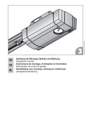
TR10A040-E RE / 06.2010<br />
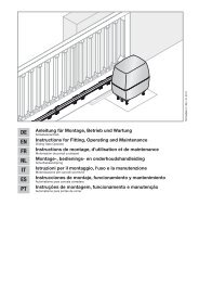
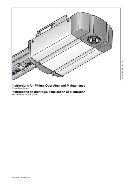
Instructions for Fitting, Operating and Maintenance<br />
Garage Door Operator<br />
Instructions de montage, d’utilisation et d’entretien<br />
Motorisation de porte de garage<br />
English / Français
2 TR10A040-E RE / 06.2010
ENGLISH ......................... 4<br />
FRANÇAIS ....................... 21<br />
...................... 40<br />
TR10A040-E RE / 06.2010 3
ENGLISH<br />
Table of Contents<br />
A Articles supplied............................................................. 2<br />
B Tools needed for assembly........................................... 2<br />
1 About These Instructions.............................................. 5<br />
1.1 Further applicable documents......................................... 5<br />
1.2 Warnings used................................................................. 5<br />
1.3 Definitions used................................................................ 5<br />
1.4 Symbols used................................................................... 5<br />
1.5 Abbreviations used........................................................... 6<br />
2 Safety Instructions................................................. 6<br />
2.1 Intended use.................................................................... 6<br />
2.2 Non-intended use............................................................. 6<br />
2.3 Fitter qualification............................................................. 6<br />
2.4 Safety instructions for fitting, maintenance,<br />
repairs and disassembly of the door system................... 6<br />
2.5 Safety instructions for fitting............................................ 6<br />
2.6 Safety instructions for initial start-up and<br />
for operation..................................................................... 6<br />
2.7 Safety instructions for using the hand transmitter........... 7<br />
2.8 Approved safety devices.................................................. 7<br />
3 Fitting............................................................................... 7<br />
3.1 Inspect door/door system................................................ 7<br />
3.2 Clearance required........................................................... 7<br />
3.3 Fitting the garage door operator...................................... 8<br />
3.4 Fitting the operator boom................................................ 8<br />
3.5 Fixing the warning sign.................................................... 9<br />
3.6 Garage door operator electrical connection.................... 9<br />
3.7 Connecting additional components/accessories............. 9<br />
4 Putting into Service...................................................... 10<br />
4.1 Notes on the operator control........................................ 10<br />
4.2 Menu selection............................................................... 11<br />
4.3 Control behaviour during initial start-up......................... 11<br />
4.4 MENU J – Adjust/set the door type............................... 11<br />
4.5 MENU 1 – Learning run/teaching in the operator.......... 11<br />
4.6 Resetting the control/restoring factory settings............. 12<br />
5 Hand Transmitter HSM 4............................................. 12<br />
5.1 Description of the hand transmitter HSM 4................... 12<br />
5.2 Inserting/changing the battery....................................... 12<br />
5.3 Restoring the factory coding.......................................... 12<br />
5.4 Excerpt <strong>fr</strong>om the declaration of conformity.................... 12<br />
6 Selecting Functions...................................................... 12<br />
6.1 MENU P.......................................................................... 13<br />
6.2 MENU 2.......................................................................... 13<br />
6.3 MENU 0 – Normal operation.......................................... 14<br />
7 Special Menus.............................................................. 14<br />
7.1 Selecting special menus................................................ 14<br />
7.2 Notes on the special menus........................................... 14<br />
7.3 MENU 3 – Automatic timed closing............................... 14<br />
7.4 MENU 4 – Safety devices............................................... 15<br />
7.5 MENU 5 – Setting the pre-warning time, option relay,<br />
and maintenance display............................................... 15<br />
7.6 MENU 6 – Force limit in the CLOSE direction................ 15<br />
7.7 MENU 7 – Behaviour in the CLOSE direction................ 16<br />
7.8 MENU 8 – Force limit in the OPEN direction.................. 16<br />
7.9 MENU 9 – Behaviour in the OPEN direction.................. 16<br />
7.10 MENU A – Maximum force............................................. 17<br />
8 Operation...................................................................... 17<br />
8.1 Instructing users............................................................. 17<br />
8.2 Function check............................................................... 18<br />
8.3 Functions of various radio codes................................... 18<br />
8.4 Behaviour during a power failure................................... 18<br />
8.5 Behaviour following a power failure............................... 18<br />
9 Inspection and Maintenance....................................... 18<br />
9.1 Replacement bulb.......................................................... 18<br />
10 Dismantling and Disposal............................................ 18<br />
11 Warranty Conditions.................................................... 18<br />
11.1 Performance................................................................... 19<br />
12 Excerpt <strong>fr</strong>om the Declaration of Incorporation......... 19<br />
13 Technical Data.............................................................. 19<br />
13.1 Operator......................................................................... 19<br />
14 Displays for Errors/Warnings and Operating<br />
Conditions..................................................................... 20<br />
14.1 Display of errors and warnings....................................... 20<br />
14.2 Display of the operating conditions of the operator....... 20<br />
Illustrated section............................................. 40<br />
* Accessory, not included as standard equipment!<br />
Dissemination as well as duplication of this document and the use<br />
and communication of its content are prohibited unless explicitly<br />
permitted. Noncompliance will result in damage compensation<br />
obligations. All rights reserved in the event of patent, utility model<br />
or design model registration. Subject to changes.<br />
4 TR10A040-E RE / 06.2010
ENGLISH<br />
Dear customer,<br />
We are delighted that you have chosen a high-quality product <strong>fr</strong>om<br />
our company.<br />
1 About These Instructions<br />
These instructions are original instructions as outlined in the<br />
EC Directive 2006/42/EC. Read through all of the instructions<br />
carefully, as they contain important information about the product.<br />
Pay attention to and follow the instructions provided, particularly<br />
the safety instructions and warnings.<br />
Please keep these instructions in a safe place and make sure that<br />
they are available to all users at all times.<br />
1.1 Further applicable documents<br />
The following documents for safe handling and maintenance of the<br />
door system must be placed at the disposal of the end user:<br />
• These instructions<br />
• The enclosed test log book<br />
• The garage door operating instructions<br />
1.2<br />
Warnings used<br />
Reversal limit<br />
If a safety device is activated, door travel is triggered in the<br />
opposite direction (reverse cycle) up to the reversal limit shortly<br />
before the CLOSE end-of-travel position. If this limit is passed, no<br />
reversal occurs to ensure that the door reaches the end-of-travel<br />
position without disrupting travel.<br />
Partial opening<br />
Individually adjustable second opening height to ventilate the<br />
garage.<br />
Path of travel<br />
The distance the door takes to traverse <strong>fr</strong>om the OPEN end-oftravel<br />
position to the CLOSE end-of-travel position.<br />
Pre-warning time<br />
The time between the travel command (impulse) and the start of<br />
travel.<br />
1.4 Symbols used<br />
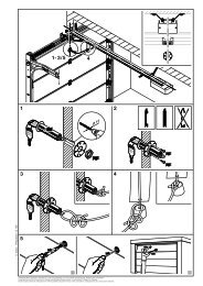
The illustrated section shows how to fit an operator on a sectional<br />
door. Deviations for fitting with an up-and-over door are also<br />
shown. For this purpose, the following letters are assigned to the<br />
figures:<br />
The general warning symbol indicates a danger that can<br />
lead to injury or death. In the text, the general warning symbol<br />
will be used in connection with the caution levels described<br />
below. In the illustrated section, an additional instruction refers<br />
back to the explanation in the text.<br />
DANGER<br />
Indicates a danger that leads directly to death or serious injuries.<br />
a = Sectional door<br />
b = Up-and-over door<br />
WARNING<br />
Indicates a danger that can lead to death or serious injuries.<br />
CAUTION<br />
Indicates a danger that can lead to minor or moderate injuries.<br />
ATTENTION<br />
Indicates a danger that can lead to damage or destruction of<br />
the product.<br />
1.3 Definitions used<br />
Automatic timed closing<br />
Automatic timed closing of the door after a set time has elapsed<br />
and after reaching the OPEN end-of-travel position or partial<br />
opening.<br />
All dimensions in the illustrated section are in [mm].<br />
Symbols:<br />
See text section<br />
In the example, 2.2 means: See text section,<br />
section 2.2<br />
Important advice to prevent injury to persons<br />
and damage to property<br />
High exertion of force<br />
Impulse sequence control<br />
With each push of the button, the door is started against the<br />
previous direction of travel, or the motion of the door is stopped.<br />
Learning runs<br />
Door travels in which the travel and the forces needed for moving<br />
the door are taught in.<br />
Check for smooth running<br />
Normal operation<br />
Door travel with the taught-in travel distances and forces.<br />
Safety reversal<br />
Door travel in the opposite direction when the safety device or<br />
force limit is activated.<br />
Use protective gloves<br />
TR10A040-E RE / 06.2010 5
ENGLISH<br />
1.5<br />
Slow flashing in the 7-segment display<br />
Rapid flashing in the 7-segment display<br />
Abbreviations used<br />
Colour code for cables, single conductors and components<br />
The abbreviations of the colours for identifying the cables,<br />
conductors and components comply with the international<br />
colour code according to IEC 757:<br />
WH<br />
White<br />
BN<br />
Brown<br />
GN<br />
Green<br />
YE<br />
Yellow<br />
Article designations<br />
HE 2<br />
2-channel receiver<br />
HE 3<br />
3-channel receiver<br />
IT 1b Internal push button with illuminated impulse<br />
button<br />
IT 3b Internal push button with illuminated impulse<br />
button, additional buttons for light on/off and<br />
operator on/off<br />
EL 101 One-way photocell<br />
STK<br />
Wicket door contact<br />
SKS<br />
Activating kit for closing edge safety device<br />
VL<br />
Activating kit for leading photocell<br />
HSM 4 4-button mini hand transmitter<br />
HOR 1 Option relay<br />
UAP 1 Universal adapter print<br />
HNA 18 Emergency battery<br />
SLK<br />
Yellow LED warning light<br />
2 Safety Instructions<br />
ATTENTION:<br />
IMPORTANT SAFETY INSTRUCTIONS.<br />
FOR THE SAFETY OF PERSONS, IT IS IMPORTANT TO COMPLY<br />
WITH THE FOLLOWING INSTRUCTIONS. THESE INSTRUCTIONS<br />
MUST BE KEPT.<br />
2.1 Intended use<br />
The garage door operator is intended for impulse operation of<br />
spring compensated sectional and up-and-over doors, as well as<br />
counterbalanced retractable up-and-over doors. Depending on the<br />
type of operator, the operator can be used in private/noncommercial<br />
areas or in commercial areas (e.g. in underground and<br />
collective garages).<br />
Note the manufacturer's specifications regarding the door and<br />
operator combination. Potential hazards as outlined in<br />
DIN EN 13241-1 are avoided by construction and fitting according<br />
to our guidelines. Door systems which are located in a public area<br />
and only have one protective device, such as a force limit, may<br />
only be operated under supervision.<br />
The garage door operator is designed for operation in dry areas.<br />
2.2 Non-intended use<br />
The operator must not be used for doors without a safety catch.<br />
2.3 Fitter qualification<br />
Only correct fitting and maintenance in compliance with the<br />
instructions by a competent/specialist company or a competent/<br />
qualified person ensures safe and flawless operation of the<br />
system. According to EN 12635, a specialist is a person with<br />
suitable training, specialist knowledge and practical experience<br />
sufficient to correctly and safely fit, test, and maintain a door<br />
system.<br />
2.4<br />
Safety instructions for fitting, maintenance, repairs<br />
and disassembly of the door system<br />
DANGER<br />
Compensating springs are under high tension<br />
▶ See warning in Section 3.1<br />
WARNING<br />
Danger of injury due to unexpected door travel<br />
▶ See warning in Section 9<br />
Fitting, maintenance, repairs, and disassembly of the door system<br />
and garage door operator must be performed by a specialist.<br />
▶ In the event of a failure of the garage door operator, a<br />
specialist must be commissioned immediately for the<br />
inspection or repair work.<br />
2.5 Safety instructions for fitting<br />
The specialist must ensure that the applicable regulations on<br />
occupational safety, as well as the regulations on the operation of<br />
electrical devices, are followed during assembly work. In the<br />
process, the relevant national guidelines must be observed.<br />
Potential hazards as outlined in DIN EN 13241-1 are avoided by<br />
construction and fitting according to our guidelines.<br />
The garage ceiling must guarantee secure fastening of the<br />
operator. For ceilings which are too high or too light, the operator<br />
must be fastened on additional struts.<br />
Mains voltage<br />
▶ See warning in Section 3.6<br />
Unsuitable fixing material<br />
▶ See warning in Section 3.3<br />
Danger to life <strong>fr</strong>om the rope<br />
▶ See warning in Section 3.3<br />
WARNING<br />
Danger<br />
Danger of injury due to unwanted door travel<br />
▶ See warning in Section 3.3<br />
2.6<br />
Safety instructions for initial start-up and for<br />
operation<br />
WARNING<br />
Danger of injury during door travel<br />
▶ See warning in Section 4<br />
6 TR10A040-E RE / 06.2010
ENGLISH<br />
Danger of crushing in the boom<br />
▶ See warning in Section 4<br />
Caution<br />
Danger of injury <strong>fr</strong>om the cord knob<br />
▶ See warning in Section 4<br />
Danger of injuries due to the hot lamp<br />
▶ See warning in Section 4 and Section 8<br />
Danger of injury due to the force value being set too high<br />
▶ See warning in Section 7.6 and Section 7.8<br />
Danger of injury resulting <strong>fr</strong>om uncontrolled door movement<br />
in the CLOSE direction if the torsion spring breaks and the<br />
slide carriage is released.<br />
▶ See warning in Section 8<br />
2.7<br />
Safety instructions for using the hand transmitter<br />
WARNING<br />
Danger of injury during door travel<br />
▶ See warning in Section 5<br />
Caution<br />
Danger of injuries due to unwanted door travel<br />
▶ See warning in Section 5<br />
2.8 Approved safety devices<br />
Safety relevant functions or components of the control <strong>fr</strong>om our<br />
company, such as the power limit, external photocells/switching<br />
strips, when installed, have been designed and approved in<br />
accordance with category 2, PL “c” of EN ISO 13849-1:2008.<br />
WARNING<br />
Danger of injuries due to faulty safety equipment<br />
▶ See warning in Section 4.5.1<br />
3<br />
Fitting<br />
ATTENTION:<br />
IMPORTANT INSTRUCTIONS FOR SAFE INSTALLATION.<br />
OBSERVE ALL INSTRUCTIONS, INCORRECT FITTING COULD<br />
RESULT IN SERIOUS INJURY.<br />
3.1 Inspect door/door system<br />
DANGER<br />
Compensating springs are under high tension<br />
Serious injuries may occur while adjusting or loosening the<br />
compensating springs!<br />
▶ For your own safety, only have a specialist conduct work<br />
on the door compensating springs and, if necessary,<br />
maintenance and repair work!<br />
▶ Never try to replace, adjust, repair or reposition the<br />
compensating springs for the counterbalance of the door or<br />
the spring mountings yourself.<br />
▶ Furthermore, inspect the entire door system (joints, door<br />
bearings, cables, springs and fastening parts) for wear and<br />
possible damage.<br />
▶ Check for the presence of rust, corrosion, and cracks.<br />
A fault in the door system or an incorrectly aligned door may<br />
lead to serious injuries!<br />
▶ Do not use the door system if repair or adjustment work<br />
must be conducted!<br />
The design of the operator is not suitable nor intended for the<br />
opening and closing of sluggish doors, i.e. doors that can no<br />
longer be opened or closed manually, or can only be opened/<br />
closed manually with difficulty.<br />
The door must be in perfect mechanical condition and balanced,<br />
so that it is easy to operate by hand (EN 12604).<br />
▶ Lift the door by approx. one meter and let it go. The door<br />
should stay in this position and neither move downward nor<br />
upward. If the door does move in either direction, there is a<br />
danger that the compensating springs/weights are not<br />
properly adjusted or are defective. In this case, increased<br />
wear and malfunctioning of the door system can be expected.<br />
▶ Check whether the door can be opened and closed correctly.<br />
▶ The mechanical locking devices of the door that are not<br />
needed with a garage door operator must be put out of<br />
commission.<br />
This especially includes the locking mechanisms of the door<br />
lock (see Section 3.3).<br />
▶<br />
Change to the illustrated section for the fitting and initial<br />
operation. Observe the respective text section when you<br />
are prompted to by the symbol for the text reference.<br />
3.2 Clearance required<br />
The clearance between the highest point of the door and the<br />
ceiling (also when opening the door) must be at least 30 mm<br />
(see Figures 1.1a/1.2b).<br />
▶ Check this dimension!<br />
If the clearance is smaller, the operator can also be mounted<br />
behind the opened door if enough space is available. In such<br />
cases, an extended fitting bracket has to be used, which must be<br />
ordered separately. In addition, the garage door operator can be<br />
arranged up to max. 50 cm off-centre. Exceptions are sectional<br />
doors with a high-lift (high-lift track application H); a special fitting<br />
is required for this arrangement. The electrical outlet necessary for<br />
the electrical connection should be fitted approx. 50 cm <strong>fr</strong>om the<br />
operator head. Please check these dimensions!<br />
TR10A040-E RE / 06.2010 7
ENGLISH<br />
3.3 Fitting the garage door operator<br />
WARNING<br />
Unsuitable fixing material<br />
Use of unsuitable fixing material may mean that the operator is<br />
insecurely attached and could come loose.<br />
▶ The fitter must check that the fitting materials supplied are<br />
suitable for the purpose and the intended fitting location.<br />
▶ Only use the provided fixing materials (plugs) in concrete<br />
≥ B15 (see Figures 1.6a/1.8b/2.4).<br />
WARNING<br />
Danger to life <strong>fr</strong>om the rope<br />
A running rope may lead to strangulation.<br />
▶ Remove the rope while fitting the operator (see Figure 1.2a).<br />
WARNING<br />
Danger of injury due to unwanted door<br />
travel<br />
Incorrect assembly or handling of the<br />
operator, may trigger unwanted door travel<br />
that may result in persons or objects being<br />
trapped.<br />
▶ Follow all the instructions provided in<br />
this manual.<br />
Incorrectly attached control devices (e.g.<br />
buttons) may trigger unwanted door travel.<br />
Persons or objects may be trapped as a<br />
result.<br />
▶ Install control devices at a height of at<br />
least 1.5 m (out of the reach of children).<br />
▶ Fit permanently installed control<br />
devices (such as buttons, etc.) within<br />
sight of the door, but away <strong>fr</strong>om<br />
moving parts.<br />
ATTENTION<br />
Damage caused by dirt<br />
Drilling dust and chippings can lead to malfunctions.<br />
▶ Cover the operator during drilling work.<br />
Note:<br />
An emergency release is necessary for garages without a second<br />
entrance that prevents the possibility of being locked out; this<br />
must be ordered separately.<br />
▶ Check the emergency release monthly for proper function.<br />
1. Completely disassemble the mechanical door locking on the<br />
sectional door (see Figure 1.3a).<br />
2. For sectional doors with centre door locking, arrange the lintel<br />
joint and link bracket off-centre (see Figure 1.5a).<br />
3. With an off-centre reinforcement profile on the sectional door,<br />
fit the link bracket on the nearest reinforcement profile to the<br />
left or right (see Figure 1a).<br />
Note:<br />
In a deviation <strong>fr</strong>om figure 1.5a: Use the 5 x 35 woodscrews <strong>fr</strong>om<br />
the door accessory pack (hole Ø 3 mm) for timber doors.<br />
4. The mechanical door locking on an up-and-over door must<br />
be rendered inoperable (see Figures 1.3b/1.4b/1.5b).<br />
For door models not covered here, block the catches on site.<br />
5. In a deviation <strong>fr</strong>om the Figures 1.6b/1.7b: The lintel joint and<br />
link bracket must be attached off-centre for up-and-over<br />
doors with ornamental iron door handles.<br />
Note:<br />
On N80 doors with timber infill, use the bottom holes on the lintel<br />
joint for fitting (see Figure 1.7b).<br />
3.4<br />
Fitting the operator boom<br />
Notes:<br />
• Before the boom is fitted on the lintel or under the ceiling, the<br />
engaged slide carriage must be moved approx. 20 cm <strong>fr</strong>om<br />
the CLOSE end-of-travel position in the OPEN direction<br />
(see Section 3.4.1, Boom operating modes) (see Figure 2.1).<br />
This is no longer possible with an engaged carriage as soon<br />
as the end stops and operator have been fitted.<br />
• For operators used in underground and collective garages, it<br />
is necessary to fix the boom under the ceiling of the garage<br />
using a second suspension (see Figure 2.4 and Figure 2.5).<br />
• Only use the booms recommended by us for the garage door<br />
operators – depending on the respective purpose of use<br />
(see product information).<br />
3.4.1 Boom operating modes<br />
There are two different operating modes with the boom:<br />
• Manual operation<br />
• Automated operation<br />
Manual operation<br />
▶ See Figure 4<br />
The slide carriage is disengaged <strong>fr</strong>om the belt lock to enable the<br />
door to be moved by hand.<br />
For disengaging the slide carriage:<br />
▶ Pull on the cord of the mechanical release.<br />
Caution<br />
Danger of injury resulting <strong>fr</strong>om uncontrolled door movement<br />
in the CLOSE direction if the torsion spring breaks and the<br />
slide carriage is released.<br />
The slide carriages may decouple automatically unless a retrofit<br />
set is fitted.<br />
▶ The fitter responsible must install a retrofit set on the slide<br />
carriage if the following prerequisites are at hand:<br />
— The standard DIN EN 13241-1 applies.<br />
— The garage door operator is retrofitted to a Hörmann<br />
sectional door without spring safety device (BR30)<br />
by a technical expert.<br />
This set comprises a screw that secures the slide carriage<br />
against uncontrolled unlocking as well as a new cord knob sign<br />
where the images show how the set and the slide carriage can<br />
be handled for the two operating modes of the operator boom.<br />
Note:<br />
The use of an emergency release or an emergency release lock<br />
is not possible in conjunction with the retrofit set.<br />
Automated operation<br />
▶ See Figure 6<br />
The belt lock is engaged in the slide carriage to enable the door to<br />
be moved with the operator.<br />
For preparing the slide carriage for engaging:<br />
1. Press the green knob.<br />
2. Move the belt in the direction of the slide carriage until the<br />
belt lock engages.<br />
8 TR10A040-E RE / 06.2010
ENGLISH<br />
Caution<br />
Danger of crushing in the boom<br />
Do not reach into the boom with your fingers during door travel,<br />
as this can cause crushing.<br />
▶ Do not reach into the boom during door travel<br />
3.4.2 Determining the door end-of-travel positions by<br />
fitting the end stops<br />
1. Loosely position the end stop for the OPEN end-of-travel<br />
position in the boom between the slide carriage and operator.<br />
2. Push the door into the OPEN end-of-travel position by hand.<br />
This will push the end stop into the correct position.<br />
3. Tighten the end stop for the OPEN end-of-travel position (see<br />
Figure 5.1).<br />
Note:<br />
If the door should not reach the complete passage height in the<br />
OPEN end-of-travel position, the end stop can be removed so that<br />
the integrated end stop (on the operator head) is used.<br />
4. Loosely position the end stop for the CLOSE end-of-travel<br />
position in the boom between the slide carriage and door.<br />
5. Push the door into the CLOSE end-of-travel position by hand.<br />
This will push the end stop near to the correct position.<br />
6. After reaching the CLOSE end-of-travel position move the<br />
end stop by approx. 1 cm in the CLOSE direction and fix the<br />
end stop (see Figure 5.2).<br />
Note:<br />
If the door cannot be easily pushed manually into the desired<br />
OPEN or CLOSE end-of-travel position, this means that the door<br />
mechanism is too stiff for operation with the garage door operator<br />
and must be inspected (see Section 3.1)!<br />
3.4.3 Tension of the toothed belt<br />
The toothed belt of the operator boom is tensioned optimally<br />
ex-factory. During the start-up and slow-down phase, with larger<br />
doors it is possible that the belt will briefly hang out of the boom<br />
profile. However, this does not result in any technical<br />
consequences and does not negatively affect the function and<br />
service life of the operator.<br />
3.5 Fixing the warning sign<br />
Fix the sign warning about getting trapped in a noticeable, cleaned<br />
and degreased place, for example, near to the permanently<br />
installed button for moving the operator.<br />
▶ See Figure 8<br />
3.6 Garage door operator electrical connection<br />
Mains voltage<br />
Danger<br />
Contact with the mains voltage presents the danger of a deadly<br />
electric shock.<br />
For that reason, observe the following warnings under all<br />
circumstances:<br />
▶ Electrical connections may only be made by a qualified<br />
electrician.<br />
▶ The on-site electrical installation must conform to the<br />
applicable protective regulations (230/240 V AC, 50/60 Hz)!<br />
▶ The mains plug must be disconnected before any work is<br />
performed on the operator.<br />
ATTENTION<br />
External voltage on the connecting terminals<br />
External voltage on the connecting terminals of the control will<br />
destroy the electronics.<br />
▶ Do not apply any mains voltage (230/240 V AC) to the<br />
connecting terminals on the control.<br />
To prevent malfunctions:<br />
▶ The connection cables of the operator (24 V DC) must be laid<br />
in a separate installation system <strong>fr</strong>om the other supply cables<br />
(230 V AC).<br />
3.6.1 Electrical connection/connecting terminals<br />
▶ See Figure 9<br />
▶ Remove the plug cover to access the connecting terminals.<br />
Note:<br />
All connecting terminals can be assigned several times. However,<br />
observe the following thicknesses (see Figure 10):<br />
• Minimum thickness: 1 x 0.5 mm2<br />
• Maximum thickness: 1 x 2.5 mm2<br />
Accessories with special functions can be connected to the BUS<br />
connecting terminal.<br />
3.7<br />
Connecting additional components/accessories<br />
Note:<br />
Loading of the operator by all accessories: max. 250 mA.<br />
3.7.1 Connecting an external radio receiver *<br />
An additional 2-channel receiver can also be connected to this<br />
garage door operator for the Impulse, Light and Partial opening<br />
functions. Insert the plug of the receiver in the corresponding slot<br />
(see Figure 9).<br />
If the receivers have the same radio <strong>fr</strong>equency, the data in the<br />
integral radio module must be deleted (see Section 6.1.2).<br />
Note:<br />
The aerial wire of the radio receiver should not come into contact<br />
with metal objects (nails, bracing, etc.). The best orientation to<br />
achieve an optimum range must be established by trial and error.<br />
When used at the same time, GSM 900 mobile phones can affect<br />
the range of the radio remote control.<br />
With a 2-channel receiver, the first channel is always for the<br />
impulse sequence control function. The second channel can be<br />
used to actuate the operator light or for partial opening<br />
(see Section 6.2.3).<br />
3.7.2 External impulse button * to start or stop door runs<br />
One or more buttons with normally open contacts (volt-<strong>fr</strong>ee), such<br />
as internal push buttons or key switches, can be connected in<br />
parallel (see Figure 11).<br />
3.7.3 Internal push button IT 3b *<br />
▶ See Figure 12<br />
3.7.4 Impulse button to start or stop door runs<br />
▶ See Figure 12.1<br />
3.7.5 Light button to switch the operator light on and off<br />
▶ See Figure 12.2<br />
3.7.6 Button to switch all control elements on and off<br />
▶ See Figure 12.3<br />
* Accessory, not included as standard equipment!<br />
TR10A040-E RE / 06.2010 9
ENGLISH<br />
3.7.7<br />
2-wire photocell * (dynamic)<br />
Note:<br />
Follow the fitting instructions when mounting photocells.<br />
▶ Connect the photocell as shown in Figure 13.<br />
After the photocell triggers, the operator stops and a safety<br />
reversal of the door is performed to the OPEN end-of-travel<br />
position.<br />
3.7.8 Self-testing wicket door contact *<br />
▶ Connect wicket door contacts that switch to ground (0 V) as<br />
shown in Figure 14.<br />
3.7.9 Closing edge safety device *<br />
▶ Connect closing edge safety devices that switch to ground<br />
(0 V) as shown in Figure 15.<br />
After the closing edge safety device triggers, the operator stops<br />
and the door reverses in the OPEN direction.<br />
3.7.10 Option relay HOR 1 *<br />
▶ See Figure 16<br />
Option relay HOR 1 is required to connect an external lamp or<br />
warning light (programming via menu 5).<br />
3.7.11 Universal adapter print UAP 1 *<br />
▶ See Figure 17<br />
The universal adapter print UAP 1 can be used:<br />
• For choosing a direction (Open/Stop/Close) via external<br />
control elements<br />
• For control of the operator light and second opening height<br />
via external command units<br />
• For OPEN and CLOSE limit switch reporting<br />
• For the option relay (programming via menu 5).<br />
3.7.12 Emergency battery HNA 18 *<br />
▶ See Figure 18<br />
To enable door movement in the event of a mains failure, an<br />
optional emergency battery can be connected. In the case of a<br />
mains failure, the system automatically switches to battery<br />
operation. During battery operation, the operator light remains<br />
switched off.<br />
WARNING<br />
Danger of injury due to unexpected door travel<br />
Unexpected door travel can result when the emergency battery<br />
is still connected despite the mains plug being pulled out.<br />
▶ Pull out the mains plug and the plug of the emergency<br />
battery when performing all work on the door system.<br />
4 Putting into Service<br />
WARNING<br />
Danger of injury during door travel<br />
If people or objects are in the area around<br />
the door while the door is in motion, this<br />
can lead to injuries or damage.<br />
▶ Children are not allowed to play near<br />
the door system.<br />
▶ Make sure that no persons or objects<br />
are in the door's travel range.<br />
▶ If the door system has only one safety<br />
feature, only operate the garage door<br />
operator if you are within sight of the<br />
door's area of travel.<br />
▶ Monitor the door travel until the door<br />
has reached the end-of-travel position.<br />
▶ Only drive or pass through remote<br />
control door systems if the door is in<br />
the OPEN end-of-travel position!<br />
▶ Never stay standing under the open<br />
door.<br />
Caution<br />
Danger of crushing in the boom<br />
Do not reach into the boom with your fingers during door travel,<br />
as this can cause crushing.<br />
▶ Do not reach into the boom during door travel.<br />
Caution<br />
Danger of injury <strong>fr</strong>om the cord knob<br />
If you hang on the cord knob, you may fall and injure yourself.<br />
The operator could break away and injure persons or damage<br />
objects that are located underneath, or the operator itself could<br />
be destroyed.<br />
▶ Do not hang on the cord knob with your body weight.<br />
Caution<br />
Danger of injuries due to the hot lamp<br />
Touching the cold-light reflector lamp during or immediately<br />
following operation can lead to burns.<br />
▶ Do not touch the cold-light reflector lamp if it is switched<br />
on or was recently switched on.<br />
4.1 Notes on the operator control<br />
The operator control includes 13 menus that contain many user<br />
functions.<br />
However, two menus are needed for initial start-up of the operator.<br />
• To adjust/set the door type (menu J)<br />
• To teach in door travel (menu 1)<br />
Note:<br />
Menus J, 1, P and 2 are initial start-up/function selection menus<br />
and customer menus; menus 3, 4, 5, 6, 7, 8, 9 and A are special<br />
menus and should only be changed if needed.<br />
* Accessory, not included as standard equipment!<br />
10 TR10A040-E RE / 06.2010
ENGLISH<br />
4.2<br />
▶<br />
Menu selection<br />
Press the PRG button to select a menu.<br />
If the operator has been taught in, the PRG button must be held<br />
down for 5 seconds in order to be able to change the menus.<br />
Afterwards, switch to the next menu by pressing this button again.<br />
After reaching menu P, the display switches to menu 0.<br />
Note:<br />
The menus are activated for approx. 60 seconds, after which the<br />
system goes back to menu 0.<br />
4.3 Control behaviour during initial start-up<br />
During initial start-up, the control automatically switches to<br />
menu J.<br />
▶ After you have set the door type, press the PRG button to go<br />
to menu 1.<br />
Once the learning runs have been completed, the system<br />
automatically goes to menu 0 (normal operation).<br />
4.4 MENU J – Adjust/set the door type<br />
▶ See Figure 21<br />
Note:<br />
Menu J can only be accessed during initial start-up or after<br />
resetting the system to the factory settings<br />
(see Section 4.6, Figure 34).<br />
This menu helps you optimally adjust the operator to the<br />
respective door.<br />
To be able to change a parameter:<br />
▶ Press the PRG button until the display begins flashing rapidly.<br />
To scroll through the menu:<br />
▶ Press the or button.<br />
To change a parameter:<br />
1. Select the parameter to be set.<br />
2. Press the PRG button until the decimal point also flashes.<br />
Display<br />
Operator on<br />
Active settings<br />
Menu 4 Menu 7 Menu 9<br />
Sectional door 0, 2, 5 1, 2, 5 1, 3,<br />
5, 9<br />
Up-and-over 0, 2, 5 0, 2, 5 1, 3,<br />
door 1) 5, 8<br />
Retractable 0, 2, 5 1, 2, 5 0, 3,<br />
door 2)<br />
up-and-over<br />
6, 9<br />
Side sectional<br />
door, ...<br />
0, 2, 5 1, 2, 5 1, 3, 5, 8,<br />
A<br />
3) Sliding door 4) 0, 4, 5 1, 2, 5 1, 3, 5, 8,<br />
b<br />
1) A door swinging outwards<br />
2) A door tilting inwards<br />
3) Dependent on the operator type<br />
4) With this door type, an 8k2 resistance contact strip must be fitted to<br />
the secondary closing edge for the OPEN direction and connected to<br />
the operator via the 8k2-1T decoder unit.<br />
Note:<br />
▶ Set parameter 3 for hinged doors.<br />
4.5 MENU 1 – Learning run/teaching in the operator<br />
▶ With the PRG button, select menu 1.<br />
The operator is adjusted to the door in this menu. The travel<br />
length, required force for opening and closing, and any connected<br />
safety devices are automatically taught in and saved.<br />
4.5.1 Teaching in the end-of-travel positions and<br />
connected safety devices<br />
▶ See Figure 22<br />
Notes:<br />
• Safety devices must be fitted and connected before teaching<br />
in the operator.<br />
• If further safety devices are connected at a later point, a new<br />
learning run is required for automatic learning on the operator<br />
or the appropriate parameter must be manually set in menu 4.<br />
Before the first learning run in the CLOSE direction, the system<br />
checks whether any safety devices are connected. If this is the<br />
case, menu 4 is set automatically.<br />
Note:<br />
The slide carriage must be engaged (see Figure 6) and there may<br />
not be any obstructions in the function range of the safety devices!<br />
▶ If needed, put the control into learning mode by switching to<br />
menu 1 with the PRG button.<br />
A flashing L will appear in the display after the 1.<br />
1. Press the button.<br />
The door will move to the OPEN end-of-travel position.<br />
2. Press the button.<br />
The door moves to the CLOSE end-of-travel position. The<br />
door fully opens and a rapidly flashing L appears in the display.<br />
3. Press the button again.<br />
The door moves to the CLOSE end-of-travel position. After<br />
the door reaches the CLOSE end-of-travel position, it<br />
automatically opens again completely. The next cycle<br />
(CLOSE and OPEN) will be automatically performed by the<br />
operator.<br />
A number flashes after reaching the OPEN end-of-travel position.<br />
This indicates the maximum detected force.<br />
Note:<br />
The displays of the maximum detected force have the following<br />
meanings:<br />
0-2 Optimum force conditions<br />
3-9 Poor force conditions<br />
The door system must be inspected or readjusted.<br />
WARNING<br />
Danger of injuries due to faulty safety equipment<br />
In the event of a malfunction, there is a danger of injuries due to<br />
faulty safety equipment<br />
▶ After the learning runs, the person commissioning must<br />
check the function(s) of the safety equipment as well as the<br />
settings in menu 4.<br />
The system is ready for operation only after this.<br />
Note:<br />
The garage door operator motor is equipped with thermal overload<br />
protection. If two fast OPEN cycles take place within two minutes,<br />
overload protection reduces the travel speed, i.e. OPEN and<br />
CLOSE runs are at the same speed. After a waiting period of two<br />
minutes, the next OPEN run will be fast.<br />
If the door behaviour has to be changed:<br />
▶ Select the required settings in menus 7 and 9.<br />
TR10A040-E RE / 06.2010 11
ENGLISH<br />
4.6 Resetting the control/restoring factory settings<br />
▶ See Figure 34<br />
To reset the control:<br />
1. Disconnect the mains plug and, if necessary, the plug of the<br />
emergency battery.<br />
2. Press and hold the PRG button.<br />
3. Reconnect the mains plug.<br />
4. Release the PRG button once C is displayed.<br />
5. Adjust the operator and teach it in.<br />
Note:<br />
The taught-in radio codes (Impulse/Light/Partial opening) are not<br />
changed.<br />
To delete all radio codes for a function:<br />
▶ See Section 6.1.2<br />
5 Hand Transmitter HSM 4<br />
WARNING<br />
Danger of injury during door travel<br />
Persons may be injured by door travel if the<br />
hand transmitter is actuated.<br />
▶ Make sure that the hand transmitters<br />
are kept away <strong>fr</strong>om children and cab<br />
only be used by people who have<br />
been instructed on how the remotecontrol<br />
door functions!<br />
▶ If the door has only one safety feature,<br />
only operate the hand transmitter if<br />
you are within sight of the door!<br />
▶ Only drive or pass through remote<br />
control door systems if the door is in<br />
the OPEN end-of-travel position!<br />
▶ Never stay standing under the open<br />
door.<br />
▶ Please note that unintended door<br />
cycles may occur if a hand transmitter<br />
button is accidentally pressed (e.g. if<br />
stored in a pocket/handbag).<br />
Caution<br />
Danger of injuries due to unwanted door travel<br />
Unwanted door travel may occur while teaching in the radio<br />
system.<br />
▶ Pay attention that no persons or objects are in the door's<br />
travel range when teaching in the radio system.<br />
ATTENTION<br />
Functional disturbances caused by environmental<br />
conditions<br />
These conditions can impair function!<br />
Protect the hand transmitter <strong>fr</strong>om the following conditions:<br />
• Direct sunlight (perm. ambient temperature: -20°C to<br />
+60°C)<br />
• Moisture<br />
• Dust<br />
Notes:<br />
• If there is no separate garage entrance, perform all<br />
programming changes and extensions while standing in the<br />
garage.<br />
• Perform a functional check after programming or extending<br />
the remote control system.<br />
• Only use original components for the initial start-up or for<br />
extending the remote control system.<br />
• Local conditions may affect the range of the radio system.<br />
Moreover, when used at the same time, GSM 900 mobile<br />
phones can affect the range.<br />
5.1 Description of the hand transmitter HSM 4<br />
▶ See Figure 23<br />
1 LED<br />
2 Hand transmitter button<br />
3 Battery compartment cover<br />
4 Battery<br />
5 Reset button<br />
6 Hand transmitter holder<br />
5.2 Inserting/changing the battery<br />
▶ See Figure 23<br />
▶ Use only the battery type 23 A.<br />
5.3 Restoring the factory coding<br />
▶ See Figure 23<br />
A radio code is stored for each hand transmitter button.<br />
The original factory code can be restored by going through the<br />
following steps.<br />
Note:<br />
The following steps are only required in the case of inadvertent<br />
extension or teach-in processes.<br />
1. Open the battery compartment cover.<br />
The reset button (5) is accessible on the circuit board.<br />
ATTENTION<br />
Destruction of the button<br />
▶ Do not use any pointed objects or excessive force when<br />
pressing the button.<br />
2. Carefully press the reset button with a blunt object and keep<br />
it pressed.<br />
3. Press the hand transmitter button to be coded and keep it<br />
pressed.<br />
The transmitter LED will flash slowly.<br />
4. If you keep the small button pressed until the slow flashing<br />
stops, the hand transmitter button will be assigned with the<br />
original factory coding and the LED will start to flash faster.<br />
5. Close the battery compartment cover.<br />
The factory code is now restored.<br />
5.4 Excerpt <strong>fr</strong>om the declaration of conformity<br />
Conformity of the abovementioned product with the requirements<br />
of the directives according to article 3 of the R&TTE directives<br />
1999/5/EC was verified by compliance with the following<br />
standards:<br />
• EN 60950:2000<br />
• EN 300 220-1<br />
• EN 300 220-3<br />
• EN 301 489-1<br />
• EN 300 489-3<br />
The original declaration of conformity can be requested <strong>fr</strong>om the<br />
manufacturer.<br />
6<br />
Selecting Functions<br />
Note:<br />
In the menus that consist of several parameter blocks, only one<br />
parameter can be activated per block.<br />
12 TR10A040-E RE / 06.2010
ENGLISH<br />
6.1 MENU P<br />
The following radio codes can be taught in in this menu:<br />
Function Parameter Image<br />
Impulse sequence control 0 24.1<br />
Light function 1 24.2<br />
Partial opening 2 24.3<br />
The following functions can also be set in this menu:<br />
• Partial opening position (parameter 3)<br />
• SKS/VL reversal limit (parameter 4)<br />
Display Radio Function<br />
Channel 1<br />
Channel 2<br />
Channel 3<br />
Impulse<br />
Light<br />
Partial opening<br />
– Setting the partial opening<br />
position<br />
– SKS/VL reversal limit<br />
(SKS is preset)<br />
6.1.1 Teaching in a radio code on the integral radio<br />
receiver<br />
▶ See Figures 24.1/24.2/24.3<br />
To teach in a radio code on the integral radio receiver, the following<br />
prerequisites must be met:<br />
• The operator is at rest.<br />
• The warning or hold-open phase is not active.<br />
Note:<br />
A maximum of 12 different codes can be taught in per function.<br />
If more than 12 codes are taught in, the first one will be deleted.<br />
1. Select menu P.<br />
2. Select parameter 0, 1 or 2.<br />
3. Press the PRG button until the decimal point slowly flashes.<br />
4. Press a button on the hand transmitter.<br />
— The receiver recognises the transmitted code.<br />
— The display flashes rapidly.<br />
— The code is taught in and stored.<br />
— The operator remains in the parameter selected in<br />
menu P.<br />
5. Change to normal operation by pressing the PRG button<br />
(menu 0).<br />
Note:<br />
If the same radio code has been taught in for two different<br />
functions, the code for the first taught-in function will be deleted<br />
and the new one will be valid.<br />
6.1.2 Deleting all radio codes for a function<br />
To delete all of a function’s radio codes on the integral radio<br />
receiver, the following prerequisites must be met:<br />
• The operator is at rest.<br />
• The warning or hold-open phase is not active.<br />
1. Select menu P.<br />
2. Select parameter 0, 1 or 2.<br />
3. Press the PRG button until the decimal point slowly flashes.<br />
4. Press the and buttons simultaneously.<br />
The decimal point will stop flashing. All codes for this function<br />
have been deleted.<br />
6.1.3 Setting the partial opening position<br />
▶ See Figure 24.4<br />
Note:<br />
The Partial opening position can only be set if the operator has<br />
been taught in.<br />
Partial opening can be set in menu P via parameter 3:<br />
The display flashes slowly.<br />
1. Press the PRG button until the decimal point flashes.<br />
2.<br />
The parameter is activated.<br />
Move the door in press-and-hold operation with the and<br />
buttons.<br />
3. Once the desired position is reached, press the PRG button<br />
until the display begins flashing rapidly.<br />
The decimal point goes out and the display flashes slowly.<br />
Note:<br />
The setting range for Partial opening is <strong>fr</strong>om the OPEN<br />
end‐of‐travel position to approx. 120 mm (slide travel) before the<br />
CLOSE end-of-travel position. The standard factory setting is<br />
approx. 260 mm (slide travel) before the CLOSE end-of-travel<br />
position.<br />
6.1.4 Setting the SKS/VL reversal limit<br />
▶ See Figure 24.5<br />
Note:<br />
The SKS/VL reversal limit can only be set under the following<br />
prerequisites:<br />
• The operator has been taught in.<br />
• Parameter 3 or 4 is activated in menu 4.<br />
In menu P, the SKS/VL reversal limit can be set via parameter 4.<br />
The SKS/VL reversal limit is preset before the CLOSE end-of-travel<br />
position for the closing edge safety device.<br />
To set the SKS/VL reversal limit:<br />
1. Press the PRG button until the decimal point is illuminated.<br />
Parameter 4 is thus selected and activated.<br />
2. Move the operator into the OPEN end-of-travel position<br />
with the button.<br />
3. Place a test body in the centre of the door<br />
(max. 300 x 50 x 16.25 mm, e.g. a folding rule) on the ground<br />
so that its smallest edge is towards the top and in the range<br />
of the leading photocell.<br />
4. Press the button.<br />
— The door moves until the test body is detected by<br />
the safety device.<br />
— The position is stored and checked for plausibility.<br />
— The operator reverses.<br />
— The display flashes rapidly if the procedure was successful.<br />
— The parameter then flashes slowly without a decimal<br />
point.<br />
5. Change to normal operation by pressing the PRG button<br />
(menu 0).<br />
6.2 MENU 2<br />
1. With the PRG button, select menu 2.<br />
— The menu number is always briefly displayed after<br />
selection.<br />
— Then the active menu parameter (switch-off delay) is<br />
displayed flashing rapidly with the decimal point.<br />
2. Press the or button to scroll in the menu and select the<br />
parameter to be changed.<br />
3. Press the PRG button until the decimal point flashes.<br />
4. Change to normal operation by pressing the PRG button<br />
(menu 0).<br />
TR10A040-E RE / 06.2010 13
ENGLISH<br />
6.2.1<br />
▶ See Figure 25.1<br />
Operator light – Setting the switch-off delay<br />
Menu 2 acts on the internal light relay.<br />
If a parameter > 0 (1 – 5) is selected, the light relay is activated as<br />
soon as the door starts to move.<br />
After the door has stopped moving, the operator light remains<br />
active for the set period (switch-off delay).<br />
6.2.2 Operator light – Setting the illumination time,<br />
switched via radio/external button<br />
▶ See Figure 25.2<br />
The illumination time of the operator light can be set via<br />
parameters 6 – 9 and switched on via radio or an external button<br />
(e.g. internal push button IT3b).<br />
The operator light can also be turned off ahead of time using the<br />
same control elements (radio or external button).<br />
6.2.3 External radio – Function of the 2nd channel<br />
▶ See Figure 25.3<br />
If an external 2-channel radio receiver is connected to the<br />
operator, you can select whether the second channel should be<br />
used to actuate the operator light (parameter A) or for partial<br />
opening (parameter b).<br />
Note:<br />
The light cannot be switched on and off while the door is in<br />
motion.<br />
Display<br />
Function<br />
Operator light switch-off delay<br />
Not active<br />
1 minute<br />
2 minutes<br />
3 minutes<br />
4 minutes<br />
5 minutes<br />
Operator light/illumination time (radio, external button)<br />
6.3 MENU 0 – Normal operation<br />
During normal operation, the garage door operator works with the<br />
impulse sequence control, which is triggered via an external button<br />
or a taught-in radio code:<br />
1st impulse: The door runs towards an end-of-travel position.<br />
2nd impulse: The door stops.<br />
3rd impulse: The door runs in the opposite direction.<br />
4th impulse: The door stops.<br />
5th impulse: The door runs in the direction of the end-of-travel<br />
position selected in the 1st impulse.<br />
etc.<br />
6.3.1<br />
Garage door operator behaviour after two<br />
consecutive high-speed OPEN runs<br />
Note:<br />
The garage door operator motor is equipped with thermal overload<br />
protection. If two fast OPEN cycles take place within two minutes,<br />
overload protection reduces the travel speed, i.e. OPEN and<br />
CLOSE runs are at the same speed. After a waiting period of two<br />
minutes, the next OPEN run will be fast.<br />
7<br />
7.1<br />
Special Menus<br />
Selecting special menus<br />
To access the special menus (menu 3 – menu A):<br />
1. In menu 2, press the and buttons simultaneously.<br />
2. Then select the special menu via the PRG button.<br />
7.2 Notes on the special menus<br />
The menu number is always briefly displayed after selection.<br />
Then the first active menu parameter is displayed flashing slowly.<br />
1. To scroll through the menu, press the or button.<br />
Active parameters are indicated by an illuminated decimal<br />
point.<br />
2. To be able to change a parameter, press the PRG button until<br />
3.<br />
the display begins flashing rapidly.<br />
To scroll through the menu, press the or button.<br />
The parameter that is active is identified by an illuminated<br />
decimal point.<br />
4. To activate a parameter, press the PRG button until<br />
the decimal point is illuminated.<br />
The system will change to the next menu if the PRG button<br />
is released too early.<br />
If the operator is taught in and no button is pressed, the control<br />
automatically changes back to normal operation (menu 0).<br />
Not active<br />
7.2.1<br />
7-segment display when switching <strong>fr</strong>om the<br />
customer menu to the special menus<br />
5 minutes<br />
10 minutes<br />
15 minutes<br />
Radio/function of the 2nd channel<br />
Operator light<br />
Partial opening<br />
Note:<br />
When changing to the special menus, a number between 0 to 5<br />
with a decimal point may flash in the 7-segment display,<br />
depending on the current setting in menu 2.<br />
7.2.2<br />
7-segment display after selecting a special menu<br />
Note:<br />
After selecting a special menu, a number between 0 to 9 with a<br />
decimal point may flash in the 7-segment display, depending on<br />
the menu. This number indicates the (first) active parameter.<br />
7.3 MENU 3 – Automatic timed closing<br />
▶ See Figure 26<br />
▶<br />
Change to normal operation by pressing the PRG button<br />
(menu 0).<br />
Note:<br />
Automatic timed closing can only be activated if at least one safety<br />
device is active (menu 4).<br />
14 TR10A040-E RE / 06.2010
ENGLISH<br />
Display<br />
Automatic timed closing<br />
▶<br />
Change to normal operation by pressing the PRG button<br />
(menu 0).<br />
Not active<br />
After 10 seconds<br />
After 20 seconds<br />
After 30 seconds<br />
After 45 seconds<br />
After 60 seconds<br />
After 90 seconds<br />
After 120 seconds<br />
After 150 seconds<br />
After 180 seconds<br />
Note:<br />
The door stops and opens again if the operator receives an<br />
impulse during automatic timed closing (menu 3, parameter > 0).<br />
▶ Change to normal operation by pressing the PRG button<br />
(menu 0).<br />
7.4 MENU 4 – Safety devices<br />
▶ See Figure 27<br />
Display<br />
Photocell<br />
Function<br />
Not present<br />
SKS/VL without testing<br />
SKS/VL with testing<br />
Present (with dynamic testing)<br />
Not present<br />
Already fitted<br />
Already fitted<br />
Wicket door contact with testing<br />
Not present<br />
Already fitted<br />
Note:<br />
Safety devices without testing must be tested every six months.<br />
7.5 MENU 5 – Setting the pre-warning time, option<br />
relay, and maintenance display<br />
▶ See Figure 28<br />
7.5.1 Maintenance display<br />
If the maintenance display is activated (parameter A), the operator<br />
light will flash at the end of a door run if the specified maintenance<br />
interval for the door system has been exceeded.<br />
The maintenance display can be reset after a learning run.<br />
7.5.2 Overview of maintenance intervals<br />
Operator for single/double garages<br />
1 year operating time or 2,000 door cycles<br />
Operator for underground and collective garages<br />
1 year operating time or 10,000 door cycles<br />
Display<br />
Function<br />
Pre-warning time/external with option relay *<br />
Option relay *<br />
Not active<br />
5 seconds<br />
10 seconds<br />
Not active<br />
The relay clocks during the pre-warning time and<br />
door travel.<br />
The relay is on during door travel and the prewarning<br />
time.<br />
The relay picks up with the operator light. It is on<br />
during the pre-warning time, if parameters 1 – 5<br />
are activated in menu 2.<br />
The relay is on during door travel.<br />
The relay picks up for 1 second at the start of<br />
door travel or the pre-warning time, e.g. with a<br />
momentary impulse to switch stairwell lighting<br />
with 100% ON time.<br />
Maintenance display<br />
Not active<br />
Active<br />
* Accessory, not included as standard equipment!<br />
7.6 MENU 6 – Force limit in the CLOSE direction<br />
▶ See Figure 29<br />
The sensitivity of the automatic force limit for closing can be set in<br />
this menu (factory setting: parameter 4).<br />
Note:<br />
An increase in the force limit (parameter > 4) is only possible if<br />
parameter 3 has been selected in menu J.<br />
TR10A040-E RE / 06.2010 15
ENGLISH<br />
CAUTION<br />
Danger of injury due to the force value being set too high<br />
(menu 6 and menu 8)<br />
When the force value is set too high, the force limit is less<br />
sensitive. This could lead to injury or damage.<br />
▶ Do not set a force value that is too high.<br />
A lower value can be selected for very easy-to-move doors if the<br />
sensitivity to obstructions should be increased.<br />
▶ Change to normal operation by pressing the PRG button<br />
(menu 0).<br />
7.6.1 Checking the forces in the CLOSE direction<br />
If changing the settings in menu 6, the forces in the CLOSE<br />
direction must comply with standard EN 12453, i.e. an inspection<br />
is required afterwards.<br />
7.7 MENU 7 – Behaviour in the CLOSE direction<br />
▶ See Figure 30<br />
The automatic belt relief, braking behaviour and speed in the<br />
CLOSE end-of-travel position can be influenced in this menu.<br />
Note:<br />
A learning run may be necessary after changing this menu.<br />
A lower value can be selected for very easy-to-move doors if the<br />
sensitivity to obstructions should be increased.<br />
▶ Change to normal operation by pressing the PRG button<br />
(menu 0).<br />
7.8.1 Checking the forces in the OPEN direction<br />
If changing the settings in menu 8, the forces in the OPEN<br />
direction must comply with standard EN 12453, i.e. an inspection<br />
is required afterwards.<br />
7.9 MENU 9 – Behaviour in the OPEN direction<br />
▶ See Figure 32<br />
The automatic belt relief and braking behaviour in the OPEN<br />
end‐of-travel position can be influenced in this menu.<br />
Note:<br />
A learning run may be necessary after changing this menu.<br />
Display<br />
Soft stop<br />
Function<br />
Extra long<br />
Long<br />
Display<br />
Soft stop<br />
Function<br />
Long<br />
Relief<br />
Short<br />
Automatic<br />
Relief<br />
Short<br />
Automatic<br />
Short<br />
Soft start <strong>fr</strong>om the CLOSE end-of-travel position<br />
Short<br />
Speed<br />
Long<br />
Slowly<br />
Speed<br />
Long<br />
Slowly<br />
Normal<br />
Normal<br />
▶<br />
Change to normal operation by pressing the PRG button<br />
(menu 0).<br />
Fast<br />
7.8 MENU 8 – Force limit in the OPEN direction<br />
▶ See Figure 31<br />
The sensitivity of the automatic force limit for opening can be set<br />
in this menu (factory setting: parameter 4).<br />
Note:<br />
An increase in the force limit (parameter > 4) is only possible if<br />
parameter 3 has been selected in menu J.<br />
Response with force limit<br />
1)<br />
Stop<br />
Short reversal<br />
1) This parameter is the factory setting if parameter 4 (sliding door) has<br />
been set in menu J.<br />
CAUTION<br />
Danger of injury due to the force value being set too high<br />
(menu 6 and menu 8)<br />
When the force value is set too high, the force limit is less<br />
sensitive. This could lead to injury or damage.<br />
▶ Do not set a force value that is too high.<br />
16 TR10A040-E RE / 06.2010
ENGLISH<br />
Notes on the parameters:<br />
Parameter<br />
Note<br />
0, 6 These parameters are adapted to the<br />
characteristics of retractable up-and-over<br />
doors.<br />
A, b These parameters can only be set if<br />
parameter 3 has been selected in menu J.<br />
Otherwise, parameter A is active in this menu.<br />
b<br />
If error 5 (force limit) occurs during travel in the<br />
OPEN direction, the door will briefly reverse<br />
(approx. 10 cm slide travel) in the opposite<br />
direction and then stop.<br />
▶<br />
Change to normal operation by pressing the PRG button<br />
(menu 0).<br />
7.10 MENU A – Maximum force<br />
▶ See Figure 33<br />
The force of the force limit is set in this menu.<br />
Display<br />
Maximum force of the force limit<br />
Note:<br />
An increase in the force limit (parameter > 0) is only possible if<br />
parameter 3 has been selected in menu J.<br />
▶ Change to normal operation by pressing the PRG button<br />
(menu 0).<br />
8 Operation<br />
WARNING<br />
Danger of injury during door travel<br />
If people or objects are in the area around<br />
the door while the door is in motion, this<br />
can lead to injuries or damage.<br />
▶ Children are not allowed to play near<br />
the door system.<br />
▶ Make sure that no persons or objects<br />
are in the door's travel range.<br />
▶ If the door system has only one safety<br />
feature, only operate the garage door<br />
operator if you are within sight of the<br />
door's area of travel.<br />
▶ Monitor the door travel until the door<br />
has reached the end-of-travel position.<br />
▶ Only drive or pass through remote<br />
control door systems if the door is in<br />
the OPEN end-of-travel position!<br />
▶ Never stay standing under the open<br />
door.<br />
Caution<br />
Danger of crushing in the boom<br />
Do not reach into the boom with your fingers during door travel,<br />
as this can cause crushing.<br />
▶ Do not reach into the boom during door travel.<br />
Caution<br />
Danger of injury <strong>fr</strong>om the cord knob<br />
If you hang on the cord knob, you may fall and injure yourself.<br />
The operator could break away and injure persons or damage<br />
objects that are located underneath, or the operator itself could<br />
be destroyed.<br />
▶ Do not hang on the cord knob with your body weight.<br />
Caution<br />
Danger of injury resulting <strong>fr</strong>om uncontrolled door movement<br />
in the CLOSE direction if the torsion spring breaks and the<br />
slide carriage is released.<br />
The slide carriages may decouple automatically unless a retrofit<br />
set is fitted.<br />
▶ The fitter responsible must install a retrofit set on the slide<br />
carriage if the following prerequisites are at hand:<br />
— The standard DIN EN 13241-1 applies.<br />
— The garage door operator is retrofitted to a Hörmann<br />
sectional door without spring safety device (BR30)<br />
by a technical expert.<br />
This set comprises a screw that secures the slide carriage<br />
against uncontrolled unlocking as well as a new cord knob sign<br />
where the images show how the set and the slide carriage can<br />
be handled for the two operating modes of the operator boom.<br />
Note:<br />
The use of an emergency release or an emergency release lock<br />
is not possible in conjunction with the retrofit set.<br />
Caution<br />
Danger of injuries due to the hot lamp<br />
Touching the cold-light reflector lamp during or immediately<br />
following operation can lead to burns.<br />
▶ Do not touch the cold-light reflector lamp if it is switched<br />
on or was recently switched on.<br />
ATTENTION<br />
Damage due to the cord of the mechanical release<br />
If the cord of the mechanical release becomes caught on a roof<br />
carrier system or anything projecting <strong>fr</strong>om the vehicle or door,<br />
this can lead to damages.<br />
▶ Make sure that the cable cannot become caught.<br />
Heat generation of the illumination<br />
As a result of heat being generated by the operator light, there is<br />
a risk of damage if inadequate spacing is maintained.<br />
▶ The smallest distance to easily inflammable materials or<br />
heat-sensitive surfaces must be at least 0.1 m<br />
(see Figure 7).<br />
8.1 Instructing users<br />
▶ Instruct all persons who use the door system on the proper<br />
and safe use of the garage door operator.<br />
▶ Demonstrate and test the mechanical release as well as the<br />
safety return.<br />
TR10A040-E RE / 06.2010 17
ENGLISH<br />
8.2<br />
Function check<br />
▶ To check the safety reversal, stop<br />
the door with both hands while it is<br />
closing. The door system must<br />
stop and initiate the safety reversal.<br />
The door system must also switch<br />
off and stop the door while it is<br />
opening.<br />
An inspection or necessary repairs may only be carried out by a<br />
qualified person. Contact your supplier for this purpose.<br />
A visual inspection may be carried out by the operator.<br />
▶ Check all safety and protective functions monthly.<br />
▶ Malfunctions and/or defects at hand must be rectified<br />
immediately.<br />
9.1<br />
Replacement bulb<br />
▶ In the event of a failure of the safety reversal, a specialist<br />
must be commissioned immediately for the inspection and<br />
repair work.<br />
8.3<br />
Functions of various radio codes<br />
8.3.1 Channel 1 / impulse<br />
During normal operation, the garage door operator works with the<br />
impulse sequence control, which is triggered via an external button<br />
or a taught-in radio code:<br />
1st impulse: The door runs towards an end-of-travel position.<br />
2nd impulse: The door stops.<br />
3rd impulse: The door runs in the opposite direction.<br />
4th impulse: The door stops.<br />
5th impulse: The door runs in the direction of the end-of-travel<br />
position selected in the 1st impulse.<br />
etc.<br />
8.3.2 Channel 2 / light<br />
The operator light can be switched on and switched off ahead of<br />
time using the taught-in light radio code.<br />
8.3.3 Channel 3 / partial opening<br />
If the door is not in partial opening position, it is moved in the<br />
partial opening position using the partial opening radio code.<br />
If the door is in partial opening position, it is moved in the CLOSE<br />
end-of-travel position using the partial opening radio code and in<br />
the OPEN end-of-travel position using the impulse radio code.<br />
8.4 Behaviour during a power failure<br />
To be able to open or close the garage door by hand during a<br />
power failure, it must be disengaged <strong>fr</strong>om the slide carriage.<br />
▶ See Section 3.4.1<br />
Boom operating modes/Manual operation<br />
8.5 Behaviour following a power failure<br />
After the power returns, the slide carriage must be re-engaged.<br />
▶ See Section 3.4.1<br />
Boom operating modes/Automated operation<br />
9 Inspection and Maintenance<br />
The garage door operator is maintenance-<strong>fr</strong>ee.<br />
For your own safety, however, we recommend having the door<br />
system checked and maintained by a specialist in accordance with<br />
the manufacturer's specifications.<br />
WARNING<br />
Danger of injury due to unexpected door travel<br />
Unexpected door travel can result during inspection and<br />
maintenance work if the door system is inadvertently actuated<br />
by other persons.<br />
▶ Pull out the mains plug and, if applicable, the plug of the<br />
emergency battery when performing all work on the door<br />
system.<br />
▶ Safeguard the door system against being switched on<br />
again without authorization.<br />
Caution<br />
Danger of injuries due to the hot lamp<br />
Touching the cold-light reflector lamp during or immediately<br />
following operation can lead to burns.<br />
▶ Do not touch the cold-light reflector lamp if it is switched<br />
on or was recently switched on.<br />
If the light is switched on, an alternating current of 12 V AC is<br />
present at the lamp socket.<br />
▶ Exchange the cold-light reflector lamp only if the operator is<br />
voltage-<strong>fr</strong>ee.<br />
▶ For using/replacing the operator light, see Figure 35.<br />
Type<br />
Only cold-light reflector lamp<br />
with safety glass and<br />
UV protection<br />
Base GU 5.3<br />
Nominal power<br />
20 W<br />
Nominal voltage<br />
12 V<br />
Angle of reflected beam 36° – 60°<br />
Diameter<br />
51 mm<br />
Lamp colour<br />
Clear<br />
10<br />
Dismantling and Disposal<br />
Note:<br />
When disassembling, observe the applicable regulations regarding<br />
occupational safety.<br />
Have a specialist dismantle the garage door operator in the<br />
reverse order of these instructions and dispose of it properly.<br />
11<br />
Warranty Conditions<br />
Warranty<br />
We shall be exempt <strong>fr</strong>om our warranty obligations and product<br />
liability in the event that the customer carries out his own structural<br />
alterations or undertakes improper installation work or arranges for<br />
same to be carried out by others without our prior approval and<br />
contrary to the fitting guidelines we have provided. Moreover, we<br />
shall accept no responsibility for the inadvertent or negligent use<br />
of the operator and the accessories nor for improper maintenance<br />
of the door and its counterbalance. Batteries are also not covered<br />
by the warranty.<br />
Warranty period<br />
In addition to the statutory warranty provided by the dealer in the<br />
sales contract, we grant the following warranty for parts <strong>fr</strong>om the<br />
date of purchase:<br />
• 5 years for the operator mechanics, motor and motor control<br />
• 2 years on radio equipment, accessories and special systems<br />
There is no warranty on consumables (e.g. fuses, batteries, lamps).<br />
Claims made under the warranty do not extend the warranty<br />
period. For replacement parts and repairs the warranty period is<br />
six months or at least the remainder of the warranty period.<br />
18 TR10A040-E RE / 06.2010
ENGLISH<br />
Prerequisites<br />
A claim under this warranty is only valid for the country in which<br />
the equipment was bought. The product must have been<br />
purchased through our authorised distribution channels. A claim<br />
under this warranty exists only for damage to the object of the<br />
contract itself. Reimbursement of expenditure for dismantling and<br />
fitting, testing of corresponding parts, as well as demands for lost<br />
profits and compensation for damages, are excluded <strong>fr</strong>om the<br />
warranty.<br />
The receipt of purchase substantiates your right to claim under the<br />
warranty.<br />
11.1 Performance<br />
For the duration of the warranty we shall eliminate any product<br />
defects that are proven to be attributable to a material or<br />
manufacturing fault. We pledge to replace <strong>fr</strong>ee of charge and at<br />
our discretion the defective goods with non-defective goods, to<br />
carry out repairs, or to grant a price reduction.<br />
Damages caused by the following are excluded:<br />
• improper fitting and connection<br />
• improper initial start-up and operation<br />
• external factors such as fire, water, abnormal environmental<br />
conditions<br />
• mechanical damage caused by accidents, falls, impacts<br />
• negligent or intentional destruction<br />
• normal wear or deficient maintenance<br />
• repairs conducted by unqualified persons<br />
• use of non-original parts<br />
• removal or defacing of the data plate<br />
Replaced parts become our property.<br />
12 Excerpt <strong>fr</strong>om the Declaration of<br />
Incorporation<br />
(as defined in EC Machinery Directive 2006/42/EC for<br />
incorporation of partly completed machinery according to annex II,<br />
part 1 B).<br />
The product described on the reverse side has been developed,<br />
constructed and produced in accordance with the following<br />
directives:<br />
• EC Machinery Directive 2006/42 EC<br />
• EC Construction Products Directive 89/106/EEC<br />
• EC Directive Low-Voltage 2006/95/EC<br />
• EC Electromagnetic Compatibility Directive 2004/108/EC<br />
Applied and consulted standards and specifications:<br />
• EN ISO 13849-1, PL “c”, Cat. 2<br />
Safety of machinery – Safety-related parts of control systems<br />
– Part 1: General principles<br />
• EN 60335-1/2, when applicable<br />
Safety of electrical appliances / Operators for doors<br />
• EN 61000-6-3<br />
Electromagnetic Compatibility – Electromagnetic radiation<br />
• EN 61000-6-2<br />
Electromagnetic Compatibility – Interference immunity<br />
Partly completed machinery as defined in the EC Directive<br />
2006/42/EC is only intended to be incorporated into or assembled<br />
with other machinery or other partly completed machinery or<br />
equipment, thereby forming machinery to which this Directive<br />
applies.<br />
This is why this product must only be put into operation after it has<br />
been determined that the entire machine/system in which it will be<br />
installed corresponds with the guidelines of the EC Directive<br />
mentioned above.<br />
Any modification made to this product without our express<br />
permission and approval shall render this declaration null and void.<br />
13<br />
13.1<br />
Mains voltage<br />
Stand-by<br />
Technical Data<br />
Operator<br />
Protection category<br />
Automatic safety cut-out<br />
End-of-travel position<br />
cut-out/force limit<br />
Rated load<br />
Pull and push force<br />
Motor<br />
Transformer<br />
Connection<br />
Special functions<br />
Quick release<br />
Universal fittings<br />
Door travel speed<br />
Garage door operator<br />
airborne sound emission<br />
Operator boom<br />
230/240 V, 50/60 Hz<br />
Approx. 4.5 W<br />
Only for dry rooms<br />
Is automatically taught in for<br />
both directions separately<br />
Self-learning, wear-<strong>fr</strong>ee, as it is<br />
designed without mechanical<br />
switches, additionally<br />
integrated run time limitation to<br />
approx. 60 s. Automatic safety<br />
cut-out, readjusting at every<br />
door run<br />
See data label<br />
See data label<br />
Direct current motor with hall<br />
sensor<br />
With thermal protection<br />
No-screw connection<br />
technology for external<br />
equipment with 24 V DC low<br />
safety voltage, such as internal<br />
and external buttons with<br />
impulse operation<br />
• Stop/off switch can be<br />
connected<br />
• Photocell or closing edge<br />
safety device can be<br />
connected<br />
• Option relay for warning<br />
lamp, additional external<br />
illumination can be<br />
connected via HCP bus<br />
adapter<br />
Actuated <strong>fr</strong>om inside with pull<br />
cord in the event of a power<br />
failure<br />
For up-and-over doors and<br />
sectional doors<br />
• In CLOSE direction<br />
max. 14 cm/s 1)<br />
• In OPEN direction<br />
max. 22 cm/s 1)<br />
70 dB (A)<br />
Extremely flat at 30 mm, with<br />
integral door security kit and<br />
maintenance-<strong>fr</strong>ee toothed belt<br />
1) Depending on operator type, door type, door size and door leaf<br />
weight<br />
TR10A040-E RE / 06.2010 19
ENGLISH<br />
14<br />
Displays for Errors/Warnings and Operating Conditions<br />
If there is an error or warning, a number will appear with a rapidly flashing decimal point.<br />
14.1<br />
Display of errors and warnings<br />
Display Error/warning Possible cause Remedy<br />
Reversal limit cannot be set An obstacle was in the way when Remove the obstruction<br />
the SKS/VL reversal limit was set<br />
Partial opening height cannot be<br />
set<br />
The partial opening height is too<br />
close to the CLOSE end-of-travel<br />
position (≤ 120 mm slide travel)<br />
The partial opening height must be higher<br />
Entry not possible<br />
Not possible to give a travel<br />
command<br />
The parameter is set to 0 in<br />
menu 4 and an attempt was<br />
made to activate automatic<br />
timed closing (menu 3,<br />
parameters 1 – 9)<br />
The operator has been blocked<br />
for the control elements and a<br />
travel command was given<br />
Activate the safety device(s)<br />
Run time limitation The belt is torn Exchange the belt<br />
The operator is defective<br />
Release the operator for the control elements<br />
Exchange the operator<br />
System error Internal error Restore the factory setting (see Section 4.6), teach in<br />
the operator again or exchange, if necessary<br />
Force limit<br />
The door is sluggish or does not<br />
move smoothly<br />
Obstruction in door area<br />
Correct the door travel<br />
Static current circuit The wicket door is open Close the wicket door<br />
The magnet has been fitted the<br />
wrong way<br />
The testing result is not OK<br />
Remove the obstruction and teach in the operator<br />
again, if necessary<br />
Fit the magnet correctly (see the instructions for the<br />
wicket door contact)<br />
Exchange the wicket door contact<br />
Photocell No photocell is connected Connect a photocell or set the parameter to 0 in<br />
menu 4<br />
The light beam is interrupted Adjust the photocell<br />
The photocell is defective Exchange the photocell<br />
Closing edge safety device The light beam is interrupted Check the transmitter and receiver and exchange, if<br />
necessary, or exchange the complete closing edge<br />
safety device<br />
8k2 resistance contact strip is<br />
defective or not connected<br />
Check the 8k2 resistance contact strip or connect to<br />
the operator via the 8k2-1T decoder unit<br />
No reference point Power failure Move the door to the OPEN end-of-travel position<br />
The operator has not been<br />
taught in<br />
The operator has not been<br />
taught in yet<br />
Teach in the operator<br />
14.2<br />
Display of the operating conditions of the operator<br />
The operator is in the OPEN end-of-travel position<br />
The operator is in an intermediate position<br />
The operator is currently in motion<br />
The operator is in the CLOSE end-of-travel position<br />
The operator is in the partial opening position<br />
Impulse input <strong>fr</strong>om a radio code<br />
20 TR10A040-E RE / 06.2010
FRANÇAIS<br />
Table des matières<br />
A Articles fournis............................................................... 2<br />
B Outils nécessaires au montage..................................... 2<br />
1 A propos de ce mode d’emploi................................... 22<br />
1.1 Documents valables....................................................... 22<br />
1.2 Consignes de sécurité utilisées...................................... 22<br />
1.3 Définitions utilisées......................................................... 22<br />
1.4 Symboles utilisés........................................................... 22<br />
1.5 Abréviations utilisées...................................................... 23<br />
2 Consignes de sécurité.......................................... 23<br />
2.1 Utilisation appropriée..................................................... 23<br />
2.2 Utilisation non appropriée.............................................. 23<br />
2.3 Qualification du monteur................................................ 23<br />
2.4 Consignes de sécurité concernant le montage,<br />
la maintenance, la réparation et le démontage<br />
de l’installation de porte................................................. 23<br />
2.5 Consignes de sécurité concernant le montage............. 23<br />
2.6 Consignes de sécurité concernant la mise<br />
en service et le fonctionnement..................................... 24<br />
2.7 Consignes de sécurité concernant<br />
l’utilisation de l’émetteur................................................ 24<br />
2.8 Dispositifs de blocage contrôlés.................................... 24<br />
3 Montage........................................................................ 24<br />
3.1 Contrôle de la porte....................................................... 24<br />
3.2 Espace libre nécessaire.................................................. 24<br />
3.3 Montage de la motorisation de porte de garage............ 25<br />
3.4 Montage du rail de guidage........................................... 25<br />
3.5 Fixation du panneau d’avertissement............................ 26<br />
3.6 Raccordement électrique de la motorisation<br />
de porte de garage......................................................... 26<br />
3.7 Raccordement de composants<br />
supplémentaires / d’accessoires.................................... 27<br />
4 Mise en service............................................................. 27<br />
4.1 Remarques concernant la commande<br />
de motorisation.............................................................. 28<br />
4.2 Sélection de menu......................................................... 28<br />
4.3 Comportement de la commande lors de<br />
la première mise en service............................................ 28<br />
4.4 MENU J – Ajustement / réglage du type de porte......... 28<br />
4.5 MENU 1 – Apprentissage du trajet<br />
d’apprentissage / de la motorisation.............................. 28<br />
4.6 Réinitialisation de la commande / aux<br />
réglages d’usine............................................................. 29<br />
5 Emetteur HSM 4........................................................... 29<br />
5.1 Description de l’émetteur HSM 4................................... 30<br />
5.2 Changement / introduction de la pile............................. 30<br />
5.3 Réinitialisation du code à l’état d’usine.......................... 30<br />
5.4 Extrait de la déclaration de conformité.......................... 30<br />
6 Sélection des fonctions............................................... 30<br />
6.1 MENU P.......................................................................... 30<br />
6.2 MENU 2.......................................................................... 31<br />
6.3 MENU 0 – Fonctionnement normal................................ 32<br />
7 Menus spéciaux............................................................ 32<br />
7.1 Sélection des menus spéciaux...................................... 32<br />
7.2 Remarques concernant les menus spéciaux................. 32<br />
7.3 MENU 3 – Fermeture automatique................................. 32<br />
7.4 MENU 4 – Dispositifs de blocage.................................. 33<br />
7.5 MENU 5 – Réglage du temps d’avertissement,<br />
du relais d’option et de l’affichage de maintenance...... 33<br />
7.6 MENU 6 – Limiteur d’effort lors du trajet<br />
dans le sens Fermé........................................................ 34<br />
7.7 MENU 7 – Comportement lors du trajet<br />
dans le sens Fermé........................................................ 34<br />
7.8 MENU 8 – Limiteur d’effort lors du trajet<br />
dans le sens Ouvert....................................................... 34<br />
7.9 MENU 9 – Comportement lors du trajet<br />
dans le sens Ouvert....................................................... 34<br />
7.10 MENU A – Effort maximum............................................ 35<br />
8 Fonctionnement........................................................... 35<br />
8.1 Instruction des utilisateurs............................................. 36<br />
8.2 Essai de fonctionnement................................................ 36<br />
8.3 Fonction des divers codes radio.................................... 36<br />
8.4 Comportement lors d’une panne d’électricité................ 36<br />
8.5 Comportement après une panne d’électricité................ 36<br />
9 Inspection et maintenance.......................................... 37<br />
9.1 Ampoule de remplacement............................................ 37<br />
10 Démontage et élimination........................................... 37<br />
11 Conditions de garantie................................................ 37<br />
11.1 Prestations..................................................................... 37<br />
12 Extrait de la déclaration d’incorporation................... 38<br />
13 Données techniques.................................................... 38<br />
13.1 Motorisation................................................................... 38<br />
14 Affichage des erreurs / messages<br />
d’avertissement et états d’exploitation...................... 39<br />
14.1 Affichage d’erreurs et d’avertissements......................... 39<br />
14.2 Affichage des états d’exploitation de la motorisation.... 39<br />
Partie illustrée................................................... 40<br />
* Accessoires non compris dans l’équipement standard !<br />
Toute transmission ou reproduction de ce document, toute<br />
exploitation ou communication de son contenu sont interdites,<br />
sauf autorisation expresse. Tout manquement à cette règle est<br />
illicite et expose son auteur au versement de dommages et<br />
intérêts. Tous droits réservés en cas de dépôt d’un brevet, d’un<br />
modèle d’utilité ou d’agrément. Changements de construction<br />
réservés.<br />
TR10A040-E RE / 05.2010 21
FRANÇAIS<br />
Cher client,<br />
Nous vous remercions d’avoir opté pour un produit de qualité de<br />
notre société.<br />
1 A propos de ce mode d’emploi<br />
Ces instructions correspondent à une notice originale au sens de<br />
la directive CE 2006/42/CE. Lisez attentivement et entièrement les<br />
présentes instructions. Elles contiennent d’importantes<br />
informations concernant ce produit. Veuillez tenir compte des<br />
remarques et en particulier respecter toutes les consignes de<br />
sécurité et de danger.<br />
Conservez précieusement les présentes instructions et assurezvous<br />
que tous les utilisateurs puissent les consulter à tout<br />
moment.<br />
1.1 Documents valables<br />
Afin de garantir une utilisation et une maintenance sûres de<br />
l’installation de porte, les documents suivants doivent être mis à la<br />
disposition de l’utilisateur final :<br />
• Présentes instructions<br />
• Carnet d’essai joint<br />
• Instructions de la motorisation de porte de garage<br />
1.2<br />
Consignes de sécurité utilisées<br />
Ce symbole général d’avertissement désigne un danger<br />
susceptible de causer des blessures graves ou la mort. Dans la<br />
partie texte, le symbole général d’avertissement est utilisé en<br />
association avec les degrés de danger décrits ci-dessous. Dans<br />
la partie illustrée, une indication supplémentaire renvoie aux<br />
explications du texte.<br />
Rappel automatique de sécurité<br />
Mouvement de la porte dans le sens opposé lors de la sollicitation<br />
du dispositif de blocage ou du limiteur d’effort.<br />
Limite d’inversion<br />
Jusqu’à la limite d’inversion, juste avant la position finale Fermé,<br />
un trajet est déclenché dans le sens opposé (trajet inverse) lors de<br />
la sollicitation d’un dispositif de blocage. En cas de dépassement<br />
de cette limite, ce comportement est supprimé afin que la porte<br />
atteigne la position finale en toute sécurité, sans interruption de<br />
trajet.<br />
Ouverture partielle<br />
Seconde hauteur d’ouverture réglable séparément, permettant<br />
d’aérer le garage.<br />
Déplacement<br />
La course que la porte accomplit en passant de la position finale<br />
Ouvert à la position finale Fermé.<br />
Temps d’avertissement<br />
Délai entre l’instruction de démarrage (impulsion) et le début du<br />
trajet de porte.<br />
1.4 Symboles utilisés<br />
La partie illustrée présente le montage de la motorisation sur une<br />
porte sectionnelle. Si le montage sur une porte basculante diverge,<br />
ces différences seront aussi affichées. Pour une meilleure<br />
visualisation, les lettres suivantes sont attribuées à la numérotation<br />
des figures :<br />
DANGER<br />
Désigne un danger provoquant immanquablement la mort ou<br />
des blessures graves.<br />
AVERTISSEMENT<br />
Désigne un danger susceptible de provoquer la mort ou des<br />
blessures graves.<br />
PRECAUTION<br />
Désigne un danger susceptible de provoquer des blessures<br />
légères à moyennes.<br />
ATTENTION<br />
Désigne un danger susceptible d’endommager ou de détruire<br />
le produit.<br />
a = porte sectionnelle<br />
b = porte basculante<br />
Toutes les dimensions dans la partie illustrée sont en [mm].<br />
Symboles :<br />
Voir partie texte<br />
Dans cet exemple, 2.2 signifie :<br />
voir partie texte, chapitre 2.2<br />
Consigne importante pour éviter tout<br />
dommage corporel ou matériel<br />
1.3<br />
Définitions utilisées<br />
Fermeture automatique<br />
Fermeture automatique de la porte après un certain temps depuis<br />
la position finale Ouvert ou l’ouverture partielle.<br />
Efforts physiques importants<br />
Commande séquentielle à impulsion<br />
A chaque pression sur une touche, la porte part dans le sens<br />
opposé du dernier trajet de porte ou stoppe celui-ci.<br />
Trajets d’apprentissage<br />
Les trajets de porte, pour lesquels le déplacement, les forces et le<br />
comportement de la porte sont nécessaires, sont mémorisés.<br />
Attention au déplacement aisé<br />
Fonctionnement normal<br />
Trajet de porte suivant les trajets et les efforts appris.<br />
22 TR10A040-E RE / 05.2010
FRANÇAIS<br />
1.5<br />
Utilisation de gants de protection<br />
Clignotement lent dans l’affichage à<br />
7 segments<br />
Clignotement rapide dans l’affichage à<br />
7 segments<br />
Abréviations utilisées<br />
Code de couleurs pour câbles, conducteurs et composants<br />
Les abréviations des couleurs pour l’identification des câbles,<br />
des conducteurs et des composants sont conformes aux codes<br />
internationaux de couleurs, selon la norme IEC 757 :<br />
WH<br />
Blanc<br />
BN<br />
Marron<br />
GN<br />
Vert<br />
YE<br />
Jaune<br />
Désignations des articles<br />
HE 2<br />
Récepteur à 2 canaux<br />
HE 3<br />
Récepteur à 3 canaux<br />
IT 1b Bouton-poussoir avec touche d’impulsion<br />
éclairée<br />
IT 3b Bouton-poussoir avec touche à impulsion<br />
éclairée, touches supplémentaires pour allumer /<br />
éteindre la lumière et la motorisation<br />
EL 101 Cellule photoélectrique à faisceau unique<br />
STK<br />
Contact de portillon incorporé<br />
SKS<br />
Unité de raccordement pour sécurité de contact<br />
VL<br />
Unité de raccordement pour cellule<br />
photoélectrique avancée<br />
HSM 4 Mini-émetteur à 4 touches<br />
HOR 1 Relais d’option<br />
UAP 1 Platine d’adaptation universelle<br />
HNA 18 Batterie de secours<br />
SLK<br />
Feu de signalisation à DEL jaune<br />
2 Consignes de sécurité<br />
ATTENTION :<br />
CONSIGNES DE SECURITE IMPORTANTES.<br />
POUR LA SECURITE DES PERSONNES, IL EST IMPORTANT DE<br />
SUIVRE LES PRESENTES CONSIGNES. CES CONSIGNES<br />
DOIVENT ETRE CONSERVEES.<br />
2.1 Utilisation appropriée<br />
La motorisation de porte de garage est conçue pour la commande<br />
à impulsion de portes sectionnelles ou basculantes équilibrées par<br />
ressort ainsi que de portes basculantes équilibrées par des poids.<br />
Selon le type de motorisation, la motorisation peut être utilisée<br />
dans privé / non industriel ou dans le domaine industriel (par ex.<br />
garages souterrains ou collectifs).<br />
Concernant la combinaison porte / motorisation, veuillez tenir<br />
compte des indications du fabricant. Le respect de nos<br />
instructions quant à la construction et au montage permet d’éviter<br />
les risques définis par la norme DIN EN 13241‐1. Les installations<br />
de porte utilisées dans le domaine public et ne disposant que d’un<br />
seul dispositif de sécurité, par exemple un limiteur d’effort, ne<br />
doivent être commandées que sous surveillance.<br />
La motorisation de porte de garage a été développée pour une<br />
utilisation en zone sèche.<br />
2.2 Utilisation non appropriée<br />
La motorisation ne doit pas être utilisée pour des portes sans<br />
sécurité parachute.<br />
2.3 Qualification du monteur<br />
Seuls un montage et un entretien corrects par une<br />
société / personne compétente ou spécialisée, conformément aux<br />
instructions, peuvent garantir un fonctionnement fiable et adapté<br />
des équipements installés. Conformément à la norme EN 12635,<br />
un spécialiste est une personne qualifiée qui dispose de la<br />
formation appropriée, des connaissances spécifiques et de<br />
l’expérience nécessaires pour un montage, une inspection et une<br />
maintenance corrects et sûrs d’une installation de porte.<br />
2.4<br />
Consignes de sécurité concernant le montage, la<br />
maintenance, la réparation et le démontage de<br />
l’installation de porte<br />
DANGER<br />
Ressorts d’équilibrage sous tension élevée<br />
▶ Voir avertissement au chapitre 3.1<br />
AVERTISSEMENT<br />
Risque de blessure en raison d’un trajet de porte inattendu<br />
▶ Voir avertissement au chapitre 9<br />
Le montage, la maintenance, la réparation et le démontage de<br />
l’installation de porte doivent être exécutés par un spécialiste.<br />
▶ En cas de défaillance de la motorisation de porte de garage,<br />
il convient de confier directement la vérification / réparation à<br />
un spécialiste.<br />
2.5 Consignes de sécurité concernant le montage<br />
Lors des travaux de montage, le spécialiste doit s’assurer que les<br />
prescriptions valables en matière de sécurité sur le lieu de travail,<br />
ainsi que les prescriptions relatives à l’utilisation d’appareils<br />
électriques sont bien observées. Les directives nationales doivent<br />
être également prises en compte. Le respect de nos instructions<br />
quant à la construction et au montage permet d’éviter les risques<br />
définis par la norme DIN EN 13241‐1.<br />
Le plafond du garage doit être dans un état tel qu’une fixation sûre<br />
de la motorisation est assurée. Si le plafond est trop haut ou trop<br />
léger, la motorisation doit être fixée à l’aide d’entretoises<br />
supplémentaires.<br />
Tension secteur<br />
▶ Voir avertissement au chapitre 3.6<br />
Danger<br />
TR10A040-E RE / 05.2010 23
FRANÇAIS<br />
AVERTISSEMENT<br />
Matériaux de fixation inappropriés<br />
▶ Voir avertissement au chapitre 3.3<br />
Danger de mort en raison de la corde manuelle<br />
▶ Voir avertissement au chapitre 3.3<br />
Risque de blessure en raison d’un mouvement de porte<br />
involontaire<br />
▶ Voir avertissement au chapitre 3.3<br />
2.6<br />
Consignes de sécurité concernant la mise en<br />
service et le fonctionnement<br />
AVERTISSEMENT<br />
Risque de blessure en raison d’un mouvement de porte<br />
▶ Voir avertissement au chapitre 4<br />
PRECAUTION<br />
Risque d’écrasement dans le rail de guidage<br />
▶ Voir avertissement au chapitre 4<br />
Risque de blessure en raison de la tirette à corde<br />
▶ Voir avertissement au chapitre 4<br />
Risque de blessure en raison de l’ampoule brûlante<br />
▶ Voir avertissement aux chapitres 4 et 8<br />
Risque de blessure en raison d’un réglage trop élevé de<br />
l’effort<br />
▶ Voir avertissement aux chapitres 7.6 et 7.8<br />
Risque de blessure en raison de mouvements de porte<br />
incontrôlés dans le sens Fermé en cas de rupture du ressort<br />
de torsion et de déverrouillage du chariot de guidage<br />
▶ Voir avertissement au chapitre 8<br />
2.7<br />
Consignes de sécurité concernant l’utilisation de<br />
l’émetteur<br />
AVERTISSEMENT<br />
Risque de blessure en raison d’un mouvement de porte<br />
▶ Voir avertissement au chapitre 5<br />
PRECAUTION<br />
Risque de blessure en raison d’un trajet de porte<br />
involontaire<br />
▶ Voir avertissement au chapitre 5<br />
2.8 Dispositifs de blocage contrôlés<br />
Les fonctions et composants de la commande importants pour la<br />
sécurité, tels que le limiteur d’effort, les cellules photoélectriques /<br />
listels de commutation externes provenant de notre société, si<br />
disponibles, ont été fabriqués et contrôlés conformément à la<br />
catégorie 2, PL « c » de la norme EN ISO 13849-1:2008.<br />
AVERTISSEMENT<br />
Risque de blessure en raison de dispositifs de blocage<br />
défectueux<br />
▶ Voir avertissement au chapitre 4.5.1<br />
3 Montage<br />
ATTENTION :<br />
CONSIGNES IMPORTANTES POUR UN MONTAGE SUR.<br />
TOUTES LES CONSIGNES DOIVENT ETRE RESPECTEES.<br />
UN MONTAGE INCORRECT PEUT PROVOQUER DES<br />
BLESSURES GRAVES.<br />
3.1 Contrôle de la porte<br />
DANGER<br />
Ressorts d’équilibrage sous tension élevée<br />
Le repositionnement ou le desserrage des ressorts d’équilibrage<br />
peut causer des blessures graves !<br />
▶ Pour votre propre sécurité, confiez les travaux relatifs aux<br />
ressorts d’équilibrage de la porte et, au besoin, les travaux<br />
de maintenance et de réparation uniquement à un<br />
spécialiste !<br />
▶ N’essayez en aucun cas de changer, régler, réparer ou<br />
déplacer vous-même les ressorts d’équilibrage du système<br />
d’équilibrage de la porte.<br />
▶ En outre, contrôlez l’installation de porte dans son<br />
ensemble (pièces articulées, paliers de porte, câbles,<br />
ressorts et pièces de fixation) quant à l’usure ou à<br />
d’éventuels dommages.<br />
▶ Vérifiez la présence de rouille, de corrosion et de fissures.<br />
Des défauts dans l’installation de porte ou un alignement<br />
incorrect de la porte peuvent provoquer des blessures graves !<br />
▶ L’installation de porte ne doit pas être utilisée tant que<br />
celle-ci requiert des travaux de réparation ou de réglage !<br />
La construction de la motorisation n’est pas prévue pour le<br />
fonctionnement de portes à manœuvrabilité difficile, c’est-à-dire<br />
de portes qui ne peuvent plus être ouvertes ou fermées<br />
manuellement ou seulement avec difficultés.<br />
La porte doit être équilibrée et dans un état de marche mécanique<br />
irréprochable, de sorte à pouvoir être utilisée manuellement sans<br />
difficultés (norme EN 12604).<br />
▶ Relevez la porte d’environ un mètre, puis relâchez-la. La porte<br />
devrait s’immobiliser dans cette position et ne se déplacer ni<br />
vers le haut, ni vers le bas. Si la porte se déplace dans l’un<br />
des deux sens, il est possible que les ressorts<br />
d’équilibrage / contrepoids ne soient pas réglés correctement<br />
ou qu’ils soient défectueux. Dans ce cas, on peut s’attendre à<br />
une usure accélérée et à un mauvais fonctionnement de<br />
l’installation de porte.<br />
▶ Vérifiez que la porte s’ouvre et se ferme correctement.<br />
▶ Les verrouillages mécaniques de la porte, qui ne sont pas<br />
nécessaires pour un actionnement avec une motorisation,<br />
doivent être mis hors service.<br />
Il s’agit ici principalement des mécanismes de verrouillage de<br />
la serrure (voir chapitre 3.3).<br />
▶ Pour le montage et la mise en service, passez à la partie<br />
illustrée. Respectez la partie illustrée respective lorsque<br />
le symbole du renvoi textuel vous l’indique.<br />
3.2 Espace libre nécessaire<br />
L’espace libre entre le point le plus haut de la porte et le plafond<br />
(également lors de l’ouverture de la porte) doit être d’au minimum<br />
30 mm (voir figures 1.1a / 1.2b).<br />
▶ Vérifiez cette dimension !<br />
Si l’espace libre est plus petit, la motorisation peut également être<br />
montée derrière la porte ouverte, si l’espace est suffisant. Dans ce<br />
cas, il faut utiliser un entraîneur de porte allongé à commander<br />
séparément. En outre, la motorisation de porte de garage peut être<br />
excentrée d’au maximum 50 cm. Les portes sectionnelles avec<br />
rehaussement (ferrure H) en sont exclues. Pour ce cas de figure,<br />
une ferrure spéciale est nécessaire. La prise de courant nécessaire<br />
au raccordement électrique doit être montée à environ 50 cm du<br />
bloc-moteur. Veuillez vérifier ces dimensions !<br />
24 TR10A040-E RE / 05.2010
FRANÇAIS<br />
3.3 Montage de la motorisation de porte de garage<br />
AVERTISSEMENT<br />
Matériaux de fixation inappropriés<br />
L’utilisation de matériaux de fixation inappropriés peut causer la<br />
fixation incorrecte et non sécurisée de la motorisation, qui peut<br />
alors se détacher.<br />
▶ Le monteur doit vérifier l’utilisation des accessoires de<br />
montage compris dans la livraison et plus précisément<br />
s’assurer qu’ils sont adaptés au site de montage prévu.<br />
▶ N’utilisez les accessoires de fixation compris dans la<br />
livraison (chevilles) que pour du béton ≥ B15<br />
(voir figures 1.6a / 1.8b / 2.4).<br />
AVERTISSEMENT<br />
Danger de mort en raison de la corde manuelle<br />
Une corde manuelle en mouvement peut provoquer un<br />
étranglement.<br />
▶ Lors du montage de la motorisation, retirez la corde<br />
manuelle (voir figure 1.2a).<br />
AVERTISSEMENT<br />
Risque de blessure en raison d’un<br />
mouvement de porte involontaire<br />
En cas de montage ou de maniement<br />
erroné des appareils de commande de la<br />
motorisation, des mouvements de porte<br />
involontaires peuvent se déclencher et<br />
coincer des personnes ou des objets.<br />
▶ Suivez toutes les consignes des<br />
présentes instructions.<br />
En cas de montage erroné des appareils de<br />
commande (par exemple un contacteur),<br />
des mouvements de porte involontaires<br />
peuvent se déclencher et coincer des<br />
personnes ou des objets.<br />
▶ Montez les appareils de commande à<br />
une hauteur minimale de 1,5 m<br />
(hors de portée des enfants).<br />
▶ Montez des appareils de commande à<br />
installation fixe (par ex. un contacteur)<br />
à portée de vue de la porte, mais<br />
éloignés des parties mobiles.<br />
ATTENTION<br />
Endommagement dû à la saleté<br />
La poussière de forage et les copeaux sont susceptibles de<br />
provoquer des dysfonctionnements.<br />
▶ Lors des travaux de forage, couvrez la motorisation.<br />
3.<br />
Pour le profil de renfort excentré sur la porte sectionnelle, la<br />
cornière d’entraînement doit être montée le plus proche possible<br />
à gauche ou à droite du profil de renfort (voir figure 1a).<br />
Remarque :<br />
Contrairement à la figure 1.5a pour les portes en bois<br />
(trou Ø 3 mm), il convient d’utiliser les vis à bois 5 x 35 du set<br />
d’accessoires de la porte.<br />
4. Mettez les verrouillages mécaniques de la porte basculante<br />
hors service (voir figures 1.3b / 1.4b / 1.5b). Pour les modèles<br />
de porte non mentionnés ici, les gâches doivent être fixées<br />
par l’utilisateur.<br />
5. Contrairement aux figures 1.6b / 1.7b, la pièce articulée de<br />
linteau et la cornière d’entraînement doivent être excentrées<br />
d’au maximum 50 cm pour les portes basculantes avec<br />
poignée en ferronnerie d’art.<br />
Remarque :<br />
Pour les portes N80 avec remplissage bois, utilisez les forages<br />
inférieurs de la pièce articulée de linteau pour le montage (voir<br />
figure 1.7b).<br />
3.4<br />
Montage du rail de guidage<br />
Remarques :<br />
• Avant le montage du rail de guidage au linteau ou sous le<br />
plafond, le chariot de guidage doit être inséré sur environ<br />
20 cm à l’état embrayé (voir chapitre 3.4.1, Modes de service<br />
du rail de guidage), dans le sens de direction de la position<br />
finale Fermé à la position finale Ouvert (voir figure 2.1).<br />
Cela n’est plus possible à l’état embrayé dès lors que les<br />
butées et la motorisation sont montées.<br />
• Pour les motorisations destinées aux garages collectifs et<br />
souterrains, il est nécessaire de fixer le rail de guidage sous le<br />
plafond du garage à l’aide d’une seconde suspension<br />
(voir figures 2.4 et 2.5).<br />
• Pour les motorisations de porte de garage (en fonction de<br />
l’application qui leur est réservée), utilisez exclusivement les<br />
rails de guidage que nous recommandons (voir information<br />
produit) !<br />
3.4.1 Modes de service du rail de guidage<br />
Le rail de guidage dispose de deux modes de service :<br />
• Fonctionnement manuel<br />
• Fonctionnement automatique<br />
Fonctionnement manuel<br />
▶ Voir figure 4<br />
Le chariot de guidage est débrayé du fermoir de la<br />
courroie / sangle de sorte qu’un trajet manuel de la porte est<br />
possible.<br />
Débrayage du chariot de guidage :<br />
▶ Tirez le câble du déverrouillage mécanique.<br />
Remarque :<br />
Les garages ne possédant pas d’accès secondaire doivent être<br />
équipés d’un débrayage de secours pour éviter d’être enfermé à<br />
l’intérieur. Le débrayage de secours doit être commandé<br />
séparément.<br />
▶ Son bon fonctionnement doit également faire l’objet d’une<br />
vérification mensuelle.<br />
1. Le verrouillage mécanique de la porte sectionnelle doit être<br />
entièrement démonté (voir figure 1.3a).<br />
2. Pour les portes sectionnelles à verrouillage central, montez la<br />
pièce articulée de linteau et la cornière d’entraînement de<br />
manière excentrée (voir figure 1.5a).<br />
TR10A040-E RE / 05.2010 25
FRANÇAIS<br />
PRECAUTION<br />
Risque de blessure en raison de mouvements de porte<br />
incontrôlés dans le sens Fermé et en cas de rupture du<br />
ressort de torsion et de déverrouillage du chariot de guidage<br />
Le chariot de guidage peut se déverrouiller de manière<br />
incontrôlée si aucun set d’extension n’est monté.<br />
▶ Le monteur responsable doit monter un set d’extension sur<br />
le chariot de guidage lorsque les conditions suivantes sont<br />
pertinentes :<br />
— La norme DIN EN 13241-1 s’applique.<br />
— La motorisation de porte de garage doit être montée<br />
ultérieurement par un spécialiste sur une porte<br />
sectionnelle sans sécurité rupture de ressort<br />
(série 30).<br />
Ce set se compose d’une vis sécurisant le chariot de guidage<br />
de tout déverrouillage incontrôlé et d’un panneau pour tirette à<br />
corde, dont les images décrivent la façon de manier le set et le<br />
chariot de guidage pour les deux modes de service du rail de<br />
guidage.<br />
Remarque :<br />
L’utilisation d’un débrayage de secours ou d’un verrou de<br />
débrayage de secours est impossible en combinaison avec le<br />
set d’extension.<br />
Fonctionnement automatique<br />
▶ Voir figure 6<br />
Le fermoir de la courroie / sangle est embrayé dans le chariot de<br />
guidage de sorte qu’un trajet motorisé de la porte est possible.<br />
Préparation à l’embrayage du chariot de guidage :<br />
1. Appuyez sur le bouton vert.<br />
2. Déplacez la courroie / sangle dans le sens du chariot de<br />
guidage jusqu’à ce que le fermoir de la courroie / sangle<br />
s’encliquette dans celui-ci.<br />
PRECAUTION<br />
Risque d’écrasement dans le rail de guidage<br />
Toute manipulation du rail de guidage durant le trajet de porte<br />
comporte un risque d’écrasement.<br />
▶ Durant un trajet de porte, n’introduisez jamais les doigts<br />
dans le rail de guidage.<br />
3.4.2 Détermination des positions finales par le biais du<br />
montage des butées<br />
1. Afin de déterminer la position finale Ouvert, insérez la butée<br />
non assemblée dans le rail de guidage entre le chariot de<br />
guidage et la motorisation.<br />
2. Amenez manuellement la porte en position Ouvert.<br />
La butée coulisse alors dans la position correcte.<br />
3. Fixez la butée de la position finale Ouvert (voir figure 5.1).<br />
Remarque :<br />
Si la porte en position finale Ouvert n’atteint pas entièrement le<br />
passage libre en hauteur, vous pouvez retirer la butée afin d’utiliser<br />
la butée intégrée (au bloc-moteur).<br />
4. Afin de déterminer la position finale Fermé, insérez la butée<br />
non assemblée dans le rail de guidage entre le chariot de<br />
guidage et la motorisation.<br />
5. Amenez manuellement la porte en position Fermé.<br />
La butée coulisse alors à proximité de la position correcte.<br />
6. Une fois la position finale Fermé atteinte, la butée doit être<br />
déplacée d’environ 1 cm dans le sens Fermé, puis fixée<br />
(voir figure 5.2).<br />
Remarque :<br />
S’il est difficile d’amener manuellement la porte en position finale<br />
Ouvert ou Fermé, cela signifie que la mécanique de la porte<br />
permettant de faire fonctionner la motorisation de porte de garage<br />
est trop lourde à la manœuvre et doit être contrôlée<br />
(voir chapitre 3.1) !<br />
3.4.3 Vérification de la tension de la sangle / courroie<br />
crantée<br />
En sortie d’usine, la sangle / courroie crantée du rail de guidage<br />
possède une tension auxiliaire optimale. Durant la phase de<br />
démarrage et de ralentissement de grandes portes, il se peut que<br />
la sangle / courroie pende brièvement hors du profil de rail.<br />
Cependant, cet effet n’entraîne aucune perte sur le plan technique<br />
et n’a aucune répercussion négative sur le fonctionnement ou la<br />
longévité de la motorisation.<br />
3.5 Fixation du panneau d’avertissement<br />
Le panneau d’avertissement quant aux risques de pincement doit<br />
être installé de façon permanente à un endroit bien en vue, nettoyé<br />
et dégraissé, par exemple à proximité des boutons fixes<br />
permettant de faire fonctionner la motorisation !<br />
▶ Voir figure 8<br />
3.6 Raccordement électrique de la motorisation de<br />
porte de garage<br />
Tension secteur<br />
Danger<br />
Tout contact avec la tension secteur peut entraîner une<br />
décharge électrique mortelle.<br />
Par conséquent, veuillez impérativement respecter les<br />
consignes suivantes :<br />
▶ Les raccordements électriques doivent uniquement être<br />
effectués par un électricien professionnel.<br />
▶ L’installation électrique par l’utilisateur doit satisfaire à<br />
toutes les dispositions de protection<br />
(230/240 V CA, 50/60 Hz) !<br />
▶ Avant tout travail sur la motorisation, débranchez la fiche<br />
secteur.<br />
ATTENTION<br />
Courant étranger aux bornes de raccordement<br />
Un courant étranger aux bornes de raccordement de la<br />
commande entraîne une destruction de l’électronique.<br />
▶ Ne raccordez aucune tension secteur (230/240 V CA) aux<br />
bornes de raccordement provenant de la commande.<br />
Afin d’éviter tout dysfonctionnement :<br />
▶ Posez les câbles de commande de la motorisation (24 V CC)<br />
vers les autres câbles d’alimentation (230 V CA) avec tension<br />
secteur dans un système d’installation séparé.<br />
3.6.1 Raccordement électrique / Bornes de<br />
raccordement<br />
▶ Voir figure 9<br />
▶ Pour atteindre les bornes de raccordement, retirez le cache<br />
de la fiche.<br />
Remarque :<br />
Il est possible d’affecter plusieurs fois les bornes de raccordement.<br />
Cependant, respectez les forces suivantes (voir figure 10) :<br />
• Force minimale : 1 x 0,5 mm2<br />
• Force maximale : 1 x 2,5 mm2<br />
La borne de raccordement BUS permet de raccorder les<br />
accessoires à fonctions spéciales.<br />
26 TR10A040-E RE / 05.2010
FRANÇAIS<br />
3.7<br />
Raccordement de composants<br />
supplémentaires / d’accessoires<br />
Remarque :<br />
La charge maximale de l’ensemble des accessoires électriques sur<br />
la motorisation ne doit pas excéder 250 mA max.<br />
3.7.1 Raccordement d’un récepteur radio externe *<br />
Sur la motorisation de porte de garage, il est également possible<br />
de raccorder un récepteur externe à 2 canaux pour les fonctions<br />
Impulsion ainsi que Eclairage ou Ouverture partielle. La fiche de ce<br />
récepteur est enfichée dans l’emplacement correspondant<br />
(voir figure 9).<br />
Pour les récepteurs ayant la même <strong>fr</strong>équence radio, les données<br />
du module radio intégré doivent impérativement être effacées<br />
(voir chapitre 6.1.2).<br />
Remarque :<br />
Le câble d’antenne d’un récepteur radio ne doit pas entrer en<br />
contact avec des objets métalliques (clous, montants, etc.).<br />
La meilleure orientation doit être déterminée par des tests.<br />
L’utilisation simultanée de téléphones portables GSM 900 peut<br />
affecter la portée de la télécommande radio.<br />
Pour les récepteurs à 2 canaux, le premier canal a toujours la<br />
fonction de commande séquentielle à impulsion. Le second canal<br />
peut être utilisé pour la commande de la lampe de motorisation ou<br />
pour l’ouverture partielle (voir chapitre 6.2.3).<br />
3.7.2 Bouton-poussoir à impulsion extérieur * pour le<br />
déclenchement ou l’arrêt de trajets de porte<br />
Un ou plusieurs bouton(s)-poussoir(s) avec contacts de fermeture<br />
(sans potentiel), tel que bouton-poussoir ou contacteur à clé,<br />
peu(ven)t être raccordé(s) en parallèle (voir figure 11).<br />
3.7.3 Bouton-poussoir IT 3b *<br />
▶ Voir figure 12<br />
3.7.4 Bouton-poussoir à impulsion pour le<br />
déclenchement ou l’arrêt de trajets de porte<br />
▶ Voir figure 12.1<br />
3.7.5 Bouton d’éclairage pour la mise en marche et<br />
l’arrêt de la lampe de motorisation<br />
▶ Voir figure 12.2<br />
3.7.6 Bouton pour la mise en marche et l’arrêt de tous<br />
les éléments de commande<br />
▶ Voir figure 12.3<br />
3.7.7<br />
Cellule photoélectrique à 2 fils * (dynamique)<br />
Remarque :<br />
Lors du montage, observez les instructions de la cellule<br />
photoélectrique.<br />
▶ Raccordez les cellules photoélectriques comme décrit à la<br />
figure 13.<br />
Une fois déclenchée, la cellule photoélectrique stoppe la<br />
motorisation puis s’ensuit un rappel automatique de sécurité de la<br />
porte vers la position finale Ouvert.<br />
3.7.8 Contact de portillon incorporé testé *<br />
▶ Raccordez les contacts de portillon incorporé commutant en<br />
aval de la masse (0 V) tel que décrit à la figure 14.<br />
3.7.9 Sécurité de contact *<br />
▶ Raccordez les contacts de fermeture commutant en aval de<br />
la masse (0 V) tel que décrit à la figure 15.<br />
Après le déclenchement de la sécurité de contact, la motorisation<br />
s’arrête et la porte part dans la direction inverse dans le sens<br />
Ouvert.<br />
3.7.10<br />
▶ Voir figure 16<br />
Relais d’option HOR 1 *<br />
Le relais d’option HOR 1 est nécessaire au raccordement d’une<br />
lampe extérieure ou d’un feu de signalisation (programmation via<br />
le menu 5).<br />
3.7.11 Platine d’adaptation universelle UAP 1 *<br />
▶ Voir figure 17<br />
La platine d’adaptation universelle UAP 1 peut être utilisée :<br />
• pour la sélection de direction (Ouvert – Arrêt – Fermé) via<br />
éléments de commande externes<br />
• pour la commande de la lampe de motorisation et de la<br />
fonction d’ouverture partielle via des éléments de commande<br />
externes<br />
• pour les signaux de position finale Ouvert et Fermé<br />
• pour le relais d’option (programmation via le menu 5)<br />
3.7.12 Batterie de secours HNA 18 *<br />
▶ Voir figure 18<br />
Afin d’assurer le déplacement de la porte en cas panne de<br />
courant, il est possible de raccorder un batterie de secours<br />
optionnelle. En cas de panne de courant, le passage en<br />
fonctionnement batterie a lieu automatiquement. Durant ce<br />
service, la lampe de motorisation demeure inactive.<br />
AVERTISSEMENT<br />
Risque de blessure en raison d’un trajet de porte inattendu<br />
Des trajets de porte inattendus peuvent se déclencher lorsque la<br />
batterie de secours est raccordée, même si la fiche secteur est<br />
débranchée.<br />
▶ Avant tout travail sur l’installation de porte, débranchez la<br />
fiche secteur et la fiche de la batterie de secours.<br />
4 Mise en service<br />
AVERTISSEMENT<br />
Risque de blessure en raison d’un<br />
mouvement de porte<br />
Le mouvement de porte est susceptible<br />
d’entraîner des dommages corporels ou<br />
matériels dans la zone de déplacement.<br />
▶ Les enfants ne doivent pas jouer à<br />
proximité de l’installation de porte.<br />
▶ Assurez-vous qu’aucune personne et<br />
qu’aucun objet ne se trouve dans la<br />
zone de déplacement de la porte.<br />
▶ Si l’installation de porte ne dispose<br />
que d’un dispositif de blocage, faites<br />
fonctionner la motorisation de porte de<br />
garage uniquement lorsque vous<br />
pouvez voir la zone de déplacement<br />
de la porte.<br />
▶ Surveillez le trajet de porte jusqu’à ce<br />
que cette dernière ait atteint sa<br />
position finale.<br />
▶ N’empruntez l’ouverture de porte<br />
télécommandée en véhicule ou à pied<br />
que lorsque la porte de garage s’est<br />
immobilisée en position finale Ouvert !<br />
▶ Ne restez jamais sous la porte<br />
lorsqu’elle est ouverte.<br />
* Accessoires non compris dans l’équipement standard !<br />
TR10A040-E RE / 05.2010 27
FRANÇAIS<br />
PRECAUTION<br />
Risque d’écrasement dans le rail de guidage<br />
Toute manipulation du rail de guidage durant le trajet de porte<br />
comporte un risque d’écrasement.<br />
▶ Durant un trajet de porte, n’introduisez jamais les doigts<br />
dans le rail de guidage.<br />
PRECAUTION<br />
Risque de blessure en raison de la tirette à corde<br />
Si vous vous suspendez à la tirette à corde, cette dernière peut<br />
céder et vous pouvez vous blesser. La motorisation peut se<br />
détacher et blesser les personnes se trouvant en dessous,<br />
endommager des objets ou se détériorer en chutant.<br />
▶ Ne vous suspendez pas à la tirette à corde.<br />
PRECAUTION<br />
Risque de blessure en raison de l’ampoule brûlante<br />
Toute manipulation de la lampe réflecteur à lumière <strong>fr</strong>oide<br />
pendant ou directement après l’exploitation est susceptible<br />
d’entraîner des brûlures.<br />
▶ Ne touchez pas la lampe réflecteur à lumière <strong>fr</strong>oide lorsque<br />
celle-ci est allumée ou vient d’être éteinte.<br />
4.1 Remarques concernant la commande de<br />
motorisation<br />
La commande de motorisation dispose de 13 menus of<strong>fr</strong>ant de<br />
nombreuses fonctions à l’utilisateur.<br />
La mise en service de la motorisation ne requiert cependant que<br />
deux menus :<br />
• L’ajustement / le réglage du type de porte (menu J)<br />
• L’apprentissage du déplacement (menu 1)<br />
Remarque :<br />
Les menus J, 1, P et 2 sont des menus de mise en service /<br />
sélection de fonctions et des menus client.<br />
Les menus 3, 4, 5, 6, 7, 8, 9 et A sont des menus spéciaux et ne<br />
doivent être modifiés qu’en cas de besoin.<br />
4.2 Sélection de menu<br />
▶ Pour procéder à la sélection de menu, appuyez sur la touche<br />
PRG.<br />
Si l’apprentissage de la motorisation est déjà effectué, maintenez<br />
la touche PRG enfoncée pendant 5 secondes afin de pouvoir<br />
modifier les menus.<br />
Ensuite, vous passez au menu suivant en appuyant une nouvelle<br />
fois sur cette touche. Une fois parvenu au menu P, vous passez au<br />
menu 0.<br />
Remarque :<br />
Les menus sont activés pour une durée d’environ 60 secondes, au<br />
terme desquelles la commande repasse au menu 0.<br />
4.3 Comportement de la commande lors de la première<br />
mise en service<br />
Lors de la première mise en service, la commande passe<br />
automatiquement au menu J.<br />
▶ Après avoir réglé le type de porte, appuyez sur la touche PRG<br />
afin de passer au menu 1.<br />
Au terme des trajets d’apprentissage, la commande passe<br />
automatiquement au menu 0 (fonctionnement normal).<br />
4.4 MENU J – Ajustement / réglage du type de porte<br />
▶ Voir figure 21<br />
Remarque :<br />
Le menu J ne peut être appelé qu’après la première mise en<br />
service ou la réinitialisation aux réglages d’usine (voir chapitre 4.6,<br />
figure 34).<br />
Ce menu permet un réglage optimal de la motorisation à la porte<br />
correspondante.<br />
Pour modifier un paramètre :<br />
▶ Appuyez sur la touche PRG jusqu’à ce que l’affichage se<br />
mette à clignoter rapidement.<br />
Pour parcourir le menu :<br />
▶ Appuyez sur la touche ou .<br />
Pour modifier un paramètre :<br />
1. Sélectionnez le paramètre devant être réglé.<br />
2. Appuyez sur la touche PRG jusqu’à ce que le point décimal<br />
clignote à sont tour.<br />
Affichage<br />
Motorisation<br />
de<br />
Porte<br />
sectionnelle<br />
Réglages actifs<br />
Menu 4 Menu 7 Menu 9<br />
0, 2, 5 1, 2, 5 1, 3,<br />
5, 9<br />
Porte<br />
0, 2, 5 0, 2, 5 1, 3,<br />
basculante 1) 5, 8<br />
Porte<br />
0, 2, 5 1, 2, 5 0, 3,<br />
basculante 2) 6, 9<br />
Porte<br />
sectionnelle<br />
latérale...<br />
0, 2, 5 1, 2, 5 1, 3, 5, 8,<br />
A<br />
3) Porte<br />
0, 4, 5 1, 2, 5 1, 3, 5, 8,<br />
coulissante 4) b<br />
1) Une porte basculant vers l’extérieur<br />
2) Une porte basculant vers l’intérieur<br />
3) En fonction du type de motorisation<br />
4) Pour ce type de porte, un listel de contact à résistance 8k2 doit être<br />
montée sur le côté de fermeture complémentaire dans le sens<br />
Ouvert, puis raccordé à la motorisation via l’unité d’analyse 8k2-1T.<br />
Remarque :<br />
▶ Pour les portes à vantaux, sélectionnez le paramètre 3.<br />
Si le comportement de la porte doit être modifié :<br />
▶ Sélectionnez les réglages nécessaires dans les menus 7 et 9.<br />
4.5 MENU 1 – Apprentissage du trajet d’apprentissage /<br />
de la motorisation<br />
▶ A l’aide de la touche PRG, sélectionnez le menu 1.<br />
Ce menu permet de régler la motorisation en fonction de la porte.<br />
Ce faisant, la longueur de déplacement, l’effort nécessaire à<br />
l’ouverture ainsi qu’à la fermeture et éventuellement les dispositifs<br />
de blocage raccordés sont appris et enregistrés automatiquement.<br />
28 TR10A040-E RE / 05.2010
FRANÇAIS<br />
4.5.1 Apprentissage des positions finales et des<br />
dispositifs de blocage raccordés<br />
▶ Voir figure 22<br />
Remarques :<br />
• Les dispositifs de blocage doivent être montés et raccordés<br />
avant l’apprentissage de la motorisation.<br />
• Si d’autres dispositifs de blocage sont raccordés<br />
ultérieurement, l’apprentissage automatique de la<br />
motorisation requiert un nouveau trajet d’apprentissage ou le<br />
paramètre correspondant doit être réglé manuellement dans<br />
le menu 4.<br />
Avant le premier trajet d’apprentissage dans le sens Fermé, la<br />
présence de dispositifs de blocage raccordés est vérifiée. Si tel est<br />
le cas, le menu 4 est réglé automatiquement.<br />
Remarque :<br />
Le chariot de guidage doit être couplé (voir figure 6) et aucun<br />
obstacle ne doit se trouver dans la zone de fonctionnement des<br />
dispositifs de blocage !<br />
▶ Le cas échéant, amenez la commande en mode<br />
apprentissage en sélectionnant le menu 1 à l’aide de la<br />
touche PRG.<br />
Sur l’affichage, un L clignotant apparaît après le 1 :<br />
1. Appuyez sur la touche .<br />
La porte se déplace jusqu’à la position finale Ouvert.<br />
2. Appuyez sur la touche .<br />
La porte se déplace jusqu’à la position finale Fermé.<br />
Cette opération est automatiquement suivie d’un trajet<br />
d’ouverture complet au terme duquel un L clignotant<br />
rapidement apparaît dans l’affichage.<br />
3. Appuyez de nouveau sur la touche .<br />
La porte se déplace jusqu’à la position finale Fermé. Une fois<br />
la position finale Fermé atteinte, un nouveau trajet d’ouverture<br />
complet est effectué automatiquement. Le cycle suivant<br />
(un trajet d’ouverture et un trajet de fermeture) est alors<br />
effectué automatiquement par la motorisation.<br />
Un fois la position finale Ouvert atteinte, un chif<strong>fr</strong>e clignote. Il<br />
indique l’effort maximal déterminé.<br />
Remarque :<br />
L’affichage de l’effort maximal déterminé a les significations<br />
suivantes :<br />
0-2 Rapports d’efforts optimum.<br />
3-9 Mauvais rapports d’efforts.<br />
L’installation de porte doit être vérifiée et à nouveau<br />
réglée.<br />
AVERTISSEMENT<br />
Risque de blessure en raison de dispositifs de blocage<br />
défectueux<br />
En cas de dysfonctionnement, des dispositifs de blocage en<br />
panne peuvent provoquer des blessures.<br />
▶ Une fois les trajets d’apprentissage terminés, le<br />
responsable de la mise en service doit contrôler la / les<br />
fonction(s) du / des dispositif(s) de blocage ainsi que les<br />
réglages du menu 4.<br />
Ce n’est que lorsque ces opérations sont achevées que<br />
l’installation est opérationnelle.<br />
4.6 Réinitialisation de la commande / aux réglages<br />
d’usine<br />
▶ Voir figure 34<br />
Pour réinitialiser la commande :<br />
1. Débranchez la fiche secteur et, le cas échéant, la fiche de la<br />
batterie de secours.<br />
2. Appuyez sur la touche PRG et maintenez-la enfoncée.<br />
3. Enfichez à nouveau la prise secteur.<br />
4. Dès que la lettre C apparaît, relâchez la touche PRG.<br />
5. Ajustez la motorisation et procédez à son apprentissage.<br />
Remarque :<br />
Les codes radio appris (Impulsion / Eclairage / Ouverture partielle)<br />
sont conservés.<br />
Suppression de tous les codes radio d’une fonction :<br />
▶ Voir chapitre 6.1.2<br />
5 Emetteur HSM 4<br />
AVERTISSEMENT<br />
Risque de blessure en raison d’un<br />
mouvement de porte<br />
L’utilisation de l’émetteur est susceptible de<br />
blesser des personnes en raison du<br />
mouvement de porte.<br />
▶ Assurez-vous que les émetteurs<br />
restent hors de portée des enfants et<br />
qu’ils sont uniquement utilisés par des<br />
personnes déjà initiées au<br />
fonctionnement de l’installation de<br />
porte télécommandée !<br />
▶ Vous devez en règle générale<br />
commander l’émetteur avec contact<br />
visuel direct à la porte si cette dernière<br />
ne dispose que d’un dispositif de<br />
blocage !<br />
▶ N’empruntez l’ouverture de porte<br />
télécommandée en véhicule ou à pied<br />
que lorsque la porte de garage s’est<br />
immobilisée en position finale Ouvert !<br />
▶ Ne restez jamais sous la porte<br />
lorsqu’elle est ouverte.<br />
▶ Veuillez observer que l’une des<br />
touches d’émetteur peut être<br />
actionnée par mégarde (par ex. dans<br />
une poche / un sac à main) et ainsi<br />
provoquer un trajet de porte<br />
involontaire.<br />
PRECAUTION<br />
Risque de blessure en raison d’un trajet de porte<br />
involontaire<br />
Pendant la procédure d’apprentissage du système radio, des<br />
trajets de porte involontaires peuvent se déclencher.<br />
▶ Il convient de s’assurer qu’aucune personne ni aucun objet<br />
ne se trouve dans la zone de déplacement de la porte lors<br />
de l’apprentissage du système radio.<br />
Remarque :<br />
La motorisation est équipée d’une protection contre la surcharge.<br />
Si, en l’espace de deux minutes, deux trajets rapides ont lieu dans<br />
le sens Ouvert, la protection contre la surcharge réduit la vitesse<br />
de déplacement, c’est-à-dire que les trajets en sens Ouvert et<br />
Fermé sont effectués à la même vitesse. Après un temps de repos<br />
de deux minutes, le trajet suivant dans le sens Ouvert est à<br />
nouveau effectué de manière rapide.<br />
TR10A040-E RE / 05.2010 29
FRANÇAIS<br />
ATTENTION<br />
Altération du fonctionnement dû à des influences<br />
environnementales<br />
En cas de non respect, le fonctionnement peut être altéré !<br />
Protégez l’émetteur des influences suivantes :<br />
• Exposition directe au soleil (température ambiante<br />
autorisée : -20 °C à +60 °C)<br />
• Humidité<br />
• Poussière<br />
Remarques :<br />
• Si le garage ne dispose pas d’un accès séparé, toute<br />
modification ou extension des programmations doit avoir lieu<br />
à l’intérieur même du garage.<br />
• Après la programmation ou l’extension du système radio,<br />
procédez toujours à un essai de fonctionnement.<br />
• Pour la mise en service ou l’extension du système radio,<br />
utilisez exclusivement des pièces d’origine.<br />
• Les impératifs locaux peuvent exercer une influence sur la<br />
portée du système radio. De plus, l’utilisation simultanée de<br />
téléphones portables GSM 900 peut affecter la portée.<br />
5.1 Description de l’émetteur HSM 4<br />
▶ Voir figure 23<br />
1 DEL<br />
2 Touches d’émetteur<br />
3 Couvercle du logement des piles<br />
4 Pile<br />
5 Bouton de réinitialisation<br />
6 Support pour émetteur<br />
5.2 Changement / introduction de la pile<br />
▶ Voir figure 23<br />
▶ Utilisez exclusivement une pile de type 23 A.<br />
5.3 Réinitialisation du code à l’état d’usine<br />
▶ Voir figure 23<br />
Un code radio est affecté à chaque touche de l’émetteur. Le code<br />
affecté en usine peut être restauré en effectuant les étapes<br />
suivantes.<br />
Remarque :<br />
Les étapes d’utilisation suivantes ne sont nécessaires qu’en cas<br />
de processus d’extension ou d’apprentissage involontaires.<br />
1. Ouvrez le couvercle du logement de la pile.<br />
Le bouton de réinitialisation (5) est accessible sur la platine.<br />
Attention<br />
Détérioration du bouton<br />
▶ N’utilisez aucun objet pointu et n’appuyez pas trop fort sur le<br />
bouton.<br />
2. Appuyez légèrement sur le bouton de réinitialisation à l’aide<br />
d’un objet contondant et maintenez-le enfoncé.<br />
3. Appuyez sur la touche d’émetteur devant être codée et<br />
maintenez-la enfoncée.<br />
La DEL de l’émetteur clignote lentement.<br />
4. Si vous maintenez le petit bouton enfoncé jusqu’à la fin du<br />
clignement lent, le code d’usine original sera de nouveau<br />
affecté à la touche de l’émetteur et la DEL commencera à<br />
clignoter plus rapidement.<br />
5. Refermez le couvercle du logement de la pile.<br />
Le code d’usine est restauré.<br />
5.4 Extrait de la déclaration de conformité<br />
La conformité du produit nommé ci-dessus aux dispositions de<br />
l’article 3 des directives R&TTE 1999/5/CE a été démontrée par le<br />
respect des normes suivantes :<br />
• EN 60950:2000<br />
• EN 300 220-1<br />
• EN 300 220-3<br />
• EN 301 489-1<br />
• EN 300 489-3<br />
Vous pouvez demander la déclaration de conformité originale<br />
auprès du fabricant.<br />
6<br />
Sélection des fonctions<br />
Remarque :<br />
Dans les menus composés de plusieurs blocs de paramètres, un<br />
seul paramètre peut être activé pour chaque bloc.<br />
6.1 MENU P<br />
Dans ce menu, il est possible d’apprendre les codes radio :<br />
Fonction Paramètre Figure<br />
Commande séquentielle à impulsion 0 24.1<br />
Fonction d’éclairage 1 24.2<br />
Ouverture partielle 2 24.3<br />
En outre, ce menu permet également de régler :<br />
• La position Ouverture partielle (paramètre 3)<br />
• Limite d’inversion SKS/VL (paramètre 4)<br />
Affichage Radio Fonction<br />
Canal 1<br />
Canal 2<br />
Canal 3<br />
Impulsion<br />
Eclairage<br />
Ouverture partielle<br />
– Réglage de la position<br />
Ouverture partielle<br />
– Limite d’inversion SKS/VL<br />
(SKS préréglée)<br />
6.1.1 Apprentissage d’un code radio sur le récepteur<br />
radio interne<br />
▶ Voir figures 24.1 / 24.2 / 24.3<br />
Pour procéder à l’apprentissage d’un code radio sur le récepteur<br />
radio interne, les conditions suivantes doivent être remplies :<br />
• La motorisation est au repos.<br />
• Aucun temps d’avertissement ou d’ouverture n’est actif.<br />
Remarque :<br />
Pour chaque fonction, il est possible d’apprendre 12 codes<br />
différents maximum. Si plus de 12 codes sont appris, le premier<br />
code sera effacé sans avertissement.<br />
1. Sélectionnez le menu P.<br />
2. Sélectionnez le paramètre 0, 1 ou 2.<br />
3. Appuyez sur la touche PRG jusqu’à ce que le point décimal<br />
clignote lentement.<br />
30 TR10A040-E RE / 05.2010
FRANÇAIS<br />
4.<br />
Appuyez sur l’une des touches de l’émetteur.<br />
— Le récepteur détecte le code émis.<br />
— L’affichage clignote rapidement.<br />
— Le code est appris et enregistré.<br />
— La motorisation reste dans le paramètre sélectionné du<br />
menu P.<br />
5. Revenez au fonctionnement normal (menu 0) en appuyant sur<br />
la touche PRG.<br />
Remarque :<br />
Si le même code radio est appris pour deux fonctions différentes,<br />
le code de la fonction apprise en premier est supprimé tandis que<br />
le code le plus récemment appris conserve sa validité.<br />
6.1.2 Suppression de tous les codes radio d’une fonction<br />
Pour effacer tous les codes radio d’une fonction sur le récepteur<br />
radio interne, les conditions suivantes doivent être remplies :<br />
• La motorisation est au repos.<br />
• Aucun temps d’avertissement ou d’ouverture n’est actif.<br />
1. Sélectionnez le menu P.<br />
2. Sélectionnez le paramètre 0, 1 ou 2.<br />
3. Appuyez sur la touche PRG jusqu’à ce que le point décimal<br />
4.<br />
clignote lentement.<br />
Appuyez simultanément sur les touches et .<br />
Le point décimal cesse de clignoter. Tous les codages de la<br />
fonction correspondante sont effacés.<br />
6.1.3 Réglage de la position Ouverture partielle<br />
▶ Voir figure 24.4<br />
Remarque :<br />
Le réglage de la position Ouverture partielle est uniquement<br />
possible lorsque la motorisation a effectué son apprentissage.<br />
La position Ouverture partielle peut être réglée dans le menu P via<br />
le paramètre 3 :<br />
L’affichage clignote lentement.<br />
1. Appuyez sur la touche PRG jusqu’à ce que le point décimal<br />
clignote.<br />
Le paramètre est activé.<br />
2. A l’aide des touches et , déplacez la porte en service<br />
homme mort.<br />
3. Lorsque la position souhaitée est atteinte, appuyez sur la<br />
touche PRG jusqu’à ce que l’affichage se mette à clignoter<br />
rapidement.<br />
Le point décimal s’éteint et l’affichage clignote lentement.<br />
Remarque :<br />
La plage de réglage de la position Ouverture partielle s’étend de la<br />
position finale Ouvert jusqu’à env. 120 mm (parcours du chariot)<br />
avant la position Fermé. Le réglage d’usine standard est situé à<br />
env. 260 mm (parcours du chariot) avant la position finale Fermé.<br />
6.1.4 Réglage de la limite d’inversion SKS/VL<br />
▶ Voir figure 24.5<br />
Remarque :<br />
Le réglage de la limite d’inversion SKS/VL est uniquement possible<br />
lorsque les conditions préalables suivantes sont remplies :<br />
• La motorisation est apprise.<br />
• Dans le menu 4, le paramètre 3 ou 4 est activé.<br />
Le menu P permet de régler la limite d’inversion SKS/VL via le<br />
paramètre 4. La limite d’inversion SKS/VL est préréglée pour la<br />
sécurité de contact avant la position finale Fermé.<br />
Pour régler la limite d’inversion SKS/VL :<br />
1. Appuyez sur la touche PRG jusqu’à ce que le point décimal<br />
s’allume.<br />
Le paramètre 4 est ainsi sélectionné et activé.<br />
2. A l’aide de la touche , déplacez la motorisation dans la<br />
position finale Ouvert.<br />
3. Placez un testeur (max. 300 x 50 x 16,25 mm, par ex. un<br />
mètre pliant) au niveau du milieu de porte de sorte qu’il<br />
repose sur le sol, face la plus fine vers le haut, dans la plage<br />
de la cellule photoélectrique avancée.<br />
4. Appuyez sur la touche .<br />
— La porte se déplace jusqu’à ce que le dispositif de<br />
blocage détecte le testeur.<br />
— La position est enregistrée et contrôlée quant à sa<br />
plausibilité.<br />
— La motorisation inverse le déplacement.<br />
— Si le processus est effectué avec succès, l’affichage<br />
clignote rapidement.<br />
— Le paramètre apparaît ensuite sans point décimal et<br />
clignote lentement.<br />
5. Revenez au fonctionnement normal (menu 0) à l’aide de la<br />
touche PRG.<br />
6.2 MENU 2<br />
1. A l’aide de la touche PRG, sélectionnez le menu 2.<br />
— Après sélection, le numéro de menu reste affiché<br />
quelques instants à l’écran.<br />
— Le paramètre de menu activé (durée d’éclairage résiduel)<br />
apparaît ensuite avec un point décimal en clignotant<br />
rapidement.<br />
2. Appuyez sur la touche ou afin de parcourir le menu,<br />
puis sélectionnez les paramètres à modifier.<br />
3. Appuyez sur la touche PRG jusqu’à ce que le point décimal<br />
clignote.<br />
4. Revenez au fonctionnement normal (menu 0) à l’aide de la<br />
touche PRG.<br />
6.2.1 Lampe de motorisation – Réglage de la durée<br />
d’éclairage résiduel<br />
▶ Voir figure 25.1<br />
Le menu 2 commande le relais d’éclairage interne.<br />
Si un paramètre > 0 (1 à 5) est sélectionné, le relais d’éclairage<br />
s’enclenche dès que la porte se met en mouvement.<br />
Au terme du trajet de porte, la lampe de motorisation reste allumée<br />
selon le temps réglé (durée d’éclairage résiduel).<br />
6.2.2 Lampe de motorisation – Réglage de la durée<br />
d’éclairage et activation par onde radio ou bouton<br />
externe<br />
▶ Voir figure 25.2<br />
Les paramètres 6 à 9 permettent de régler la durée d’éclairage de<br />
la lampe de motorisation qui peut être enclenchée soit par onde<br />
radio, soit par un bouton extérieur (par ex. bouton-poussoir IT 3b).<br />
La lampe de motorisation peut également être éteinte de manière<br />
anticipée par le biais des mêmes éléments de commande<br />
(onde radio ou bouton extérieur).<br />
6.2.3 Radio externe – Fonction du 2ème canal<br />
▶ Voir figure 25.3<br />
Si un récepteur radio externe à 2 canaux est raccordé à la<br />
motorisation, il est possible de choisir si le second canal doit être<br />
utilisé pour la commande de la lampe de motorisation<br />
(paramètre A) ou pour l’Ouverture partielle (paramètre b).<br />
Remarque :<br />
Lors du trajet de porte, la lumière ne peut être ni allumée ni éteinte.<br />
TR10A040-E RE / 05.2010 31
FRANÇAIS<br />
Affichage<br />
Fonction<br />
Durée d’éclairage résiduel de la lampe de motorisation<br />
7<br />
7.1<br />
Menus spéciaux<br />
Sélection des menus spéciaux<br />
Inactive<br />
1 minute<br />
2 minutes<br />
3 minutes<br />
4 minutes<br />
5 minutes<br />
Lampe de motorisation / durée d’éclairage (onde radio, bouton<br />
externe)<br />
Inactive<br />
5 minutes<br />
10 minutes<br />
Pour appeler les menus spéciaux (menu 3 – menu A) :<br />
1. Dans le menu 2, appuyez simultanément sur<br />
les touches et .<br />
2. Sélectionnez ensuite les menus spéciaux à l’aide de la<br />
touche PRG.<br />
7.2 Remarques concernant les menus spéciaux<br />
Après sélection, le numéro de menu reste affiché quelques<br />
instants à l’écran. Le premier paramètre de menu activé apparaît<br />
ensuite en clignotant lentement.<br />
1. Pour parcourir le menu, appuyez sur la touche ou .<br />
Les paramètres actifs sont représentés par un point décimal<br />
allumé.<br />
2. Pour modifier un paramètres, appuyez sur la touche PRG<br />
jusqu’à ce que l’affichage se mette à clignoter rapidement.<br />
3. Pour naviguer dans les différents menus, appuyez sur la<br />
touche ou .<br />
Le paramètre actif est signalé par un point décimal allumé.<br />
4. Pour activer un paramètre, appuyez sur la touche PRG<br />
jusqu’à ce que le point décimal s’allume.<br />
Si la touche PRG est relâchée prématurément, la commande<br />
passe au menu suivant.<br />
Si aucune touche n’est actionnée tandis que la motorisation est<br />
apprise, la commande passe automatiquement en fonctionnement<br />
normal (menu 0).<br />
15 minutes<br />
7.2.1<br />
Affichage à 7 segments en cas de passage du<br />
menu client aux menus spéciaux<br />
▶<br />
Radio / Fonction du 2ème canal<br />
Lampe de motorisation<br />
Ouverture partielle<br />
Revenez au fonctionnement normal (menu 0) à l’aide de la<br />
touche PRG.<br />
6.3 MENU 0 – Fonctionnement normal<br />
En fonctionnement normal, la motorisation de porte de garage<br />
travaille avec la commande séquentielle à impulsion qui est<br />
déclenchée par un bouton extérieur ou un code radio appris :<br />
1ère impulsion : La porte se déplace en direction d’une<br />
position finale.<br />
2ème impulsion : La porte s’arrête.<br />
3ème impulsion : La porte repart dans le sens opposé.<br />
4ème impulsion : La porte s’arrête.<br />
5ème impulsion : La porte repart dans la direction de la position<br />
finale choisie lors de la 1ère impulsion.<br />
etc.<br />
6.3.1<br />
Comportement de la motorisation de porte de<br />
garage après deux trajets d’ouverture rapides<br />
consécutifs<br />
Remarque :<br />
La motorisation est équipée d’une protection contre la surcharge.<br />
Si, en l’espace de deux minutes, deux trajets rapides ont lieu dans<br />
le sens Ouvert, la protection contre la surcharge réduit la vitesse<br />
de déplacement, c’est-à-dire que les trajets en sens Ouvert et<br />
Fermé sont effectués à la même vitesse. Après un temps de repos<br />
de deux minutes, le trajet suivant dans le sens Ouvert est à<br />
nouveau effectué de manière rapide.<br />
Remarque :<br />
En cas de passage aux menus spéciaux et selon le réglage actuel<br />
du menu 2, un chif<strong>fr</strong>e compris entre 0 et 5 accompagné d’un point<br />
décimal peut apparaître en clignotant dans l’affichage à<br />
7 segments.<br />
7.2.2<br />
Affichage à 7 segments après sélection d’un menu<br />
spécial<br />
Remarque :<br />
Après sélection d’un menu spécial et selon le menu, un chif<strong>fr</strong>e<br />
compris entre 0 et 9 accompagné d’un point décimal peut<br />
apparaître en clignotant dans l’affichage à 7 segments. Ce chif<strong>fr</strong>e<br />
indique le (premier) paramètre actif.<br />
7.3 MENU 3 – Fermeture automatique<br />
▶ Voir figure 26<br />
Remarque :<br />
La fermeture automatique ne peut être activée que si au moins un<br />
dispositif de blocage est actif (menu 4).<br />
Affichage<br />
Fermeture automatique<br />
Inactive<br />
Après 10 secondes<br />
Après 20 secondes<br />
Après 30 secondes<br />
Après 45 secondes<br />
32 TR10A040-E RE / 05.2010
FRANÇAIS<br />
Affichage<br />
Fermeture automatique<br />
Après 60 secondes<br />
Après 90 secondes<br />
7.5.1 Affichage de maintenance<br />
Si l’affichage de maintenance est activé (paramètre A), la lampe de<br />
motorisation clignote au terme de chaque trajet de porte lorsque<br />
l’intervalle de maintenance de l’installation de porte prescrit est<br />
dépassé.<br />
L’affichage de maintenance peut être réinitialisé lorsqu’un trajet<br />
d’apprentissage a été effectué.<br />
Après 120 secondes<br />
Après 150 secondes<br />
Après 180 secondes<br />
Remarque :<br />
Lorsque la motorisation reçoit une impulsion lors de la fermeture<br />
automatique (menu 3, paramètre > 0), la porte s’immobilise et<br />
s’ouvre à nouveau.<br />
▶ Revenez au fonctionnement normal (menu 0) à l’aide de la<br />
touche PRG.<br />
7.4 MENU 4 – Dispositifs de blocage<br />
▶ Voir figure 27<br />
Affichage<br />
Fonction<br />
Cellule photoélectrique<br />
SKS/VL sans test<br />
SKS/VL avec test<br />
Absente<br />
Présente (avec test dynamique)<br />
Absente<br />
Présente<br />
Présente<br />
Contact de portillon incorporé avec test<br />
Absent<br />
Présent<br />
7.5.2 Vue d’ensemble des intervalles de maintenance<br />
Motorisation pour garages simples et doubles<br />
1 an d’exploitation ou 2000 cycles de porte<br />
Motorisation pour garages souterrains et collectifs<br />
1 an d’exploitation ou 10 000 cycles de porte<br />
Affichage<br />
Fonction<br />
Temps d’avertissement / externe avec relais d’option *<br />
Relais d’option *<br />
Inactif<br />
5 secondes<br />
10 secondes<br />
Inactif<br />
Le relais commute pendant le temps<br />
d’avertissement et le trajet de porte.<br />
Le relais est enclenché pendant le temps<br />
d’avertissement et le trajet de porte.<br />
Le relais s’enclenche en même temps que<br />
l’allumage de la lampe de motorisation. Durant le<br />
temps d’avertissement, celui-ci est enclenché<br />
lorsque les paramètres 1 à 5 du menu 2 sont<br />
activés.<br />
Le relais est enclenché pendant le trajet de porte.<br />
Le relais s’enclenche durant 1 seconde au<br />
démarrage du trajet ou du temps d’avertissement,<br />
par ex. une impulsion d’effacement pour la<br />
commutation d’une minuterie de cage d’escalier<br />
doté d’un indice de charge de 100 %.<br />
Affichage de maintenance<br />
Inactif<br />
Remarque :<br />
Les dispositifs de blocage sans test doivent être contrôlés tous les<br />
six mois.<br />
▶ Revenez au fonctionnement normal (menu 0) à l’aide de la<br />
touche PRG.<br />
Actif<br />
* Accessoires non compris dans l’équipement standard !<br />
7.5 MENU 5 – Réglage du temps d’avertissement, du<br />
relais d’option et de l’affichage de maintenance<br />
▶ Voir figure 28<br />
TR10A040-E RE / 05.2010 33
FRANÇAIS<br />
7.6 MENU 6 – Limiteur d’effort lors du trajet dans le<br />
sens Fermé<br />
▶ Voir figure 29<br />
Ce menu permet de régler la sensibilité du limiteur d’effort<br />
automatique à la fermeture (réglage d’usine : paramètre 4).<br />
Remarque :<br />
Une augmentation de la valeur d’effort (paramètre > 4) est<br />
uniquement possible si le paramètre 3 du menu J a été<br />
sélectionné.<br />
PRECAUTION<br />
Risque de blessure en raison d’un réglage trop élevé de<br />
l’effort (menus 6 et 8)<br />
En cas de réglage trop élevé de l’effort, la sensibilité du limiteur<br />
d’effort faiblit. Cela peut provoquer des blessures ou des<br />
dommages matériels.<br />
▶ Ne réglez pas l’effort de manière trop élevée.<br />
Pour les portes à déplacement particulièrement aisé, il est possible<br />
de sélectionner une valeur inférieure afin d’augmenter la sensibilité<br />
aux obstacles.<br />
▶ Revenez au fonctionnement normal (menu 0) à l’aide de la<br />
touche PRG.<br />
7.6.1 Vérification des efforts dans le sens Fermé<br />
En cas de modification des réglages du menu 6, les efforts dans le<br />
sens Fermé définis dans le cadre de la norme EN 12453 doivent<br />
être respectés, cela signifie qu’il faut ensuite impérativement<br />
procéder à une inspection.<br />
7.7 MENU 7 – Comportement lors du trajet dans le<br />
sens Fermé<br />
▶ Voir figure 30<br />
Ce menu permet de régler le déchargement automatique de la<br />
sangle / courroie, le comportement au <strong>fr</strong>einage ainsi que la vitesse<br />
dans le sens Fermé.<br />
Remarque :<br />
Après un nouveau réglage du menu, un trajet d’apprentissage peut<br />
s’avérer nécessaire.<br />
Affichage<br />
Arrêt progressif<br />
Déchargement<br />
Vitesse<br />
Fonction<br />
Long<br />
Court<br />
Automatique<br />
Long<br />
Lente<br />
Normale<br />
7.8 MENU 8 – Limiteur d’effort lors du trajet dans le<br />
sens Ouvert<br />
▶ Voir figure 31<br />
Ce menu permet de régler la sensibilité du limiteur d’effort<br />
automatique à l’ouverture (réglage d’usine : paramètre 4).<br />
Remarque :<br />
Une augmentation de la valeur d’effort (paramètre > 4) est<br />
uniquement possible si paramètre 3 du menu J a été sélectionné.<br />
PRECAUTION<br />
Risque de blessure en raison d’un réglage trop élevé de<br />
l’effort (menus 6 et 8)<br />
En cas de réglage trop élevé de l’effort, la sensibilité du limiteur<br />
d’effort faiblit. Cela peut provoquer des blessures ou des<br />
dommages matériels.<br />
▶ Ne réglez pas l’effort de manière trop élevée.<br />
Pour les portes à déplacement particulièrement aisé, il est possible<br />
de sélectionner une valeur inférieure afin d’augmenter la sensibilité<br />
aux obstacles.<br />
▶ Revenez au fonctionnement normal (menu 0) à l’aide de la<br />
touche PRG.<br />
7.8.1 Vérification des efforts dans le sens Ouvert<br />
En cas de modification des réglages du menu 8, les efforts dans le<br />
sens Ouvert définis dans le cadre de la norme EN 12453 doivent<br />
être respectés, cela signifie qu’il faut ensuite impérativement<br />
procéder à une inspection.<br />
7.9 MENU 9 – Comportement lors du trajet dans le<br />
sens Ouvert<br />
▶ Voir figure 32<br />
Ce menu permet de régler le déchargement automatique de la<br />
sangle / courroie ainsi que le comportement au <strong>fr</strong>einage dans le<br />
sens Ouvert.<br />
Remarque :<br />
Après un nouveau réglage du menu, un trajet d’apprentissage peut<br />
s’avérer nécessaire.<br />
Affichage<br />
Arrêt progressif<br />
Déchargement<br />
Fonction<br />
Très long<br />
Long<br />
Court<br />
Automatique<br />
Court<br />
Démarrage progressif en partance de la position finale Fermé<br />
Court<br />
▶<br />
Revenez au fonctionnement normal (menu 0) à l’aide de la<br />
touche PRG.<br />
Long<br />
34 TR10A040-E RE / 05.2010
FRANÇAIS<br />
Affichage<br />
Vitesse<br />
Fonction<br />
Lente<br />
Normale<br />
Rapide<br />
Réaction en cas de limiteur d’effort<br />
1)<br />
Arrêt<br />
Brève inversion<br />
1) Ce paramètre correspond au réglage d’usine lorsque le paramètre 4<br />
(porte de garage coulissante) du menu J est réglé.<br />
Remarques concernant les paramètres :<br />
Paramètre<br />
Remarque<br />
0, 6 Ces paramètres sont adaptés aux<br />
caractéristiques des portes basculantes.<br />
A, b Ces paramètres doivent uniquement être<br />
réglés si le paramètre 3 du menu J a été<br />
sélectionné. Dans les autres cas, c’est le<br />
paramètre A qui est actif dans ce menu.<br />
b<br />
Si, lors d’un trajet dans le sens Ouvert,<br />
l’erreur 5 (limiteur d’effort) survient, la porte se<br />
déplace brièvement (environ 10 cm du<br />
parcours de chariot) dans le sens opposé puis<br />
s’immobilise.<br />
▶<br />
Revenez au fonctionnement normal (menu 0) à l’aide de la<br />
touche PRG.<br />
7.10 MENU A – Effort maximum<br />
▶ Voir figure 33<br />
Ce menu permet de régler l’effort du limiteur d’effort.<br />
Affichage<br />
Effort maximal du limiteur d’effort<br />
8 Fonctionnement<br />
AVERTISSEMENT<br />
Risque de blessure en raison d’un<br />
mouvement de porte<br />
Le mouvement de porte est susceptible<br />
d’entraîner des dommages corporels ou<br />
matériels dans la zone de déplacement.<br />
▶ Les enfants ne doivent pas jouer à<br />
proximité de l’installation de porte.<br />
▶ Assurez-vous qu’aucune personne et<br />
qu’aucun objet ne se trouve dans la<br />
zone de déplacement de la porte.<br />
▶ Si l’installation de porte ne dispose<br />
que d’un dispositif de blocage, faites<br />
fonctionner la motorisation de porte de<br />
garage uniquement lorsque vous<br />
pouvez voir la zone de déplacement<br />
de la porte.<br />
▶ Surveillez le trajet de porte jusqu’à ce<br />
que cette dernière ait atteint sa<br />
position finale.<br />
▶ N’empruntez l’ouverture de porte<br />
télécommandée en véhicule ou à pied<br />
que lorsque la porte de garage s’est<br />
immobilisée en position finale Ouvert !<br />
▶ Ne restez jamais sous la porte<br />
lorsqu’elle est ouverte.<br />
PRECAUTION<br />
Risque d’écrasement dans le rail de guidage<br />
Toute manipulation du rail de guidage durant le trajet de porte<br />
comporte un risque d’écrasement.<br />
▶ Durant un trajet de porte, n’introduisez jamais les doigts<br />
dans le rail de guidage.<br />
PRECAUTION<br />
Risque de blessure en raison de la tirette à corde<br />
Si vous vous suspendez à la tirette à corde, cette dernière peut<br />
céder et vous pouvez vous blesser. La motorisation peut se<br />
détacher et blesser les personnes se trouvant en dessous,<br />
endommager des objets ou se détériorer en chutant.<br />
▶ Ne vous suspendez pas à la tirette à corde.<br />
Remarque :<br />
Une augmentation de la valeur d’effort (paramètre > 0) est<br />
uniquement possible si le paramètre 3 du menu J a été<br />
sélectionné.<br />
▶ Revenez au fonctionnement normal (menu 0) à l’aide de la<br />
touche PRG.<br />
TR10A040-E RE / 05.2010 35
FRANÇAIS<br />
PRECAUTION<br />
Risque de blessure en raison de mouvements de porte<br />
incontrôlés dans le sens Fermé et en cas de rupture du<br />
ressort de torsion et de déverrouillage du chariot de guidage<br />
Le chariot de guidage peut se déverrouiller de manière<br />
incontrôlée si aucun set d’extension n’est monté.<br />
▶ Le monteur responsable doit monter un set d’extension sur<br />
le chariot de guidage lorsque les conditions suivantes sont<br />
pertinentes :<br />
— La norme DIN EN 13241-1 s’applique.<br />
— La motorisation de porte de garage doit être montée<br />
ultérieurement par un spécialiste sur une porte<br />
sectionnelle sans sécurité rupture de ressort<br />
(série 30).<br />
Ce set se compose d’une vis sécurisant le chariot de guidage<br />
de tout déverrouillage incontrôlé et d’un panneau pour tirette à<br />
corde, dont les images décrivent la façon de manier le set et le<br />
chariot de guidage pour les deux modes de service du rail de<br />
guidage.<br />
Remarque :<br />
L’utilisation d’un débrayage de secours ou d’un verrou de<br />
débrayage de secours est impossible en combinaison avec le<br />
set d’extension.<br />
PRECAUTION<br />
Risque de blessure en raison de l’ampoule brûlante<br />
Toute manipulation de la lampe réflecteur à lumière <strong>fr</strong>oide<br />
pendant ou directement après l’exploitation est susceptible<br />
d’entraîner des brûlures.<br />
▶ Ne touchez pas la lampe réflecteur à lumière <strong>fr</strong>oide lorsque<br />
celle-ci est allumée ou vient d’être éteinte.<br />
ATTENTION<br />
Endommagement dû au câble de déverrouillage mécanique<br />
Tout accrochage accidentel du câble de déverrouillage<br />
mécanique dans la galerie de toit ou dans une quelconque saillie<br />
du véhicule ou de la porte est susceptible d’entraîner des<br />
dommages matériels.<br />
▶ Veillez à ce que le câble ne puisse rester accroché.<br />
Surchauffe de l’éclairage<br />
La surchauffe de la lampe de motorisation peut entraîner des<br />
dommages matériels en cas de distance rapprochée.<br />
▶ La distance aux matériaux inflammables ou aux surfaces<br />
sensibles à la chaleur doit être d’au minimum 0,1 m<br />
(voir figure 7).<br />
8.1 Instruction des utilisateurs<br />
▶ Initiez toutes les personnes utilisant l’installation de porte à la<br />
commande sûre et conforme de la motorisation de porte de<br />
garage.<br />
▶ Faites-leur une démonstration et un test du déverrouillage<br />
mécanique, ainsi que du rappel automatique de sécurité.<br />
8.2<br />
Essai de fonctionnement<br />
▶ Afin de vérifier le rappel<br />
automatique de sécurité, retenez la<br />
porte avec les deux mains pendant<br />
que ce dernier se ferme.<br />
L’installation de porte doit<br />
s’immobiliser et amorcer le rappel<br />
automatique de sécurité. De<br />
même, lorsque la porte s’ouvre,<br />
l’installation de porte doit<br />
s’interrompre et bloquer la porte.<br />
▶ En cas de défaillance du rappel automatique de sécurité,<br />
confiez directement la vérification / réparation à un<br />
spécialiste.<br />
8.3<br />
Fonction des divers codes radio<br />
8.3.1 Canal 1 / Impulsion<br />
En fonctionnement normal, la motorisation de porte de garage<br />
travaille avec la commande séquentielle à impulsion qui est<br />
déclenchée par le code radio Impulsion appris ou par un bouton<br />
extérieur :<br />
1ère impulsion :La porte se déplace en direction d’une position<br />
finale.<br />
2ème impulsion : La porte s’immobilise.<br />
3ème impulsion : La porte repart dans le sens opposé.<br />
4ème impulsion : La porte s’immobilise.<br />
5ème impulsion : La porte repart dans la direction de la position<br />
finale choisie lors de la 1ère impulsion.<br />
etc.<br />
8.3.2 Canal 2 / Eclairage<br />
La lampe de motorisation peut être allumée ou éteinte de manière<br />
anticipée par le biais du code radio Eclairage appris.<br />
8.3.3 Canal 3 / Ouverture partielle<br />
Si la porte ne se trouve pas en ouverture partielle, elle peut être<br />
déplacée dans cette position à l’aide du code radio<br />
Ouverture partielle.<br />
Si la porte se trouve en ouverture partielle, elle se déplace en<br />
position finale Fermé à l’aide du code radio Ouverture partielle et<br />
en position finale Ouvert à l’aide du code radio Impulsion.<br />
8.4 Comportement lors d’une panne d’électricité<br />
Pour pouvoir ouvrir ou fermer la porte de garage manuellement<br />
durant une panne d’électricité, celle-ci doit être débrayée du<br />
chariot de guidage.<br />
▶ Voir chapitre 3.4.1<br />
Modes de service du rail de guidage / Fonctionnement<br />
manuel<br />
8.5 Comportement après une panne d’électricité<br />
Une fois l’électricité revenue, le chariot de guidage doit à nouveau<br />
être embrayé.<br />
▶ Voir chapitre 3.4.1<br />
Modes de service du rail de guidage / Fonctionnement<br />
automatique<br />
36 TR10A040-E RE / 05.2010
FRANÇAIS<br />
9<br />
Inspection et maintenance<br />
La motorisation de porte de garage est sans entretien.<br />
Pour votre propre sécurité, nous vous recommandons cependant<br />
de faire inspecter et entretenir l’installation de porte par un<br />
spécialiste, conformément aux spécifications du fabricant.<br />
AVERTISSEMENT<br />
Risque de blessure en raison d’un trajet de porte inattendu<br />
Un trajet de porte inattendu peut survenir si de tierces<br />
personnes remettent l’installation de porte en marche par<br />
inadvertance lors de travaux d’inspection et de maintenance.<br />
▶ Avant tout travail sur l’installation de porte, débranchez la<br />
fiche secteur et la fiche de la batterie de secours.<br />
▶ Protégez l’installation de porte de toute remise en marche<br />
intempestive.<br />
Toute inspection ou réparation nécessaire ne doit être effectuée<br />
que par un spécialiste. Pour cela, adressez-vous à votre<br />
fournisseur.<br />
L’exploitant peut cependant procéder au contrôle visuel.<br />
▶ Contrôlez toutes les fonctions de sécurité et de protection<br />
mensuellement.<br />
▶ Toute défaillance et tout défaut doivent être réparés<br />
immédiatement.<br />
9.1<br />
Ampoule de remplacement<br />
PRECAUTION<br />
Risque de blessure en raison de l’ampoule brûlante<br />
Toute manipulation de la lampe réflecteur à lumière <strong>fr</strong>oide<br />
pendant ou directement après l’exploitation est susceptible<br />
d’entraîner des brûlures.<br />
▶ Ne touchez pas la lampe réflecteur à lumière <strong>fr</strong>oide lorsque<br />
celle-ci est allumée ou vient d’être éteinte.<br />
Lorsque l’éclairage est allumé, la douille de lampe est soumise à<br />
une tension alternative de 12 V CA.<br />
▶ En règle générale, la lampe réflecteur à lumière <strong>fr</strong>oide ne doit<br />
être remplacée que lorsque la motorisation se trouve hors<br />
tension.<br />
▶ Pour l’insertion / le remplacement de la lampe de<br />
motorisation, voir figure 35.<br />
Type<br />
Uniquement lampe réflecteur à<br />
lumière <strong>fr</strong>oide avec verre de<br />
protection et protection<br />
anti-UV<br />
Socle GU 5,3<br />
Puissance nominale<br />
20 W<br />
Tension nominale<br />
12 V<br />
Angle de rayonnement 36° – 60°<br />
Diamètre<br />
51 mm<br />
Couleur de la lampe<br />
Transparente<br />
11<br />
Conditions de garantie<br />
Garantie<br />
Nous déclinons toute responsabilité et n’appliquons aucune<br />
garantie produit au cas où, sans accord préalable de notre part,<br />
vous effectueriez des modifications structurelles ou procèderiez à<br />
des installations inappropriées, contraires aux directives de<br />
montage que nous avons fixées. En outre, nous ne saurions être<br />
tenus responsables en cas de fonctionnement accidentel ou<br />
impropre de la motorisation et des accessoires, d’une<br />
maintenance incorrecte de la porte et de son système<br />
d’équilibrage. Les piles et les ampoules sont également exclues de<br />
la garantie.<br />
Durée de la garantie<br />
Outre la garantie légale du vendeur inhérente au contrat de vente,<br />
nous accordons, à compter de la date d’achat, les garanties<br />
suivantes sur les pièces :<br />
• 5 ans de garantie sur la partie mécanique du bloc-moteur, le<br />
moteur et la commande moteur<br />
• 2 ans sur la radio, les accessoires et les équipements<br />
spéciaux<br />
Il n’est pas accordé de garantie sur les consommables<br />
(par ex. fusibles, piles, ampoules). Le recours à la garantie ne<br />
prolonge pas le délai de garantie. Pour la livraison de pièces de<br />
rechange et les travaux de remise en état, le délai de garantie est<br />
de 6 mois et couvre au moins le délai de garantie initial.<br />
Conditions préalables<br />
La garantie n’est applicable que dans le pays d’achat de l’appareil.<br />
Les marchandises doivent avoir été achetées au travers du canal<br />
de distribution spécifié par notre société. La garantie porte<br />
uniquement sur les dommages subis par l’objet du contrat<br />
lui‐même. Le remboursement de <strong>fr</strong>ais pour le démontage et le<br />
montage, le contrôle de ces pièces, ainsi que les revendications<br />
de perte de bénéfice et d’indemnisations, sont exclus de la<br />
garantie.<br />
La preuve d’achat sert de preuve pour la garantie.<br />
11.1 Prestations<br />
Pendant la période de garantie, nous remédions à tous les défauts<br />
du produit résultant incontestablement d’un vice de matériaux ou<br />
de production. Selon notre choix, nous nous engageons à<br />
échanger le produit défectueux contre un produit sans défaut, à<br />
l’améliorer ou à convenir d’une moins-value.<br />
En sont exclus, les dommages causés par :<br />
• un montage et un raccordement non conformes<br />
• une mise en service et une commande non conformes<br />
• des influences extérieures, telles que le feu, l’eau, des<br />
conditions environnementales anormales,<br />
• des détériorations mécaniques par le biais d’accident, de<br />
chute ou de choc<br />
• une destruction volontaire ou involontaire<br />
• une usure normale ou un manque de maintenance<br />
• des réparations effectuées par des personnes non qualifiées<br />
• une utilisation de pièces d’origine étrangère<br />
• un retrait ou une détérioration de la plaque d’identification<br />
Les pièces remplacées deviennent notre propriété.<br />
10<br />
Démontage et élimination<br />
Remarque :<br />
Lors du démontage, respectez toutes les prescriptions en matière<br />
de sécurité sur le lieu de travail.<br />
Faites démonter et éliminer la motorisation de porte de garage par<br />
un spécialiste selon les présentes instructions dans l’ordre inverse<br />
des étapes de montage.<br />
TR10A040-E RE / 05.2010 37
FRANÇAIS<br />
12<br />
Extrait de la déclaration d’incorporation<br />
(Suivant la directive sur les machines 2006/42/CE pour le montage<br />
d’une machine incomplète, conformément à l’annexe II,<br />
partie 1 B.)<br />
Le produit décrit au dos est développé, construit et fabriqué en<br />
conformité avec les directives suivantes :<br />
• Directive CE Machines 2006/42/CE<br />
• Directive CE sur les produits de construction 89/106/CEE<br />
• Directive CE Basse tension 2006/95/CE<br />
• Directive CE Compatibilité électromagnétique 2004/108/CE<br />
Normes et spécifications apparentées et connexes :<br />
• EN ISO 13849-1, PL « c », cat. 2<br />
Sécurité des machines – Parties des systèmes de commande<br />
relatives à la sécurité – Partie 1 : principes généraux de<br />
conception<br />
• EN 60335-1/2, si applicable<br />
Sécurité des appareils électroniques / Motorisations de porte<br />
de garage<br />
• EN 61000-6-3<br />
Compatibilité électromagnétique – Emissions parasites<br />
• EN 61000-6-2<br />
Compatibilité électromagnétique – Résistance aux<br />
parasitages<br />
Les machines incomplètes au sens de la directive 2006/42/CE<br />
sont uniquement destinées à être intégrées à d’autres machines,<br />
machines incomplètes ou installations, ou à être assemblées avec<br />
celles-ci afin de former une machine au sens de la directive<br />
susmentionnée.<br />
C’est pourquoi ce produit ne doit être mis en service que lorsque<br />
le respect des dispositions de la directive CE mentionnée plus<br />
haut par la machine / installation entière et par le produit dans<br />
laquelle il est intégré a été constaté.<br />
Toute modification du produit non approuvée par nous annule la<br />
validité de la présente déclaration.<br />
Fonctions spéciales<br />
Déverrouillage rapide<br />
Ferrure universelle<br />
Vitesse de déplacement de<br />
porte<br />
Bruit aérien émis par la<br />
motorisation de porte de<br />
garage<br />
Rail de guidage<br />
• Possibilité de<br />
raccordement d’un<br />
déclencheur stop / d’arrêt<br />
• Possibilité de<br />
raccordement d’une cellule<br />
photoélectrique ou d’une<br />
sécurité de contact<br />
• Relais d’option pour lampe<br />
d’avertissement, éclairage<br />
externe supplémentaire<br />
raccordable via adaptateur<br />
bus HCP<br />
En cas de panne de courant,<br />
doit être actionné de l’extérieur<br />
via un câble de traction<br />
Pour portes sectionnelles et<br />
basculantes<br />
• Pour un trajet dans le sens<br />
Fermé max. 14 cm/s 1)<br />
• Pour un trajet dans le sens<br />
Ouvert max. 22 cm/s 1)<br />
70 dB (A)<br />
Ultra-plat (30 mm), avec sécurité<br />
anti-relevage intégrée et sangle<br />
crantée / courroie dentée sans<br />
entretien brevetée<br />
1) Selon le type de motorisation, le type et les dimensions de porte<br />
ainsi que le poids du tablier<br />
13<br />
Données techniques<br />
13.1<br />
Motorisation<br />
Connexion secteur<br />
Veille<br />
Indice de protection<br />
Automatisme d’arrêt<br />
Coupure de position finale /<br />
limiteur d’effort<br />
Charge nominale<br />
Force de traction et de<br />
poussée<br />
Moteur<br />
Transformateur<br />
Raccordement<br />
230/240 V, 50/60 Hz<br />
Env. 4,5 W<br />
Uniquement pour zones sèches<br />
Appris automatiquement de<br />
façon séparée pour les deux<br />
sens.<br />
Auto-apprentissage inusable<br />
puisque réalisé sans<br />
commutateur mécanique,<br />
limiteur de fonctionnement<br />
supplémentaire d’environ<br />
60 secondes intégré. Pour<br />
chaque trajet de porte,<br />
automatisme d’arrêt postajustable<br />
Voir plaque d’identification<br />
Voir plaque d’identification<br />
Moteur à courant continu avec<br />
capteur Hall<br />
Avec protection thermique<br />
Système de raccordement sans<br />
vis pour appareils externes avec<br />
une tension de sécurité basse<br />
24 V CC, tels que boutonpoussoir<br />
intérieur et extérieur<br />
avec commande à impulsion<br />
38 TR10A040-E RE / 05.2010
FRANÇAIS<br />
14<br />
Affichage des erreurs / messages d’avertissement et états d’exploitation<br />
En cas d’erreur ou d’avertissement, un chif<strong>fr</strong>e accompagné d’un point décimal clignotant rapidement apparaît.<br />
14.1<br />
Affichage d’erreurs et d’avertissements<br />
Affichage Erreur / Avertissement Cause possible Remède<br />
Réglage de la limite d’inversion Lors du réglage de la limite d’inversion Ecartez l’obstacle<br />
impossible<br />
SKS/VL, un obstacle se trouve dans le champ<br />
Réglage de la hauteur<br />
d’ouverture partielle impossible<br />
Saisie impossible<br />
Ordre de démarrage impossible<br />
La hauteur d’ouverture partielle est trop<br />
près de la position finale Fermé (≤ 120 mm<br />
du parcours de chariot)<br />
Dans le menu 4, le paramètre est réglé sur<br />
0 et il y a eu tentative d’activation de la<br />
fermeture automatique (menu 3,<br />
paramètre 1 à 9)<br />
La motorisation a été verrouillée pour ces<br />
éléments de commande et l’ordre de<br />
démarrage a été délivré<br />
Sélectionnez une hauteur d’ouverture<br />
partielle plus importante<br />
Activez le(s) dispositif(s) de blocage<br />
Autorisez la motorisation pour les éléments<br />
de commande<br />
Limitation de temps La sangle / courroie s’est rompue Remplacez la sangle / courroie<br />
Le motorisation est défectueuse<br />
Remplacez la motorisation<br />
Erreur système Erreur interne Procédez à une réinitialisation au réglage<br />
d’usine (voir chapitre 4.6) et à un nouvel<br />
apprentissage de la motorisation ou, le cas<br />
échéant, remplacez-la<br />
Limiteur d’effort<br />
La porte est lourde à la manœuvre ou se<br />
déplace de manière irrégulière<br />
Un obstacle se trouve dans la zone de<br />
déplacement de la porte<br />
Corrigez le trajet de porte<br />
Ecartez l’obstacle et, le cas échéant,<br />
répétez l’apprentissage de la motorisation<br />
Circuit de veille Le portillon incorporé est ouvert Fermez le portillon incorporé<br />
Cellule photoélectrique<br />
L’aimant est monté à l’envers<br />
Le test est hors service<br />
Aucune cellule photoélectrique n’est<br />
raccordée<br />
Le faisceau lumineux est interrompu<br />
La cellule photoélectrique est défectueuse<br />
Montez l’aimant à l’endroit (voir instructions<br />
du contact de portillon incorporé)<br />
Remplacez le contact de portillon incorporé<br />
Raccordez une cellule photoélectrique ou<br />
placez le paramètre du menu 4 sur 0<br />
Réglez la cellule photoélectrique<br />
Remplacez la cellule photoélectrique<br />
Sécurité de contact Le faisceau lumineux est interrompu Contrôlez l’émetteur et le récepteur et, le<br />
cas échéant, remplacez-les ou remplacez<br />
entièrement la sécurité de contact<br />
Le listel de contact à résistance 8k2 est<br />
défectueux ou n’est pas raccordé<br />
Vérifiez le listel de contact à résistance 8k2<br />
ou raccordez-le à la motorisation via l’unité<br />
d’analyse 8k2-1T<br />
Aucun point de référence Panne du réseau secteur Déplacez la porte en position finale Ouvert<br />
Motorisation non apprise La motorisation n’est pas encore apprise Procédez à l’apprentissage de la<br />
motorisation<br />
14.2<br />
Affichage des états d’exploitation de la motorisation<br />
La motorisation se trouve en position finale Ouvert<br />
La motorisation se trouve dans une situation<br />
intermédiaire<br />
La motorisation est en cours de fonctionnement<br />
La motorisation se trouve en position finale Fermé<br />
La motorisation se trouve en position<br />
Ouverture partielle<br />
Entrée d’impulsion d’un code radio<br />
TR10A040-E RE / 05.2010 39
40 TR10A040-E RE / 06.2010
TR10A040-E RE / 06.2010 41
42 TR10A040-E RE / 06.2010
TR10A040-E RE / 06.2010 43
44 TR10A040-E RE / 06.2010
TR10A040-E RE / 06.2010 45
46 TR10A040-E RE / 06.2010
TR10A040-E RE / 06.2010 47
48 TR10A040-E RE / 06.2010
TR10A040-E RE / 06.2010 49
50 TR10A040-E RE / 06.2010
TR10A040-E RE / 06.2010 51
52 TR10A040-E RE / 06.2010
TR10A040-E RE / 06.2010 53
NOTE<br />
The current settings are displayed in the menus by an illuminated<br />
decimal point.<br />
REMARQUE<br />
Dans les différents menus, les réglages actuels sont marqués par<br />
un point lumineux.<br />
54 TR10A040-E RE / 06.2010
TR10A040-E RE / 06.2010 55
56 TR10A040-E RE / 06.2010
TR10A040-E RE / 06.2010 57
58 TR10A040-E RE / 06.2010
SPECIAL MENUS<br />
MENUS SPECIAUX<br />
TR10A040-E RE / 06.2010 59
60 TR10A040-E RE / 06.2010
TR10A040-E RE / 06.2010 61
62 TR10A040-E RE / 06.2010
TR10A040-E RE / 06.2010 63
64 TR10A040-E RE / 06.2010
TR10A040-E RE / 06.2010 65
66 TR10A040-E RE / 06.2010
TR10A040-E RE / 06.2010 67
68 TR10A040-E RE / 06.2010
✂<br />
TR10A040-E RE / 06.2010 69
70 TR10A040-E RE / 06.2010<br />
✂
TR10A040-E RE / 06.2010 71
SupraMatic<br />
TR10A040-E RE / 06.2010<br />
HÖRMANN KG Verkaufsgesellschaft<br />
Upheider Weg 94-98<br />
D-33803 Steinhagen<br />
www.hoermann.com