KIT Seating System User Instructions Il sistema di postura ... - Leckey
KIT Seating System User Instructions Il sistema di postura ... - Leckey
KIT Seating System User Instructions Il sistema di postura ... - Leckey

Create successful ePaper yourself
Turn your PDF publications into a flip-book with our unique Google optimized e-Paper software.
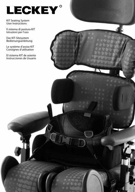
<strong>KIT</strong> <strong>Seating</strong> <strong>System</strong><br />
<strong>User</strong> <strong>Instructions</strong><br />
<strong>Il</strong> <strong>sistema</strong> <strong>di</strong> <strong>postura</strong> <strong>KIT</strong><br />
Istruzioni per l’uso<br />
Das <strong>KIT</strong>-Sitzsystem<br />
Be<strong>di</strong>enungsanleitung<br />
Le système d’assise <strong>KIT</strong><br />
Consignes d’utilisation<br />
El <strong>sistema</strong> <strong>KIT</strong> de asiento<br />
Instrucciones de Usuario
1. Intended Use<br />
The <strong>KIT</strong> <strong>Seating</strong> <strong>System</strong> is a seat that<br />
has been designed for use by adults<br />
and teenagers (from 12 years old) with<br />
<strong>di</strong>sabilities, in the home, in day centres,<br />
in schools and outdoors, if used on a<br />
mobility base. The seating system has a<br />
maximum user weight of 75kg (165lbs).<br />
The seating system is modular and can be<br />
used with a choice of indoor or outdoor<br />
chassis. The Hi-low chassis has been<br />
designed for indoor use but can also be<br />
used outdoors on an even surface. The<br />
Hi-low chassis should never be exposed<br />
to the elements as this may corrode the<br />
metal components.<br />
The Kit seat unit will interface with a<br />
range of mobility bases, the details of<br />
which can be found on our website,<br />
www.leckey.com.<br />
2. Declaration of Conformity<br />
James <strong>Leckey</strong> Design Ltd as manufacturer<br />
with sole responsibility declares that<br />
the Kit <strong>Seating</strong> <strong>System</strong> conforms to the<br />
requirements of the 93/42/EEC Guidelines,<br />
Me<strong>di</strong>cal Device Regulations 2002 and EN<br />
12182 Technical aids for <strong>di</strong>sabled persons<br />
and test methods.<br />
3. Terms of Warranty<br />
The warranty applies only when the<br />
product is used accor<strong>di</strong>ng to the<br />
specified con<strong>di</strong>tions and for the intended<br />
purposes, following all manufacturers’<br />
recommendations (also see general terms<br />
of sales, delivery and payment). A two<br />
year warranty is provided on all <strong>Leckey</strong><br />
manufactured products and components.<br />
4. Product History Record<br />
Your <strong>Leckey</strong> product is classified as a<br />
Class 1 Me<strong>di</strong>cal Device and as such<br />
should only be prescribed, set up or<br />
reissued by a technically competent<br />
person who has been trained in the use<br />
of this product. <strong>Leckey</strong> recommend that<br />
a written record is maintained to provide<br />
details of all set ups, reissue inspections<br />
and annual inspections of this product.<br />
5. Product Training Record<br />
(Parents, Teachers & Carers)<br />
Your <strong>Leckey</strong> product is classified as a<br />
Class 1 Me<strong>di</strong>cal Device and as such<br />
<strong>Leckey</strong> recommend that parents, teachers<br />
and carers using the equipment should<br />
be made aware of the following sections<br />
of this user manual by a technically<br />
competent person:<br />
Section 6<br />
Safety Information<br />
Section 8<br />
Clinical Set up for Postural Management<br />
Section 9<br />
Cleaning and Care<br />
Section 10<br />
Daily Product Inspection<br />
<strong>Leckey</strong> recommend that a written record<br />
is maintained of all those who have trained<br />
in the correct use of this product.
6 Safety Information<br />
6.1 Always read instructions fully before<br />
use.<br />
6.2 <strong>User</strong>s should not be left unattended at<br />
any time while using <strong>Leckey</strong> equipment.<br />
6.8 When the seat is in use on the Hi-low<br />
chassis we do not recommend that the<br />
users are moved over uneven surfaces<br />
when in the equipment. All due care<br />
and attention should be taken when<br />
transporting the user in and out of the seat.<br />
6.3 Only use <strong>Leckey</strong> approved components<br />
with your product. Never mo<strong>di</strong>fy the<br />
product in any way. Failure to follow<br />
instructions may put the user or carer<br />
at risk and will invalidate the warranty on<br />
the product.<br />
6.4 If in any doubt to the continued safe<br />
use of your product or if any parts should<br />
fail, please cease using the product and<br />
contact our customer services department<br />
or local dealer as soon as possible.<br />
6.5 Carry out all positional adjustments<br />
and ensure that they are securely fastened<br />
before you put the user into this product.<br />
Some adjustments may require the use of<br />
a tool which is provided with each product.<br />
Keep all tools out of reach of children.<br />
6.6 When placing the user into a seating<br />
system, for safety and positional reasons,<br />
always secure the Pelvic Cradle first.<br />
6.7 When the product is stationary ensure<br />
that all wheels are locked and facing away<br />
from the base as this will improve product<br />
stability. This is especially important<br />
when the tilt in space or back recline<br />
facility is in use.<br />
6.9 Never leave the product on a sloping<br />
surface, greater than 5 degrees. Always<br />
remember to lock all the wheels.<br />
6.10 Only use the push handles to steer<br />
and move the seat from one area to<br />
another. Never use the tray for this<br />
purpose.<br />
6.11 The product contains components<br />
which could present a choking hazard to<br />
small children. Always check that locking<br />
knobs and bolts within the user’s reach are<br />
tightened and secure at all times.<br />
6.12 <strong>Leckey</strong> products comply with fire<br />
safety regulations in accordance with<br />
EN12182. However the product contains<br />
plastic components and therefore should<br />
be kept away from all <strong>di</strong>rect sources of<br />
heat inclu<strong>di</strong>ng naked flames, cigarettes,<br />
electric and gas heaters.<br />
6.13 Do not place hot items greater than<br />
40º centigrade on the tray.<br />
6.14 Clean the product regularly. Do<br />
not use abrasive cleaners. Carry out<br />
maintenance checks on a regular basis to<br />
ensure your product is in good working<br />
con<strong>di</strong>tion.
<strong>KIT</strong> <strong>Seating</strong> <strong>System</strong> –<br />
Crash Test<br />
6.15 When the product is not in use, it<br />
should be stored in a dry place that is not<br />
subjected to extremes of temperature. The<br />
safe operating temperature range of the<br />
product is +5 to +40 degrees Celsius.<br />
The <strong>KIT</strong> <strong>Seating</strong> <strong>System</strong> has been crash<br />
tested and passed for use in vehicles.<br />
It has been tested in its complete<br />
configuration on a surrogate base with a<br />
<strong>Leckey</strong> head support attached.<br />
6.16 Always check the ratchet handles on<br />
the push handle are tightened securely<br />
before you move the seat unit.<br />
If the <strong>KIT</strong> <strong>Seating</strong> <strong>System</strong> is being used<br />
in a vehicle, the following points must be<br />
adhered to:<br />
6.17 Before using the seating system<br />
always check that the interface handle<br />
on the seat unit is fully engaged with the<br />
chassis and the locking pin is engaged.<br />
If the handle is not engaged properly, the<br />
seat unit may come loose and could cause<br />
serious injury to the user or carer.<br />
The <strong>KIT</strong> <strong>Seating</strong> <strong>System</strong> must be<br />
positioned forward facing and used<br />
with an Unwin Restraint <strong>System</strong> and a<br />
<strong>Leckey</strong> head support, which should be<br />
suitably positioned at all times during<br />
transportation. The head support is<br />
available as an optional accessory with<br />
the <strong>KIT</strong> <strong>Seating</strong> <strong>System</strong>.<br />
The <strong>KIT</strong> <strong>Seating</strong> <strong>System</strong> is crash tested<br />
and meets the requirements of ISO 16840<br />
part 4. The seat has also been tested and<br />
meets the requirements of ISO 7176-19.<br />
The crash tests were carried out using<br />
a chest harness and Pelvic Cradle.<br />
For further details please contact our<br />
Customer Service Department.<br />
Important<br />
If you are using the <strong>KIT</strong> <strong>Seating</strong> <strong>System</strong><br />
on a wheelchair base, please refer to the<br />
wheelchair manufacturer’s handbook for<br />
crash test details.
How to<br />
unpack and<br />
assemble<br />
the seating<br />
system and fit<br />
the cushions<br />
7
Check parts<br />
Congratulations on purchasing your <strong>KIT</strong><br />
<strong>Seating</strong> <strong>System</strong>. When opening the box,<br />
take care not to cut through the tape as<br />
you may damage some of the parts<br />
contained inside. All of the parts will be<br />
contained in polythene bags with each<br />
one clearly labelled. Carefully remove them<br />
from the boxes and check all the parts you<br />
have ordered.<br />
Safety First<br />
Keep polythene bags away from children.<br />
Some of the accessories will need to be<br />
assembled before you attach them to the<br />
seat base you have purchased. If you are<br />
fitting the seat to a mobility base, please<br />
ensure you fit the interface plate to the<br />
mobility base first. <strong>Instructions</strong> on how to<br />
attach the interface to specific bases will be<br />
provided with the interface plate. Once you<br />
have checked all the components you are<br />
ready to assemble the <strong>KIT</strong> <strong>Seating</strong> <strong>System</strong><br />
and attach it to its base. Please follow the<br />
order suggested as it is often easier to fit the<br />
cushions before assembling the hardware.<br />
Tools<br />
A number of the adjustments will require<br />
the use of the multi-tool, T-bar allen key or<br />
a 13mm spanner which are provided with<br />
each seat.
7.1 Attaching the <strong>Seating</strong><br />
<strong>System</strong> to the Hi-low Chassis<br />
Before attaching the seat unit to the base<br />
raise the height of the chassis to its maximum<br />
to reduce the risk of back strain.<br />
Release the safety locking pin at the front of<br />
the seat by pulling the pin (A) out and rotating<br />
it through 90 degrees. Carefully tilt the seat<br />
and place it onto the chassis, locating the<br />
channel (B) at the rear of the seat over the<br />
tube at the back of the chassis (C).<br />
Pull the handle (D) at the front of the seat<br />
unit up and then pivot the seat down.<br />
Once the seat is fully lowered, release the<br />
handle and push it forward to ensure it has<br />
fully engaged on the front tube. Rotate the<br />
safety locking pin (A) so that it engages in the<br />
front of the handle.<br />
Always check the handle and locking pin<br />
are fully engaged before you place the user<br />
in the seating system. If the handle is not<br />
engaged properly, the seat unit can come<br />
loose and could cause serious injury to the<br />
user or the carer.<br />
B<br />
C<br />
D<br />
A<br />
A
7.2 Removable<br />
Backrest spine<br />
The removable backrest spine will be<br />
detached for shipping. Insert it into the side<br />
plates of the seat base, slipping the front pin<br />
(A) into the front slot (B) on both sides of the<br />
seat base. Angle the spine back. Place the<br />
pin (C) through the base of the spine.<br />
A<br />
B<br />
B<br />
A<br />
C
7.3 Fixed Backrest<br />
spine<br />
7.4 Seat Base<br />
Cushion<br />
If the fixed backrest spine option has been<br />
ordered, simply rotate the backrest into the<br />
vertical position and insert pin (A) through the<br />
base of the spine.<br />
Fasten the two poppers (A) at the back of the<br />
seatbase. Press the cushion down onto the<br />
Velcro which is on the leg support ramps.<br />
Loop the elastic over the hooks (B) on the<br />
side of the seatbase.<br />
A<br />
A<br />
B
7.5 Sacral support<br />
7.6 Hip Laterals<br />
Fit the sacral cushion over the hardware and<br />
fasten at the back with the poppers. The<br />
standard sacral support should be attached<br />
with the double flaps (A) at the top.<br />
To attach the sacral support, slide the<br />
support onto the lowest mounting bracket on<br />
the backrest spine. Secure it with a bolt (B)<br />
on either side. Cover the bracket with a spine<br />
upholstery shroud (C).<br />
To attach the hip laterals to the standard<br />
sacral support, loosen the screw (A) and<br />
insert the bar of the hip lateral into the hole<br />
on the side of the sacral support. Tighten the<br />
screw to secure.<br />
To attach the hip lateral covers, slide the<br />
cover over the lateral support.<br />
A<br />
B<br />
A<br />
C
7.7 Contoured sacral<br />
support<br />
7.8 Thoracic Support<br />
To fit the contoured sacral support cushion,<br />
loosen the laterals using the screw (A) on the<br />
hinge. Insert laterals into pockets and fasten<br />
poppers on back.<br />
Slide the support onto the lowest mounting<br />
bracket on the backrest spine. Secure it with<br />
a bolt (B) on either side. Cover the bracket<br />
with a spine upholstery shroud (C).<br />
Fit the cushion over the hardware and fasten<br />
at the back with the poppers.<br />
Slide the support onto the middle mounting<br />
bracket on the backrest spine. Secure it with<br />
a bolt (A) on either side. Cover the bracket<br />
with a spine upholstery shroud (B).<br />
B<br />
A<br />
A<br />
C<br />
B
7.9 Standard and<br />
Complex Thoracic<br />
Laterals<br />
The standard and complex (horizontal and<br />
vertical) laterals are attached in the same<br />
way to the thoracic support. Before attaching<br />
laterals, remove the thoracic cushion.<br />
Before removing the bolt from the bracket<br />
components, make a note of the order in<br />
which the pieces fit together.<br />
While hol<strong>di</strong>ng the rest of the components<br />
together, remove the bolt and washer (A)<br />
with the Allen tool. Keeping the rest of the<br />
components together, place the plastic<br />
moul<strong>di</strong>ng into the slot (B). The bar should go<br />
into the recess of the thoracic support. Insert<br />
the bolt from the back and tighten. Fit the<br />
lateral covers.<br />
A<br />
B<br />
B
7.10 Angle<br />
Adjustable Thoracic<br />
Laterals<br />
The angle adjustable laterals are attached to<br />
the standard thoracic support. Position the<br />
lateral brackets over the slot in the thoracic<br />
supports and secure with two bolts (A).<br />
Fit the cushion cover over the hardware and<br />
secure with the poppers.<br />
7.11 Shoulder Support<br />
To fit the shoulder support cushion, loosen<br />
the laterals using the screw (A) on the hinge.<br />
Insert laterals into pockets and fasten poppers<br />
on back.<br />
Slide the support onto the top mounting<br />
bracket on the backrest spine. Secure it with<br />
a bolt (B) on either side. Cover the bracket<br />
with a spine upholstery shroud (C).<br />
A<br />
A<br />
B<br />
C
7.12 Pelvic Cradle<br />
7.13 Chest Pad<br />
Fasten the front buckle and side Velcro tabs of<br />
the Pelvic Cradle. Ensure the “Back” label (A)<br />
is against the backrest and the “Seat” label (B)<br />
is on the seatbase cushion. Stick the Velcro<br />
down to the seatbase cushion. Attach the four<br />
side release buckles (C), two at the back of the<br />
seatbase and two at the side.<br />
Screw the buckles onto the thoracic laterals.<br />
Attach the chest pad to the buckles (A).<br />
We recommend that lateral covers are always<br />
fitted when using the chest pad. To attach<br />
lateral covers, slide them over the lateral<br />
ensuring that the slot is on the outside to<br />
access the chest pad attachment buckle.<br />
A<br />
B<br />
A<br />
C
7.14 Chest Harness<br />
To attach the chest harness to the shoulder<br />
section, first remove the cushion and plastic<br />
cover. Feed the webbing into the holes (A) in<br />
the moul<strong>di</strong>ngs and fasten with the nuts and<br />
bolts provided. Attach the top straps to these<br />
buckles. The lower straps attach onto the<br />
buckles on the sacral support. If the standard<br />
sacral support is used, attach the webbing<br />
through the holes (B) at the top of the<br />
moul<strong>di</strong>ng and fasten with the nuts and bolts<br />
provided. If the contoured sacral cushion is<br />
used, attach the webbing through the holes<br />
(C) at the bottom of the moul<strong>di</strong>ng and fasten<br />
with the nuts and bolts provided.<br />
B<br />
C<br />
A
7.15 Headrest<br />
To attach the head support (<strong>Leckey</strong> or<br />
Otto Bock) slide the stem into the receiving<br />
bracket (A) and secure by tightening the<br />
screw (B).<br />
The <strong>KIT</strong> <strong>Seating</strong> <strong>System</strong> has been designed to<br />
interface with a range of other supports that<br />
require a box section receiving bracket. Insert<br />
the bracket box section into the top<br />
of the spine. Secure the head support onto<br />
this bracket.<br />
Box section bracket<br />
B<br />
A
A<br />
7.16 Femoral Gables 7.17 Foot Supports<br />
Femoral gables are attached to the seat base<br />
using bolts (A). There are two bolts for each<br />
gable. Bolts should be firmly secured.<br />
Loosen the leg support nuts (A) on the<br />
underside of the seat base with a spanner.<br />
Move the leg supports forward one at a<br />
time. This makes it easier to insert the foot<br />
supports. Open the screws (B) and slide in<br />
the foot supports from the centre. Retighten<br />
the screws. Reposition the leg supports and<br />
retighten nuts.<br />
Always make sure the foot supports are<br />
attached securely.<br />
A<br />
A<br />
B
A<br />
7.18 Attaching the<br />
Sandal Straps<br />
Sandal straps can be attached to the foot<br />
supports. Feed the back straps through the<br />
slots in the rear of the sandals. Remove the<br />
bolts on the underside of the sandals, thread<br />
the bolts (A) through the ends of the straps<br />
and refasten. The front straps are simply<br />
fed from below through the front slots on<br />
the sandals.<br />
A
7.19 Armrests<br />
7.20 Tray<br />
To attach the armrests, loosen the ratchet<br />
handles (A) and insert the armrests with<br />
the side with the adjustment knobs (B)<br />
facing outwards.<br />
Before attaching the tray, ensure the armrests<br />
are at the same height and angle. The tray<br />
is attached to the seat by inserting the tray<br />
tubes through the centre of the armrest.<br />
Tighten knob (A) to secure.<br />
B<br />
A<br />
A
7.21 Attaching the Foam<br />
Spacer Pads<br />
7.22 Setting up the<br />
Push Handle<br />
The foam spacer pads can be used to<br />
support an obliquity or under the thighs. They<br />
can be cut to size and attached using Velcro.<br />
Unfold the push handle until straight and<br />
secure in position with the spring popper (A)<br />
at either side.<br />
A<br />
A
7.23 Interfaces for<br />
wheelchair bases<br />
The set up and attachment of the <strong>KIT</strong><br />
seat to any mobility base should be<br />
completed by a technically competent<br />
person who is familiar with the set up of<br />
the mobility base.<br />
The <strong>Leckey</strong> Mobility Base is built with an<br />
interface which fits the <strong>KIT</strong> seat.<br />
45cm Discovery Interface attachment to<br />
18” (450mm) wide mobility base<br />
The <strong>KIT</strong> seat can be easily attached to the<br />
Discovery 45cm wide wheel base.<br />
Always refer to the mobility base<br />
manufacturer’s guidelines for correct set<br />
up, paying particular attention to product<br />
centre of gravity and stability.<br />
A thorough risk assessment should be<br />
carried out when attaching the <strong>KIT</strong> Seat to<br />
any mobility base not supplied by <strong>Leckey</strong>.<br />
Please refer to specific assembly instructions<br />
supplied with your interface for correct<br />
positioning of your base. The interface<br />
should be fitted by a qualified technician<br />
who is technically competent in the set up<br />
of the mobility base. The position of the<br />
push handles, leg hangers and armrests on<br />
the mobility base may need to be adjusted<br />
depen<strong>di</strong>ng on the size and weight of the user<br />
to ensure the stability of the seat.<br />
<strong>Leckey</strong> Mobility Base<br />
45cm Discovery Base
Clinical<br />
Set up for<br />
Postural<br />
Management<br />
The clinical set up of the product should<br />
be completed by a technically and clinically<br />
competent person who has been trained in<br />
the use of the product. <strong>Leckey</strong> recommend<br />
a written record is kept of all clinical set<br />
ups for this product.<br />
<strong>Leckey</strong> recommend that a full supine lying<br />
and unsupported sitting assessment is<br />
carried out prior to setting up the product.<br />
Set the height and angle of each backrest<br />
section (A), the seat depth (B) and the foot<br />
support height (C) before placing the user<br />
in the seat. These can be fine tuned when<br />
the user is in the seat.<br />
C<br />
B<br />
A<br />
8
8.1 Backrest angle 8.2 Backrest Height<br />
To change the angle loosen the screw (A) at<br />
the bottom of the backrest spine, adjust to<br />
the required position and retighten the screw<br />
securely.<br />
The backrest angle can be adjusted with the<br />
user in the seat.<br />
Hold the backrest spine with one hand<br />
while you adjust the back angle.<br />
To adjust the overall height of the backrest<br />
loosen the screw (A), adjust the shoulder<br />
section to the required position and retighten<br />
the screw securely. The height can be fine<br />
tuned with the user in the seat.<br />
Use caution when adjusting to minimum<br />
setting as fingers could become trapped<br />
between moving and static parts.<br />
A<br />
A<br />
A
8.3 Pelvic Cradle 8.4 Gluteal ramp<br />
When setting up the Pelvic Cradle for the first<br />
time with the client in it, the Pelvic Cradle<br />
should be flat and open before the user is<br />
placed into the Kit <strong>Seating</strong> <strong>System</strong>. All four<br />
side and back buckles should be already<br />
attached to the seat. When the client is placed<br />
in the seat, first fasten the buckle (A) at the<br />
front of the Pelvic Cradle. Then fasten the<br />
Velcro (B) at the sides to fit the Pelvic Cradle<br />
to the user. Then adjust the front and rear<br />
straps (C) and (D) to secure to position the<br />
user’s pelvis.<br />
If a gluteal ramp (A) is required, it can be<br />
attached by Velcro to the front of the<br />
Pelvic Cradle before the user is placed into<br />
the seat.<br />
After initial set up, only the front<br />
buckle (A) needs to be released when<br />
the user is transferred in or out of the <strong>KIT</strong><br />
<strong>Seating</strong> <strong>System</strong>.<br />
Once a week, check that the Pelvic Cradle<br />
has not become slack.<br />
B<br />
D<br />
B<br />
A<br />
A<br />
C
8.5 Sacral Support<br />
The sacral support can be adjusted in a<br />
number of ways - height, depth and angle.<br />
To adjust the height or the depth, remove the<br />
spine upholstery shroud and loosen the two<br />
screws (A) on either side of the bracket. Move<br />
the sacral support to the required position,<br />
height and depth. Retighten the screws and<br />
replace the spine upholstery shroud.<br />
To adjust the angle of the sacral support,<br />
loosen both the screws (B) on the ball and<br />
socket joint. Position the support at the<br />
required angle. Retighten the screws.<br />
B<br />
B<br />
A
A<br />
8.6 Hip Laterals<br />
The hip laterals can be width and angle<br />
adjusted to suit the user’s requirements.<br />
Loosen the screws (A) at the back of the<br />
sacral support. Move the hip laterals to<br />
required position. Ideally the hip laterals<br />
should always be rotated so they rest on top<br />
of the seat cushion even if the backrest or<br />
sacral support is angled. Once the hip laterals<br />
are in position, retighten the screws securely.<br />
The laterals can also be angled to<br />
help support abduction, adduction or<br />
windsweeping.<br />
To adjust the angle of the hip laterals loosen<br />
the screw (B) on the hinge of the hip lateral.<br />
Adjust to the required angle. Retighten the<br />
screw. The pads can also be adjusted in<br />
depth and a small degree of rotation by<br />
loosening the screws (C) on the pad, sli<strong>di</strong>ng it<br />
to the required position and retightening the<br />
screws.<br />
C<br />
A<br />
B<br />
B<br />
C
8.7 Contoured Sacral<br />
Support<br />
The contoured sacral support can be<br />
adjusted in a number of ways - height, depth<br />
and angle.<br />
To adjust the height or the depth, remove the<br />
spine upholstery shroud and loosen the two<br />
screws (A) on either side of the bracket. Move<br />
the sacral support to the required position.<br />
Retighten the screws and replace the spine<br />
upholstery shroud.<br />
The lateral supports can be angle adjusted<br />
to contour the pad and provide lateral pelvic<br />
support. To angle, loosen screw C, set to<br />
required angle and retighten securely.<br />
To adjust the angle of the sacral support,<br />
loosen both the screws (B) on the ball and<br />
socket joint. Position the support at the<br />
required angle. Retighten the screws.<br />
B<br />
B<br />
C<br />
C<br />
A
8.8. Thoracic Support<br />
The thoracic support can be adjusted in<br />
a number of ways: height, lateral position<br />
and angle.<br />
To adjust the height, remove the spine<br />
upholstery shroud, loosen the two screws (A)<br />
on either side of the mounting bracket, slide<br />
to the required position and then retighten<br />
the screws securely.<br />
To adjust the thoracic support laterally or in<br />
angle, loosen both the screws (B) on the ball<br />
and socket joint, position the support at the<br />
required angle or lateral position and then<br />
retighten the screws securely.<br />
B<br />
B<br />
A
8.9 Standard and Complex<br />
Thoracic Laterals<br />
The standard and complex laterals, horizontal<br />
and vertical options can be used in whatever<br />
combination is most suited to the user’s<br />
requirements. It is possible to attach more<br />
than one lateral to the same side of the<br />
thoracic support if required.<br />
To adjust the height, width or angle of these<br />
laterals, loosen the screw (A) on the lateral<br />
mounting. Position the lateral at the required<br />
height, width and angle. Retighten the screw.<br />
The complex laterals can also be angled to<br />
allow the pad to contour to the user’s shape.<br />
To adjust loosen the screw (B) at the centre<br />
of the pad, angle the pad to the required<br />
position and retighten the screw.<br />
All of the laterals can be flipped away to aid<br />
transfer, by pulling the pin (C) at the back and<br />
rotating the support out of the way.<br />
B<br />
A<br />
A<br />
C
8.10 Angle Adjustable<br />
Thoracic Laterals<br />
8.11 Shoulder Support<br />
To adjust the angle of the laterals, loosen the<br />
screws (A) at the hinges. Contour the laterals<br />
to the required angle. Retighten the screws.<br />
The laterals have a small degree of depth<br />
and rotational adjustment for more proximal<br />
positioning. Loosen screws (B) adjust the pad<br />
and retighten the screws securely.<br />
The shoulder support can be adjusted<br />
in a number of ways – height, depth<br />
and angle.<br />
To adjust the height or the depth, remove<br />
the spine upholstery shroud, loosen the two<br />
screws (A) on either side of the mounting<br />
bracket. Move the shoulder support to the<br />
required position. Retighten the screws and<br />
replace the spine upholstery shroud.<br />
If further height adjustment is required, please<br />
refer to the section on Backrest Height.<br />
The Size 2 shoulder support can also be<br />
attached to the Size 1 seat to further increase<br />
the backrest height.<br />
B<br />
A<br />
B<br />
A
To adjust the angle of the whole shoulder<br />
support, loosen both the screws (B) on the<br />
ball and socket joint. Position the support at<br />
the required angle. Retighten the screws.<br />
To adjust the angle of the wings of the<br />
shoulder support, loosen both the screws (C)<br />
at the hinges. Contour the shoulder support to<br />
the required shape. Retighten the screws.<br />
B<br />
B<br />
C
8.12 Headrest 8.13 Seat Base Depth<br />
To adjust the height of the headrest, loosen<br />
the screw (A) at the top of the backrest spine.<br />
Position the headrest to the required<br />
height to suit the user’s head position.<br />
Retighten the screw.<br />
To position the headrest, loosen one or both<br />
of the plastic handles (B) at the hinges of the<br />
headrest mounting. Position the headrest as<br />
required. Retighten the screws.<br />
To adjust the seat base depth, loosen the nuts<br />
(A) underneath the upper leg supports with a<br />
spanner. Move the upper leg support in or out<br />
to the required position and retighten the nuts<br />
securely. It is possible to upgrade the Size 1<br />
seat base to achieve the same seat depth size<br />
as the Size 2 seat.<br />
To angle or rotate the head support, loosen<br />
screws (C), set to required position and<br />
retighten securely.<br />
To change the profile of the Profiling<br />
Contoured Headrest, remove the cover,<br />
loosen the screws (D), set to the required<br />
position and retighten screws. Fit the<br />
cover again.<br />
C<br />
B<br />
A<br />
A<br />
A<br />
D
8.14 Seat base – Upper Leg Support Angle for<br />
Windsweeping, Abduction or Adduction<br />
To adjust the upper leg support angle<br />
loosen the nuts (A) underneath the upper leg<br />
supports, adjust to the required angle and<br />
then retighten the nuts securely.<br />
A<br />
A
8.15 Femoral Gables 8.16 Foot support height<br />
Large and small femoral gables may be<br />
used in any combination to suit the user’s<br />
requirements, or they may be removed<br />
altogether. To adjust the angle or width of<br />
the femoral gables, loosen the screws (A) and<br />
position as required. Retighten the screws.<br />
There are two screws per femoral gable.<br />
To raise or lower the height of the foot<br />
support, loosen the screw (A) adjust to the<br />
required position and retighten the screw<br />
securely.<br />
A<br />
A
8.17 Calf Support 8.18 Foot support - size<br />
To adjust the calf support angle, loosen the<br />
screw (A) at the top of the calf support, move<br />
front or back to the required angle, then<br />
retighten screw.<br />
To change the size of the foot supports to<br />
accommodate <strong>di</strong>fferent shoe sizes, loosen the<br />
screws (A) at the toes of the foot supports.<br />
Adjust the foot support to the required size.<br />
Retighten the screws.<br />
Note: A 5mm tool is required.<br />
A<br />
A
8.19 Foot support - angle<br />
(Complex supports only)<br />
To change the angle of the foot supports,<br />
loosen the three screws (A) on the ball and<br />
socket joint on the underside of the foot<br />
support. Change the angle to suit the user’s<br />
requirements. Retighten the screws.<br />
Note: A 5mm tool is required.<br />
To flip away the foot supports, pull out the<br />
pin (B) at the back of the sandals and rotate<br />
it through 90°. Hol<strong>di</strong>ng your thumb on C,<br />
slide the foot support outwards, away from<br />
the centre line, then flip up. The foot support<br />
locks in the vertical position.<br />
C<br />
B<br />
C<br />
B<br />
A<br />
C<br />
B<br />
C
8.20 Armrest<br />
8.21 Tilt in Space<br />
To adjust the armrest height, loosen the knob<br />
(A), adjust to the required height and retighten<br />
the knob. To adjust the angle pull the pin (B)<br />
out and rotate the armrest to the required<br />
position, then release the pin ensuring the pin<br />
is securely located in one of the holes.<br />
Armrest pads can be moved forwards<br />
or backwards by removing screws (C),<br />
repositioning the armrest pad and reattaching<br />
securely in position with the screws.<br />
The tilt in space can be angled when the<br />
user is in the seat. Before you adjust the tilt<br />
in space angle of the seat always ensure that<br />
the Pelvic Cradle is secured, preventing the<br />
user from sli<strong>di</strong>ng forwards in the seat.<br />
To adjust the tilt angle, pull the lever on the<br />
push handles, tilt the seat to the required<br />
angle and remove your hand from the lever.<br />
Always hold push handles securely before<br />
using the tilt in space lever.<br />
C<br />
A<br />
B
8.22 Hi-low Chassis –<br />
Height Adjustment<br />
You can carry out this adjustment with the<br />
user in the chair. If your chassis has the foot<br />
pedal locking pin (A), <strong>di</strong>sengage it first. To<br />
unlock, pull the pin out and rotate through 90<br />
degrees. To adjust the height of the hydraulic<br />
Hi-low chassis press the foot lever (B) at the<br />
rear of the chassis. Once you remove your<br />
foot from the pedal, the seat will be fixed at<br />
this height. To lower the height place foot<br />
under the pedal and lift up, the seat height will<br />
gradually lower.<br />
For safety always engage the pull pin (A)<br />
after adjustment, if applicable.<br />
To adjust the height of the powered base,<br />
use the buttons on the handset. Before<br />
the product is used for the first time, it is<br />
recommended that the battery is fully charged<br />
for 12 hours. To do this, plug the adaptor<br />
into the mains socket and attach the lead<br />
to the battery. Switch on the mains power<br />
supply. When charged, switch off the mains<br />
power supply, remove the adaptor plug and<br />
<strong>di</strong>sconnect the lead from the battery. The<br />
battery charge should be topped up each<br />
day until the green light on the charge is<br />
illuminated. The chair can be adjusted while<br />
attached to the mains.<br />
Ensure that the product and user are<br />
away from surroun<strong>di</strong>ng furnishings when<br />
adjusting the height to prevent possible<br />
collisions and injury to the user or damage<br />
to the product.<br />
A<br />
B
9 Cleaning & Care<br />
Information<br />
How to Maintain<br />
When cleaning the product we recommend<br />
that you use only warm water and a<br />
nonabrasive detergent. Never use organic<br />
solvents or dry cleaning fluids.<br />
Upholstery and fabrics<br />
1. The upholstery and fabrics can be<br />
removed and machine washed and tumble<br />
dried at a low setting. The standard covers<br />
can be washed at 40ºC and the Infection<br />
Control covers at 90ºC. Please remove the<br />
foam before washing the following covers:<br />
Metal and plastic components<br />
1. Soap and water or antibacterial spray can<br />
be used for daily cleaning.<br />
2. For deep cleaning a low pressure steam<br />
cleaner can be used.<br />
3. Do not use solvents to clean plastic or<br />
metal components.<br />
4. Make sure the product is dry before use.<br />
Shoulder support<br />
Thoracic support<br />
Sacral support<br />
Contoured sacral support<br />
Seat base.<br />
All other soft upholstery can be placed<br />
<strong>di</strong>rectly in the washing machine. Use a wash<br />
bag to prevent covers being damaged in the<br />
washing machine.<br />
2. If the upholstery is to be cleaned in-situ,<br />
the best cleaning method is a ‘wipe & dry’<br />
technique.<br />
3. Staining should be removed as quickly<br />
as possible with absorbent cloth, towels or<br />
a sponge. Routine soap and warm water<br />
sponging is effective for or<strong>di</strong>nary soiling and<br />
minor spills. Be careful not to over wet the<br />
fabric, as this will cause the staining<br />
to spread.<br />
4. Always ensure the product is dry<br />
before use.
10 Daily Product Inspection<br />
11 Annual Product<br />
Inspection<br />
(Therapists, parents & carers)<br />
We recommend that daily visual checks of<br />
the equipment are carried out by therapists,<br />
carers or parents to ensure the product is<br />
safe for use. The recommended daily checks<br />
are detailed below.<br />
Seat Checks<br />
1. Ensure all adjustment knobs and bolts<br />
are in place and secure.<br />
2. Check all upholstery for signs of wear<br />
and tear.<br />
3. Check all Velcro strips and brush fluff to<br />
ensure straps secure firmly.<br />
4. Check all back support components<br />
are secure.<br />
Chassis Checks<br />
1. Check all wheels are moving freely and<br />
lock securely.<br />
2. Check height adjustment is working and<br />
pedal is locking.<br />
3. Check tilt in space is working and<br />
locking securely.<br />
4. Check locking pin on the interface handle<br />
is in its locked position.<br />
If in any doubt to the continued safe<br />
use of your <strong>Leckey</strong> product or if any<br />
parts should fail, please cease using the<br />
product and contact our customer service<br />
department or your local dealer as soon<br />
as possible.<br />
(Therapist, Technician, <strong>Leckey</strong> Product<br />
Advisor, Dealer)<br />
<strong>Leckey</strong> recommend that each product should<br />
be subject to a detailed inspection at least<br />
once a year and every time the product is<br />
reissued for use. This inspection should<br />
be carried out by a technically competent<br />
person who has been trained in the use of<br />
the product and should include the following<br />
checks as a minimum requirement.<br />
1. Check all knobs, nuts, bolts and plastic<br />
buckles are in place, replacing any missing<br />
items. Paying particular attention to the<br />
following items;<br />
- Buckles and Velcro on Pelvic Cradle<br />
- Seat interface handle locks and releases<br />
- Tilt in space and height adjustment work<br />
and lock securely<br />
- All ball and socket joints lock securely,<br />
shoulder, thoracic, sacral and foot supports<br />
- Backrest angle adjusts and locks securely<br />
- Leg supports angle adjust and<br />
lock securely<br />
- Armrest height and angle adjust and<br />
lock securely<br />
- Head support locks securely<br />
2. Lift the base to check each wheel<br />
in<strong>di</strong>vidually. Make sure they are moving<br />
freely and remove any <strong>di</strong>rt from the rubber<br />
wheels. Check that the brakes lock the<br />
wheels securely.
12 Re-issuing <strong>Leckey</strong><br />
Products<br />
3. Visually check the structure of the product<br />
paying attention to weld points on the frame<br />
ensuring there are no signs of fatigue or<br />
cracking around the welds.<br />
4. <strong>Leckey</strong> recommend that a written record is<br />
maintained of all annual product inspections.<br />
If in any doubt to the continued safe<br />
use of your <strong>Leckey</strong> product or if any<br />
parts should fail, please cease using the<br />
product and contact our customer<br />
service department or your local dealer<br />
as soon as possible.<br />
Most <strong>Leckey</strong> products are assessed and<br />
ordered to meet the needs of an in<strong>di</strong>vidual<br />
user. Before reissuing a product we<br />
recommend that the therapist prescribing<br />
the product has carried out an equipment<br />
compatibility check for the new user and<br />
has ensured that the product being<br />
re-issued contains no mo<strong>di</strong>fications or<br />
special attachments.<br />
A detailed technical inspection should be<br />
carried on the product prior to re-issuing.<br />
This should be carried out by a technically<br />
competent person who has been trained in<br />
the use and inspection of the product.<br />
Please refer to section 11 for the required<br />
checks to be carried out.<br />
Ensure the product has been cleaned<br />
thoroughly in accordance with section 9<br />
of this manual.<br />
Ensure a copy of the user manual is supplied<br />
with the product. A copy can be downloaded<br />
from our website www.leckey.com.<br />
<strong>Leckey</strong> recommend that a written record is<br />
maintained of all product inspections carried<br />
out during the reissue of the product.<br />
If in any doubt to the continued safe<br />
use of your <strong>Leckey</strong> product or if any<br />
parts should fail, please cease using the<br />
product and contact our customer service<br />
department or your local dealer as soon<br />
as possible.
13 Product Servicing<br />
14 Technical<br />
Information<br />
Servicing of all <strong>Leckey</strong> products should only<br />
be carried out by technically competent<br />
persons who have been trained in the use of<br />
the product.<br />
In the UK & ROI please contact the <strong>Leckey</strong><br />
Service Centre on UK 0800 318265 or ROI<br />
1800 626020 and our customer service<br />
department will be delighted to assist you<br />
with your servicing requirements.<br />
All international service enquiries should be<br />
<strong>di</strong>rected to the appropriate <strong>Leckey</strong> <strong>di</strong>stributor<br />
who will be delighted to assist you. For<br />
further information on <strong>Leckey</strong> <strong>di</strong>stributors<br />
please visit our website www.leckey.com.<br />
Product and Accessory Codes<br />
133-1600-FIX Size 1 seat shell assembly<br />
with fixed backrest spine<br />
133-1600-REM Size 1 seat shell assembly<br />
with removable backrest spine<br />
139-2600-FIX Size 2 seat shell assembly<br />
with fixed backrest spine<br />
139-2600-REM Size 2 seat shell assembly<br />
with removable backrest spine<br />
133-404* Size 1 castellated foam seat<br />
base cushion and cover<br />
139-404* Size 2 castellated foam seat<br />
base cushion and cover<br />
133-405* Size 1 memory foam seat<br />
base cushion and cover<br />
139-405* Size 2 memory foam seat<br />
base cushion and cover<br />
133-611 Size 1 shoulder support<br />
assembly<br />
139-611 Size 2 shoulder support<br />
assembly<br />
133-400* Size 1 shoulder support<br />
cushion and cover<br />
139-400* Size 2 shoulder support<br />
cushion and cover<br />
133-605 Thoracic support assembly<br />
133-401* Thoracic cushion and cover<br />
133-619 Angle adjustable thoracic<br />
laterals hardware<br />
133-402* Angle adjustable thoracic<br />
cushion and cover<br />
133-612 Sacral support assembly<br />
133-403* Sacral support cushion and<br />
cover<br />
133-604 Size 1 contoured sacral<br />
support<br />
133-400* Size 1 contoured sacral<br />
support cushion and cover<br />
For product codes marked with *, please add<br />
the following colour option codes:<br />
+10 Blue +11 Grey<br />
+12 Purple +13 Grey Infection Control
Chassis<br />
133-750 Kit Hi-low base – hydraulic<br />
133-760 Kit Hi-low base – powered<br />
133-770 <strong>Leckey</strong> Mobility base<br />
133-740 45cm Discovery base and<br />
mobility interface<br />
Mobility Interface Options<br />
139-726 45mm Discovery interface A<br />
Accessories<br />
133-728 Pelvic Cradle Size 0<br />
133-729 Pelvic Cradle Size 1<br />
133-730 Pelvic Cradle Size 2<br />
133-731 Pelvic Cradle Size 3<br />
133-608 Hip lateral pads (pair)<br />
133-737 Pelvic Cradle gluteal ramp<br />
133-609 Flip away laterals (single<br />
without covers)<br />
133-747 Lateral covers (single)<br />
133-622-LH Flip away complex laterals –<br />
horizontal, left (single with<br />
covers)<br />
133-622-RH Flip away complex laterals –<br />
horizontal, right (single with<br />
covers)<br />
133-614-LH Flip away complex laterals –<br />
vertical, left (single with covers)<br />
133-614-RH Flip away complex laterals –<br />
vertical, right (single with<br />
covers)<br />
133-625 Chest pad<br />
133-1626 Chest harness Size 1<br />
133-2626 Chest harness Size 2<br />
133-3626 Chest harness Size 3<br />
133-627 Profiling contoured headrest<br />
133-716 Profiling contoured headrest<br />
cover<br />
133-626 PU contoured headrest<br />
133-735 Armrests (pair)<br />
133-635 Tray – clear<br />
133-624 Tray – black<br />
133-680 Padded tray insert<br />
133-721 Leg straps (pair)<br />
133-601 Femoral Gable Pack<br />
(2 large and 2 small)<br />
133-682 Large femoral gables – right<br />
133-686 Large femoral gables – left<br />
133-683 Small femoral gables – right<br />
133-687 Small femoral gables – left<br />
133-1005 Foam spacer pack (for obliquity)<br />
133-606 Foot supports – ball and socket<br />
joints (pair)<br />
133-607 Foot supports – basic (pair)<br />
133-712 Sandal straps size 1<br />
133-742 Sandal straps size 2<br />
133-765 Spine upholstery shroud (set)<br />
133-726 Lateral / bracket protector<br />
covers (single)<br />
133-749 Whitmyer bracket<br />
133-745 Head Support bracket for 1/2”<br />
and 15mm Box Section<br />
WASH01 Washing machine bag
<strong>KIT</strong> seat <strong>di</strong>mensions<br />
Product sizing Size 1 Size 2<br />
mm inches mm inches<br />
Age range 12-18 yrs 16-adult<br />
Stature range<br />
Min 1400 55.1 1600 63.0<br />
Max 1650 65.0 1850 73.0<br />
Max user weight (kg/lbs) 75 165.0 75 165.0<br />
Seat depth<br />
Min 360 14.2 410 16.1<br />
Max 480 18.9 560 22.0<br />
Max windsweep accommodation 20° 20° 20° 20°<br />
Max seat width - without laterals 430 16.9 430 16.9<br />
Seat width - with hip laterals<br />
Min 215 8.5 215 8.5<br />
Max 370 14.6 370 14.6<br />
Backrest height<br />
Min 500 19.7 560 22.0<br />
Max 620 24.4 675 26.6<br />
Shoulder width<br />
Min 190 7.5 260 10.2<br />
Max 500 19.7 600 23.6<br />
Chest width<br />
Min 230 9.1 230 9.1<br />
Max 380 15.0 380 15.0<br />
Backrest angle 90°-120° 90°-120° 90°-120° 90°-120°<br />
Seat to footplate<br />
Min 330 13.0 330 13.0<br />
Max 510 20.1 510 20.1<br />
Armrest height<br />
Min 265 10.4 265 10.4<br />
Max 380 15.0 380 15.0<br />
Tray size 630 x 460 24.8 X 18.1 630 X 460 24.8 X 18.1<br />
Seat weight (seat & back) 20.5 Kg 45.1 Lbs 21 kg 46.2 Lbs
<strong>Leckey</strong> Hi Low base options<br />
<strong>KIT</strong> Hi-low chassis<br />
mm<br />
inches<br />
Top of seat to floor<br />
Min 460 18<br />
Max 640 25<br />
With handle folded down<br />
Length 700 27.6<br />
Width 620 24.4<br />
Height 410 16<br />
LINAK Actuator specification<br />
- 281209-01<br />
Rated IP51<br />
Duty Cycle Max 10% or 2 min continuous use<br />
followed by 18 min not in use.<br />
Ambient temp +5deg to +40deg C<br />
Ambient Operating temp 22deg<br />
Storage temp -40deg C to 70degC<br />
Push Max 3500N<br />
Pull Max 2000N<br />
Self Lock at 3500N Push – 2000N Pull<br />
Typical speed with full load 4.7mm/sec<br />
Max amps at load of 3500N is 3.9 amps<br />
Noise level dB(A) 48<br />
Power input voltage 24v +- 10%<br />
LINAK Battery Box - BA18021-00<br />
Rated IP51<br />
Ambient temp +5deg to 40deg C<br />
Storage temp -20deg C to 60deg C<br />
Rated Capacity 1.2 Ah 24v<br />
Charging current is max 0.3A<br />
Lead acid gel filled battery<br />
LINAK Handset - HB41000-00004<br />
Rated IP51<br />
Control current 100mA per channel (Max)<br />
Ambient temp +5deg to +40deg C<br />
LINAK Battery Charger - CH01<br />
Mains 100-240 VAC/50-60 Hz switch mode<br />
power supply<br />
Charging voltage 27.6 VDC +- 2%<br />
Charging current Max 500mA<br />
Green LED for power on<br />
Yellow LED for charging function<br />
Yellow LED turns into green when batteries are<br />
fully charged.<br />
LINAK products may be stored in non-heated<br />
storage facilities with humi<strong>di</strong>ty between<br />
0 and 100%, none condensing. None condensing<br />
means that one should not take a product from<br />
an ice cold warehouse into<br />
a room with a temperature of 20deg C;<br />
if this is done then moistness will appear<br />
on the products.
1. Destinazione d’uso<br />
<strong>Il</strong> <strong>sistema</strong> <strong>di</strong> <strong>postura</strong> <strong>KIT</strong> è stato progettato<br />
per essere utilizzato da adulti e ragazzi<br />
<strong>di</strong>versamente abili dai 12 anni in su, a<br />
casa, nei centri <strong>di</strong>urni, a scuola e all’aperto<br />
se abbinato a una base per esterni. <strong>Il</strong><br />
<strong>sistema</strong> <strong>di</strong> <strong>postura</strong> può sostenere un peso<br />
massimo <strong>di</strong> 75 kg. <strong>Il</strong> <strong>sistema</strong> <strong>di</strong> <strong>postura</strong><br />
è modulare e può essere utilizzato con<br />
basi da interni e da esterni. La base<br />
Hi-low progettata per l’uso in interni,<br />
può essere utilizzata anche in esterni<br />
su superfici piane. La base Hi-low non<br />
dovrebbe essere esposta alle intemperie<br />
dal momento che i componenti in metallo<br />
si potrebbero corrodere.<br />
<strong>Il</strong> <strong>sistema</strong> <strong>di</strong> <strong>postura</strong> <strong>KIT</strong> può essere<br />
montato su <strong>di</strong>versi tipi <strong>di</strong> basi. Per<br />
maggiori informazioni visitate il nostro sito<br />
www.leckey.com.<br />
2. Dichiarazione <strong>di</strong> Conformità<br />
<strong>Il</strong> produttore, James <strong>Leckey</strong> Design Ltd,<br />
<strong>di</strong>chiara, sotto la propria responsabilità,<br />
che il <strong>sistema</strong> <strong>di</strong> <strong>postura</strong> <strong>KIT</strong> è conforme<br />
ai requisiti della <strong>di</strong>rettiva 93/42/CEE, del<br />
Regolamento sui Dispositivi Me<strong>di</strong>ci del<br />
2002 e della norma EN 12182 — Ausili<br />
tecnici per persone <strong>di</strong>sabili e meto<strong>di</strong> <strong>di</strong><br />
prova.<br />
3. Termini <strong>di</strong> Garanzia<br />
La garanzia si applica solo se il<br />
prodotto viene utilizzato in conformità<br />
con le con<strong>di</strong>zioni specificate e la sua<br />
destinazione d’uso, rispettando tutte le<br />
raccomandazioni del produttore (si vedano<br />
anche le con<strong>di</strong>zioni generali <strong>di</strong> ven<strong>di</strong>ta,<br />
consegna e pagamento).<br />
Tutti i prodotti e i componenti <strong>Leckey</strong><br />
sono garantiti due anni.<br />
4. Documentazione sulla storia<br />
del prodotto<br />
<strong>Il</strong> vostro prodotto <strong>Leckey</strong> è un <strong>di</strong>spositivo<br />
me<strong>di</strong>co <strong>di</strong> Classe 1 e, in quanto tale,<br />
dovrebbe essere prescritto e fornito<br />
pronto per l’uso, da personale tecnico<br />
competente, e formato sull’uso <strong>di</strong> questo<br />
prodotto.<br />
<strong>Leckey</strong> consiglia <strong>di</strong> conservare una<br />
documentazione scritta con le<br />
informazioni relative alle configurazioni, ed<br />
ai controlli annuali effettuati sul prodotto.<br />
5. Documentazione relativa alla<br />
formazione sull’uso del prodotto<br />
(genitori, insegnanti e assistenti)<br />
<strong>Il</strong> vostro prodotto <strong>Leckey</strong> è un <strong>di</strong>spositivo<br />
me<strong>di</strong>co <strong>di</strong> Classe 1 e, in quanto tale,<br />
<strong>Leckey</strong> raccomanda che genitori, insegnati<br />
e assistenti che utilizzano questo ausilio<br />
siano messi a conoscenza da personale<br />
tecnico competente delle seguenti sezioni<br />
del presente manuale:<br />
Sezione 6<br />
Informazioni sulla sicurezza<br />
Sezione 8<br />
Regolazioni ed aggiustamenti <strong>postura</strong>li<br />
Sezione 9<br />
Informazioni sulla pulizia e sulla<br />
manutenzione<br />
Sezione 10<br />
Controllo quoti<strong>di</strong>ano del prodotto<br />
<strong>Leckey</strong> consiglia <strong>di</strong> conservare la<br />
documentazione scritta riguardante<br />
tutti coloro che si sono occupati della<br />
formazione per l’uso corretto del prodotto.
6 Informazioni sulla sicurezza<br />
6.1 Prima dell’uso leggere con attenzione<br />
le istruzioni.<br />
6.2 Non lasciare mai soli gli utenti, mentre<br />
si usano le attrezzature <strong>Leckey</strong>.<br />
6.3 Applicare al prodotto solamente<br />
componenti approvati da <strong>Leckey</strong>. Non<br />
apportare mo<strong>di</strong>fiche al prodotto in nessun<br />
modo. La mancata osservanza delle<br />
istruzioni potrebbe mettere in pericolo<br />
l’utente o l’assistente e annullare la<br />
garanzia sul prodotto.<br />
6.4 In caso <strong>di</strong> dubbi sulla sicurezza del<br />
prodotto o sull’integrità <strong>di</strong> qualsiasi<br />
componente, si raccomanda <strong>di</strong><br />
interrompere l’uso del <strong>di</strong>spositivo e<br />
contattare il nostro customer service o il<br />
riven<strong>di</strong>tore locale il prima possibile.<br />
6.5 Regolare il <strong>sistema</strong> in tutte le<br />
posizioni e assicurarsi che siano tutte<br />
adeguatamente fissate prima <strong>di</strong> far<br />
sedere l’utente. Per alcune regolazioni<br />
potrebbe essere necessario utilizzare la<br />
chiave multiuso che viene fornita con ogni<br />
prodotto. Tenere tutti gli strumenti fuori<br />
dalla portata dei bambini.<br />
6.6 Per ragioni <strong>di</strong> sicurezza ed efficacia,<br />
prima <strong>di</strong> <strong>postura</strong>re l’utente sul <strong>sistema</strong>,<br />
“assicurare” l’imbragatura pelvica<br />
avvolgente “cradle”.<br />
6.7 Quando il <strong>sistema</strong> è fermo, al fine <strong>di</strong><br />
aumentare la stabilità, assicurarsi che<br />
tutte le ruote siano bloccate e rivolte in<br />
<strong>di</strong>rezione opposta alla base. Questo è<br />
particolarmente importante quando si<br />
utilizzano basculla il <strong>sistema</strong> o si reclina lo<br />
schienale.<br />
6.8 E’ sconsigliato il trasporto dell’utente<br />
sul <strong>sistema</strong> montato su base Hi-low, in<br />
percorsi irregolari. Si raccomanda la<br />
massima attenzione durante i trasferimenti<br />
dell’utente sul/dal <strong>sistema</strong> <strong>di</strong> <strong>postura</strong>.<br />
6.9 Non lasciare mai il <strong>di</strong>spositivo su<br />
superfici con pendenza maggiore <strong>di</strong> 5<br />
gra<strong>di</strong>. Ricordare sempre <strong>di</strong> bloccare tutte<br />
le ruote.<br />
6.10 Utilizzare solo le maniglie <strong>di</strong> spinta<br />
per spostare il <strong>sistema</strong> <strong>di</strong> <strong>postura</strong> da una<br />
zona all’altra. Non utilizzare mai il tavolino<br />
a questo scopo.<br />
6.11 <strong>Il</strong> prodotto contiene componenti<br />
che potrebbero costituire rischio <strong>di</strong><br />
soffocamento per i bambini. Controllare<br />
sempre che le manopole e i bulloni <strong>di</strong><br />
bloccaggio siano bloccati e ben sal<strong>di</strong>.<br />
6.12 I prodotti <strong>Leckey</strong> sono conformi<br />
al regolamento sulla sicurezza contro<br />
l’incen<strong>di</strong>o ai sensi della norma EN 12182.<br />
Tuttavia, il prodotto contiene componenti<br />
in plastica e, dovrebbe quin<strong>di</strong> essere<br />
tenuto lontano da tutte le fonti <strong>di</strong>rette<br />
<strong>di</strong> calore come fiamme libere, sigarette,<br />
riscaldatori elettrici e a gas.<br />
6.13 Non appoggiare sul tavolino oggetti <strong>di</strong><br />
temperatura superiore ai 40 gra<strong>di</strong>.<br />
6.14 Pulire regolarmente il prodotto; non<br />
utilizzare detergenti abrasivi. Effettuare<br />
regolarmente controlli <strong>di</strong> manutenzione<br />
per assicurarsi la corretta funzionalità del<br />
prodotto.
Sistema <strong>di</strong> <strong>postura</strong> <strong>KIT</strong> –<br />
Crash test<br />
6.15 Quando non si usa il prodotto,<br />
lasciarlo in luogo asciutto, non soggetto<br />
a temperature estreme. La temperatura<br />
ottimale per il <strong>sistema</strong> è compresa tra +5°C<br />
e +40°C.<br />
<strong>Il</strong> <strong>sistema</strong> <strong>di</strong> <strong>postura</strong> <strong>KIT</strong> è stato sottoposto<br />
al crash test, ottenendo l’autorizzazione<br />
all’uso su veicoli. È stato testato nella<br />
sua configurazione completa su una base<br />
sostitutiva con un poggiatesta <strong>Leckey</strong>.<br />
6.16 Controllare sempre che il maniglione<br />
<strong>di</strong> spinta sia ben fissato prima <strong>di</strong> spingere<br />
l’ausilio.<br />
Se si utilizza il <strong>sistema</strong> <strong>di</strong> <strong>postura</strong> <strong>KIT</strong> su<br />
un veicolo, occorre rispettare i seguenti<br />
punti:<br />
6.17 Prima <strong>di</strong> utilizzare il <strong>sistema</strong>,<br />
controllare sempre che l’interfaccia<br />
dell’unità <strong>di</strong> <strong>postura</strong> sia correttamente<br />
collegata alla base e che il perno <strong>di</strong><br />
bloccaggio sia in posizione. Se non<br />
bloccata correttamente, l’unità <strong>di</strong> <strong>postura</strong><br />
si potrebbe sganciare causando seri danni<br />
all’utente o all’assistente.<br />
<strong>Il</strong> <strong>sistema</strong> <strong>di</strong> <strong>postura</strong> <strong>KIT</strong> deve essere<br />
rivolto in <strong>di</strong>rezione <strong>di</strong> marcia e deve<br />
essere assicurato al veicolo con un<br />
<strong>di</strong>spositivo <strong>di</strong> fissaggio omologato. È<br />
consigliato l’uso <strong>di</strong> un poggiatesta per<br />
tutta la durata del viaggio; il poggiatesta è<br />
<strong>di</strong>sponibile come accessorio opzionale del<br />
<strong>sistema</strong> <strong>di</strong> <strong>postura</strong> <strong>KIT</strong>.<br />
<strong>Il</strong> <strong>sistema</strong> <strong>di</strong> <strong>postura</strong> <strong>KIT</strong> è stato<br />
sottoposto al crash test ed è conforme<br />
ai requisiti dello standard ISO 16840<br />
parte 4. Anche l’unità <strong>di</strong> seduta è stata<br />
sottoposta al crash test ed è conforme<br />
ai requisiti dello standard ISO 7176-19. I<br />
crash test sono stati effettuati utilizzando<br />
una pelotta sternale e una cinghia pelvica.<br />
Per maggiori informazioni si prega <strong>di</strong><br />
contattare il nostro Customer Service o il<br />
riven<strong>di</strong>tore più vicino.<br />
Importante:<br />
Se si utilizza il <strong>sistema</strong> <strong>di</strong> <strong>postura</strong> <strong>KIT</strong> sulla<br />
base <strong>di</strong> una carrozzina, si prega <strong>di</strong> fare<br />
riferimento al produttore della stessa per<br />
informazioni sul crash test.
Come togliere<br />
il <strong>sistema</strong><br />
<strong>di</strong> <strong>postura</strong><br />
dall’imballaggio,<br />
e come<br />
assemblarlo.<br />
7
Controllare i componenti<br />
Congratulazioni per la scelta del <strong>sistema</strong> <strong>di</strong><br />
<strong>postura</strong> <strong>KIT</strong>. Quando si apre la scatola, fare<br />
attenzione a non tagliare l’adesivo perché<br />
si potrebbero danneggiare alcune delle<br />
parti al suo interno. Tutte le parti si trovano<br />
all’interno <strong>di</strong> sacchetti in politene muniti <strong>di</strong><br />
etichetta in evidenza. Estrarre attentamente<br />
dai sacchetti e controllare tutte le parti<br />
or<strong>di</strong>nate.<br />
La sicurezza prima <strong>di</strong> tutto<br />
Tenere i sacchetti in politene lontani dalla<br />
portata dei bambini.<br />
Alcuni degli accessori dovranno essere<br />
montati prima <strong>di</strong> fissarli all’unità <strong>di</strong> <strong>postura</strong>.<br />
Se l’unità <strong>di</strong> <strong>postura</strong> va montata su una base,<br />
assicurarsi prima che la piastra <strong>di</strong> interfaccia<br />
si inserisca correttamente. Le istruzioni<br />
su come agganciare l’interfaccia alle basi<br />
specifiche verranno fornite con la piastra<br />
<strong>di</strong> interfaccia. Dopo aver controllato tutti i<br />
componenti si può procedere a montare<br />
il <strong>sistema</strong> <strong>di</strong> <strong>postura</strong> <strong>KIT</strong> alla sua base. Si<br />
raccomanda <strong>di</strong> seguire l’or<strong>di</strong>ne suggerito per<br />
facilitarne il montaggio<br />
Strumenti<br />
Per <strong>di</strong>verse regolazioni sarà necessario<br />
utilizzare la chiave multiuso, la chiave Allen<br />
con barra a T o una chiave inglese da 13 mm.
7.1 Collegare il <strong>sistema</strong> <strong>di</strong><br />
<strong>postura</strong> alla base Hi-low<br />
Prima <strong>di</strong> collegare l’unità <strong>di</strong> <strong>postura</strong> alla base,<br />
alzare al massimo l’altezza del telaio per<br />
ridurre il rischio <strong>di</strong> infortuni alla schiena.<br />
Sbloccare il bloccaggio <strong>di</strong> sicurezza davanti al<br />
se<strong>di</strong>le, estraendo il perno (A) e ruotandolo <strong>di</strong><br />
90 gra<strong>di</strong>. Inclinare la seduta e posizionarla sul<br />
telaio, collocando la scanalatura (B) <strong>di</strong>etro il<br />
se<strong>di</strong>le sul tubo (C) <strong>di</strong>etro alla base.<br />
Tirare in alto la maniglia (D) davanti all’unità<br />
<strong>di</strong> seduta e quin<strong>di</strong> ruotare il se<strong>di</strong>le verso il<br />
basso. Dopo che il se<strong>di</strong>le è stato abbassato<br />
completamente, sbloccare la maniglia<br />
e spingerla in avanti Ruotare il perno <strong>di</strong><br />
bloccaggio <strong>di</strong> sicurezza (A) in modo tale che si<br />
colleghi alla parte anteriore della maniglia.<br />
Controllare sempre che l’interfaccia sia<br />
bloccata dal perno <strong>di</strong> bloccaggio prima<br />
<strong>di</strong> fare sedere l’utente sul <strong>sistema</strong> <strong>di</strong><br />
<strong>postura</strong>. Se l’interfaccia non è collegata<br />
correttamente, l’unità <strong>di</strong> seduta si potrebbe<br />
sganciare causando seri danni all’utente o<br />
all’assistente.<br />
B<br />
C<br />
D<br />
A<br />
A
7.2 Asse dello schienale<br />
rimovibile.<br />
L’asse dello schienale viene fornito<br />
separatamente.<br />
Fissarlo alle piastre laterali su entrambi i lati<br />
del se<strong>di</strong>le, inserendo il perno anteriore (A)<br />
nella fessura anteriore (B) del se<strong>di</strong>le. Inclinare<br />
in<strong>di</strong>etro l’asse ed inserire il perno (C) alla base<br />
dell’asse.<br />
A<br />
B<br />
B<br />
A<br />
C
7.3 Asse dello<br />
schienale fisso.<br />
7.4 <strong>Il</strong> cuscino del<br />
se<strong>di</strong>le<br />
Se è stato or<strong>di</strong>nato come opzione l’asse<br />
dello schienale fisso, è sufficiente ruotare lo<br />
schienale in posizione verticale e inserire il<br />
perno (A) alla base dell’asse.<br />
Chiudere i due automatici (A) <strong>di</strong>etro al se<strong>di</strong>le.<br />
Spingere il cuscino sul velcro che si trova sulle<br />
rampe <strong>di</strong> supporto per le gambe. Avvolgere<br />
l’elastico intorno ai ganci (B) ai lati del se<strong>di</strong>le.<br />
A<br />
A<br />
B
7.5 Supporto sacrale<br />
7.6 Supporti laterali per<br />
le anche<br />
Inserire il cuscino sacrale sul supporto<br />
sacrale e fissarlo <strong>di</strong>etro con i bottoni<br />
automatici. <strong>Il</strong> supporto sacrale standard<br />
dovrebbe essere collegato con i due lembi<br />
(A) in alto.<br />
Per collegare il supporto sacrale, fare<br />
scorrere il supporto sulla staffa <strong>di</strong> montaggio<br />
inferiore posizionata sull’asse dello schienale.<br />
Fissarla con un bullone (B) da entrambi i lati.<br />
Coprire la staffa con il rivestimento imbottito<br />
(C).<br />
Per collegare i supporti laterali per le anche<br />
al supporto sacrale standard, allentare la<br />
vite (A), inserire la barra del supporto laterale<br />
all’interno della fessura laterale del supporto<br />
sacrale. Serrare la vite.<br />
Per inserire i rivestimenti del supporto<br />
laterale per le anche, farli scorrere lungo lo<br />
stesso.<br />
A<br />
B<br />
A<br />
C
7.7 Supporto sacrale<br />
anatomico<br />
7.8 Supporto toracico<br />
Per inserire il cuscino anatomico per il<br />
supporto sacrale, allentare i supporti laterali<br />
tramite la vite (A). Inserire i supporti laterali<br />
nelle tasche e chiudere i bottoni automatici<br />
posteriori.<br />
Fare scorrere il supporto sacrale sulla staffa<br />
<strong>di</strong> montaggio inferiore posizionata sull’asse<br />
dello schienale. Fissarla con un bullone (B)<br />
da entrambi i lati. Coprire la staffa con un<br />
rivestimento imbottito (C).<br />
Inserire il cuscino sul telaio e fissarlo <strong>di</strong>etro<br />
con i bottoni automatici.<br />
Fare scorrere il supporto sulla staffa <strong>di</strong><br />
montaggio interme<strong>di</strong>a posizionata sull’asse<br />
dello schienale. Fissarla con un bullone (A)<br />
da entrambi i lati. Coprire la staffa con un<br />
rivestimento imbottito (B).<br />
B<br />
A<br />
A<br />
C<br />
B
7.9 Supporti toracici laterali<br />
standard e complessi.<br />
I supporti laterali standard e complessi<br />
(orizzontali e verticali) si collegano allo stesso<br />
modo al supporto toracico.<br />
Prima <strong>di</strong> collegare i supporti laterali,<br />
rimuovere il cuscino toracico.<br />
Prima <strong>di</strong> rimuovere il bullone dai componenti<br />
della staffa, annotarsi l’or<strong>di</strong>ne in cui i pezzi<br />
sono montati assieme.<br />
Tenendo insieme il resto dei componenti,<br />
rimuovere il bullone e la rondella (A) con la<br />
chiave Allen. Tenendo insieme il resto dei<br />
componenti, inserire la sagoma <strong>di</strong> plastica<br />
nel foro (B). La barra dovrebbe inserirsi nella<br />
rientranza del supporto toracico. Inserire<br />
il bullone posteriore e serrare. Inserire i<br />
rivestimenti laterali.<br />
A<br />
B<br />
B
7.10 Supporti toracici<br />
laterali con angolazione<br />
regolabile<br />
I supporti laterali con angolazione regolabile<br />
si collegano al supporto toracico standard.<br />
Posizionare le staffe laterali sul foro dei<br />
supporti toracici e fissare con due bulloni (A).<br />
Inserire il cuscino sul telaio e fissarlo con i<br />
bottoni automatici.<br />
7.11 Supporto spalle<br />
Per inserire il cuscino <strong>di</strong> supporto per le<br />
spalle, allentare i supporti laterali tramite la<br />
vite (A).<br />
Inserire i supporti laterali nelle tasche e<br />
chiudere i bottoni automatici posteriori.<br />
Fare scorrere il supporto sulla staffa <strong>di</strong><br />
montaggio superiore posizionata sull’asse<br />
dello schienale.<br />
Fissarla con un bullone (B) da entrambi i<br />
lati. Coprire la staffa con un rivestimento<br />
imbottito (C).<br />
A<br />
A<br />
B<br />
C
7.12 Imbragatura<br />
pelvica avvolgente<br />
“cradle”<br />
Fissare la fibbia anteriore e le linguette laterali<br />
in velcro dell’imbragatura pelvica.<br />
Assicurarsi che l’etichetta “Back” (“retro”)<br />
(A) sia rivolta verso lo schienale e l’etichetta<br />
“Seat” (“se<strong>di</strong>le”) (B) sia sul cuscino del se<strong>di</strong>le.<br />
Attaccare il Velcro sotto al cuscino del se<strong>di</strong>le.<br />
Attaccare le quattro fibbie a sgancio rapido<br />
laterali (C), due sul retro del se<strong>di</strong>le e due ai lati.<br />
7.13 Supporto sternale<br />
Avvitare le fibbie sui supporti laterali del<br />
torace. Collegare il supporto sternale alle<br />
fibbie (A).<br />
Si consiglia <strong>di</strong> inserire sempre i rivestimenti<br />
laterali quando si usa il supporto sternale.<br />
Per inserire i rivestimenti laterali, farli scorrere<br />
lungo il supporto laterale tenendo il foro per la<br />
fibbia <strong>di</strong> collegamento del supporto sternale<br />
all’esterno.<br />
A<br />
B<br />
A<br />
C
7.14 Pelotta frontale<br />
Per collegare la pelotta frontale alle spalle,<br />
togliere prima l’imbottitura e il rivestimento<br />
<strong>di</strong> plastica. Inserire le cinghie nei fori (A) e<br />
fissare con i da<strong>di</strong> e i bulloni forniti. Collegare<br />
le cinghie alle fibbie. Dopo aver tolto<br />
l’imbottitura, collegare le cinghie inferiori<br />
al supporto sacrale. Attaccare le cinghie<br />
attraverso i fori (B) che si trovano alla parte<br />
superiore della sagoma e fissare con le viti<br />
e i da<strong>di</strong> forniti. Se si usa il cuscino sacrale<br />
anatomico, attaccare le cinghie attraverso i<br />
fori (C) che si trovano in fondo alla sagoma e<br />
fissare con i da<strong>di</strong> e i bulloni forniti.<br />
B<br />
C<br />
A
7.15 Poggiatesta<br />
Per collegare il poggiatesta (<strong>Leckey</strong> o Otto<br />
Bock) fare scorrere l’alzata nella staffa <strong>di</strong><br />
alloggiamento (A) e fissare serrando la<br />
vite (B). <strong>Il</strong> Sistema <strong>di</strong> Postura <strong>KIT</strong> è stato<br />
progettato per interfacciarsi con una serie<br />
<strong>di</strong> altri supporti che richiedono una staffa <strong>di</strong><br />
alloggiamento a sezione quadrata. Inserire la<br />
staffa <strong>di</strong> alloggiamento a sezione quadrata<br />
sulla sommità dell’asse longitu<strong>di</strong>nale. Fissare il<br />
poggiatesta su questa staffa.<br />
Staffa <strong>di</strong> alloggiamento a sezione quadrata<br />
B<br />
A
A<br />
7.16 Contenimenti<br />
laterali arti inferiori<br />
7.17 Poggiapie<strong>di</strong><br />
Ciascun contenimento laterale per gli arti<br />
inferiori è collegato al se<strong>di</strong>le tramite due<br />
bulloni (A). I bulloni devono essere ben<br />
serrati.<br />
Allentare le viti del supporto per le gambe<br />
(A) sotto al se<strong>di</strong>le utilizzando la chiave<br />
Allen. Spostare in avanti i supporti per le<br />
gambe, uno alla volta. Questo semplificherà<br />
l’inserimento dei poggiapie<strong>di</strong>. Estrarre<br />
le viti (B) e inserire i poggiapie<strong>di</strong>. Serrare<br />
nuovamente le viti. Rimettere in posizione i<br />
supporti per le gambe e serrare nuovamente<br />
i da<strong>di</strong>.<br />
Assicurarsi sempre che i poggiapie<strong>di</strong> siano<br />
ben collegati.<br />
A<br />
A<br />
B
A<br />
7.18 Collegare i cinturini<br />
dei sandali<br />
I cinturini dei sandali possono essere attaccati<br />
ai poggiapie<strong>di</strong>. Inserire i cinturini posteriori<br />
nelle fessure <strong>di</strong>etro dei sandali. Rimuovere i<br />
bulloni (A) sotto ai sandali, infilare i bulloni<br />
alle estremità dei cinturini e stringerli. I<br />
cinturini anteriori vengono semplicemente<br />
inseriti dal basso attraverso le fessure davanti<br />
dei sandali.<br />
A
7.19 Braccioli<br />
7.20Tavolino<br />
Per attaccare i braccioli, allentare le maniglie<br />
a ripresa (A) e inserire i braccioli ai lati con<br />
le manopole <strong>di</strong> regolazione (B) rivolte verso<br />
l’esterno.<br />
Prima <strong>di</strong> collegare il tavolino, assicurarsi che i<br />
braccioli siano posizionati alla stessa altezza<br />
ed inclinazione. <strong>Il</strong> tavolino si attacca al se<strong>di</strong>le<br />
inserendo i tubi al centro dei braccioli.<br />
Serrare la manopola (A).<br />
B<br />
A<br />
A
7.21 Collegare i supporti<br />
<strong>di</strong>stanziatori in schiuma<br />
7.22 Configurare la<br />
maniglia <strong>di</strong> spinta<br />
I supporti <strong>di</strong>stanziatori in schiuma possono<br />
essere utilizzati come sostegni laddove<br />
si presentino delle inclinazioni o sotto le<br />
cosce. Possono essere tagliati secondo la<br />
<strong>di</strong>mensione necessaria e attaccati col velcro.<br />
Stendere la maniglia <strong>di</strong> spinta finché non è<br />
dritta e fissarla in posizione con le pinze a<br />
molla (A) in entrambi i lati.<br />
A<br />
A
7.23 Interfacce per le<br />
basi.<br />
La configurazione e il collegamento<br />
dell’unità <strong>di</strong> seduta <strong>KIT</strong> a qualsiasi<br />
base sono operazioni che devono<br />
essere effettuate da personale tecnico<br />
competente.<br />
La base <strong>Leckey</strong> presenta un’interfaccia che<br />
permette <strong>di</strong> collegare il se<strong>di</strong>le <strong>KIT</strong>.<br />
Collegamento dell’interfaccia Discovery da<br />
45 cm alla base <strong>di</strong> larghezza 18” (450 mm)<br />
L’unità <strong>di</strong> seduta <strong>KIT</strong> può essere facilmente<br />
collegata alla base con ruote Discovery da 45<br />
cm.<br />
Si prega <strong>di</strong> fare riferimento alle istruzioni<br />
<strong>di</strong> assemblaggio specifiche fornite con<br />
l’interfaccia per il corretto posizionamento<br />
della base. L’interfaccia dove essere montata<br />
da un tecnico qualificato, nella configurazione<br />
delle basi. Potrebbe essere necessario<br />
regolare la posizione della maniglia <strong>di</strong> spinta,<br />
dei supporti per le gambe e dei braccioli<br />
sulla base a seconda dell’altezza e del peso<br />
dell’utente, per garantire la stabilità dell’unità<br />
<strong>di</strong> seduta.<br />
Fare sempre riferimento alle istruzioni<br />
del produttore della base per la corretta<br />
configurazione, prestando particolare<br />
attenzione al centro <strong>di</strong> gravità e alla<br />
stabilità del prodotto.<br />
È opportuno effettuare una valutazione del<br />
rischio accurata quando si collega il se<strong>di</strong>le<br />
Kit ad una base per la mobilità non fornita<br />
da <strong>Leckey</strong>.<br />
La base <strong>Leckey</strong><br />
Discovery da 45 cm
Regolazioni e<br />
aggiustamenti<br />
<strong>postura</strong>li<br />
Le regolazioni e aggiustamenti <strong>postura</strong>li del<br />
prodotto dovrebbero essere effettuate da<br />
personale tecnico e clinico competente,<br />
formato all’uso <strong>di</strong> questo prodotto. <strong>Leckey</strong><br />
consiglia <strong>di</strong> conservare una documentazione<br />
scritta riguardante tutte le configurazioni<br />
cliniche del prodotto.<br />
Impostare l’altezza e l’angolazione <strong>di</strong> ogni<br />
sezione dello schienale (A), la profon<strong>di</strong>tà del<br />
se<strong>di</strong>le (B) e l’altezza dei poggiapie<strong>di</strong> (C) <strong>di</strong><br />
prima <strong>di</strong> fare sedere l’utente. Questi parametri<br />
possono essere ulteriormente perfezionati<br />
dopo aver fatto sedere l’utente.<br />
<strong>Leckey</strong> consiglia <strong>di</strong> effettuare una valutazione<br />
dell’utente in posizione supina e seduto senza<br />
supporto prima <strong>di</strong> configurare il <strong>sistema</strong> <strong>di</strong><br />
<strong>postura</strong> .<br />
C<br />
B<br />
A<br />
8
8.1 Angolazione dello<br />
schienale<br />
Per cambiare l’angolazione, allentare<br />
la vite (A) in fondo all’asse dello schienale,<br />
regolare nella posizione desiderata e serrare<br />
saldamente la vite.<br />
L’angolazione dello schienale può essere<br />
ulteriormente perfezionata dopo aver fatto<br />
sedere l’utente.<br />
Mentre si regola l’angolazione controllare<br />
con una mano l’asse dello schienale.<br />
A<br />
A
8.2 Altezza dello schienale<br />
Per regolare l’altezza complessiva dello<br />
schienale, allentare la vite (A), regolare<br />
la sezione corrispondente alle spalle fino<br />
a raggiungere la posizione desiderata e<br />
ri-serrare saldamente la vite.<br />
L’altezza può essere ulteriormente<br />
perfezionata dopo aver fatto sedere l’utente.<br />
Fare attenzione alle mani quando si<br />
procede alla regolazione dei valori <strong>di</strong><br />
configurazione minimi.<br />
A
8.3 Imbragatura pelvica<br />
avvolgente “cradle”<br />
Quando si procede alla <strong>sistema</strong>zione<br />
dell’imbragatura pelvica per la prima volta,<br />
questa dovrebbe essere completamente<br />
aperta quando l’utente viene fatto sedere<br />
sul <strong>sistema</strong> <strong>di</strong> <strong>postura</strong>. Tutte e quattro le<br />
fibbie laterali e posteriori devono già essere<br />
collegate al se<strong>di</strong>le. Quando l’utente è seduto<br />
allacciare dapprima la fibbia anteriore (A).<br />
Quin<strong>di</strong> fissare il velcro (B) ai lati per adattare<br />
l’imbragatura pelvica all’utente; infine regolare<br />
le cinghie anteriori e posteriori (C) e (D) per<br />
fissare la posizione del bacino.<br />
Una volta impostata la configurazione iniziale,<br />
quando si fa sedere o si fa alzare l’utente dal<br />
Sistema <strong>di</strong> Postura, aprire soltanto la fibbia<br />
anteriore (A).<br />
Perio<strong>di</strong>camente (per esempio una volta a<br />
settimana) controllare che l’imbragatura<br />
pelvica non si sia allentata.<br />
B<br />
D<br />
B<br />
A<br />
C
8.4 Dispositivo<br />
antiscivolamento per il bacino.<br />
Se è necessario l’utilizzo del <strong>di</strong>spositivo<br />
antiscivolamento per il bacino (A), questo<br />
viene attaccato tramite velcro all’imbragatura<br />
pelvica “cradle” prima <strong>di</strong> fare sedere l’utente.<br />
A
8.5 Supporto sacrale<br />
<strong>Il</strong> supporto sacrale può essere regolato nella<br />
posizione desiderata, mo<strong>di</strong>ficando altezza,<br />
profon<strong>di</strong>tà e angolazione.<br />
Per regolare l’altezza o la profon<strong>di</strong>tà,<br />
rimuovere il rivestimento imbottito e allentare<br />
le due viti (A) posizionate sui lati della staffa,<br />
spostare il supporto sacrale nella posizione<br />
desiderata e serrare nuovamente le viti.<br />
Per regolare l’angolazione del supporto<br />
sacrale, allentare entrambe le viti (B),<br />
posizionare il supporto all’angolazione<br />
desiderata e serrare nuovamente le viti.<br />
B<br />
B<br />
A
A<br />
8.6 Supporti laterali per<br />
le anche.<br />
L’inclinazione e la larghezza dei supporti<br />
laterali per le anche possono essere regolati in<br />
base alle necessità dell’utente.<br />
Allentare le viti (A) <strong>di</strong>etro al supporto sacrale.<br />
Spostare i supporti laterali nella posizione<br />
desiderata e, serrare le viti. Idealmente, i<br />
supporti laterali per le anche dovrebbero<br />
sempre essere ruotati in modo tale che si<br />
appoggino sopra all’imbottitura del se<strong>di</strong>le<br />
anche se lo schienale o il supporto sacrale<br />
sono inclinati.<br />
vento”. Per variare l’angolo dei supporti<br />
laterali, allentare le viti (B) , regolare secondo<br />
l’inclinazione desiderata e serrare nuovamente<br />
la vite. Le pelotte possono essere regolate<br />
in profon<strong>di</strong>tà e piccola rotazione allentando<br />
le viti (C), facendole scorrere nella posizione<br />
desiderata e stringendo le viti.<br />
È inoltre possibile regolare l’inclinazione per<br />
migliorare il supporto nel caso <strong>di</strong> abduzione,<br />
adduzione o <strong>di</strong> deviazione “a colpo <strong>di</strong><br />
C<br />
A<br />
B<br />
B<br />
C
8.7 Supporto sacrale<br />
anatomico<br />
<strong>Il</strong> supporto sacrale anatomico può essere<br />
regolato nella posizione desiderata<br />
mo<strong>di</strong>ficando altezza, profon<strong>di</strong>tà e angolazione.<br />
Per regolare l’altezza o la profon<strong>di</strong>tà,<br />
rimuovere il rivestimento imbottito e allentare<br />
le due viti (A) poste sui lati della staffa,<br />
spostare il supporto sacrale nella posizione<br />
desiderata e serrare le viti.<br />
È possibile regolare l’inclinazione fornendo<br />
così un supporto laterale pelvico. Per regolare<br />
l’inclinazione, allentare la vite (C) e, quando<br />
è stata raggiunta l’inclinazione desiderata,<br />
serrarla nuovamente.<br />
Per regolare l’angolazione del supporto<br />
sacrale, allentare entrambe le viti (B) ,<br />
posizionare il supporto all’angolazione<br />
desiderata e serrare le viti.<br />
B<br />
B<br />
C<br />
C<br />
A
8.8 Supporto toracico<br />
<strong>Il</strong> supporto toracico può essere regolato nella<br />
posizione desiderata mo<strong>di</strong>ficando altezza,<br />
posizione laterale ed angolazione.<br />
Per regolare l’altezza, rimuovere il rivestimento<br />
imbottito, allentare le due viti (A) poste sui lati<br />
della staffa <strong>di</strong> montaggio, fare scorrere nella<br />
posizione desiderata, e serrare le viti.<br />
Per regolare il supporto toracico lateralmente<br />
o per regolarne l’angolazione, allentare<br />
entrambe le viti (B), posizionare il supporto<br />
secondo all’angolazione o posizione laterale<br />
desiderata, quin<strong>di</strong> serrare le viti.<br />
B<br />
B<br />
A
8.9 Supporti toracici laterali<br />
standard e complessi.<br />
I supporti laterali standard e complessi, nelle<br />
versioni orizzontale e verticale, possono<br />
essere utilizzati nella combinazione ritenuta<br />
più in<strong>di</strong>cata alle necessità dell’utente. Se<br />
necessario è possibile collegare più <strong>di</strong> una<br />
pelotta laterale allo stesso lato del supporto<br />
toracico,.<br />
Per mo<strong>di</strong>ficare l’altezza, la larghezza o<br />
l’inclinazione <strong>di</strong> questi supporti, allentare la<br />
vite (A), regolare il supporto laterale nella<br />
posizione desiderata e serrare nuovamente<br />
la vite.<br />
È anche possibile regolare l’angolazione<br />
dei supporti laterali complessi secondo la<br />
conformazione fisica dell’utente. Allentare<br />
la vite (B) al centro della pelotta, regolare<br />
nell’angolazione desiderata e serrare<br />
nuovamente la vite.<br />
Tutti i supporti laterali possono essere tolti per<br />
agevolare il trasporto. A questo scopo tirare<br />
il perno (C) posteriore e rimuovere il supporto<br />
facendolo ruotare.<br />
B<br />
A<br />
A<br />
C
8.10 Supporti toracici<br />
laterali con angolazione<br />
regolabile<br />
Per mo<strong>di</strong>ficare l’angolazione dei supporti<br />
laterali, allentare la vite (A) posizionata sui<br />
car<strong>di</strong>ni, regolare i supporti nell’inclinazione<br />
desiderata e serrare nuovamente le viti.<br />
Per un maggior contenimento è possibile<br />
regolare parzialmente la profon<strong>di</strong>tà e la<br />
rotazione dei supporti laterali, allentando le viti<br />
(B), regolando la pelotta e serrando le viti.<br />
8.11 Supporto per le spalle<br />
<strong>Il</strong> supporto per le spalle può essere regolato<br />
in nella posizione desiderata, mo<strong>di</strong>ficando<br />
altezza, profon<strong>di</strong>tà e angolazione.<br />
Per regolare l’altezza o la profon<strong>di</strong>tà,<br />
rimuovere il rivestimento imbottito e allentare<br />
le due viti (A) poste sui lati della staffa <strong>di</strong><br />
montaggio, spostare il supporto per le<br />
spalle nella posizione desiderata e serrare<br />
nuovamente le viti. Se è necessario regolare<br />
ulteriormente l’altezza, si prega <strong>di</strong> fare<br />
riferimento alla sezione relativa all’altezza<br />
dello schienale. Per aumentare maggiormente<br />
l’altezza dello schienale, il supporto per le<br />
B<br />
A<br />
B<br />
A
spalle della <strong>di</strong>mensione 2 può anche essere<br />
montato sul <strong>sistema</strong> della <strong>di</strong>mensione 1.<br />
Per mo<strong>di</strong>ficare l’angolazione <strong>di</strong> tutto il<br />
supporto per le spalle, allentare entrambe le<br />
viti (B), posizionare il supporto all’angolazione<br />
desiderata e serrare nuovamente le viti.<br />
Per mo<strong>di</strong>ficare l’angolazione delle ali del<br />
supporto per le spalle, allentare entrambe<br />
le viti (C), regolare il supporto per le<br />
spalle nella posizione desiderata e serrare<br />
nuovamente le viti.<br />
B<br />
B<br />
C
8.12 Poggiatesta<br />
Per regolare l’altezza del poggiatesta,<br />
allentare la vite (A) sull’asse dello schienale,<br />
posizionare il poggiatesta all’altezza adatta<br />
all’utente e serrare nuovamente la vite.<br />
Per posizionare il poggiatesta, allentare una o<br />
entrambe le maniglie <strong>di</strong> plastica (B) sui car<strong>di</strong>ni<br />
<strong>di</strong> montaggio del poggiatesta, posizionare<br />
il supporto come si desidera e serrare<br />
nuovamente le viti.<br />
Per inclinare o ruotare il supporto per la testa,<br />
allentare le viti (C), regolare nella posizione<br />
desiderata e serrare nuovamente le viti.<br />
Per regolare il profilo del poggiatesta<br />
anatomico regolabile, rimuovere la<br />
copertura, allentare le viti (D), impostare nella<br />
posizione desiderata, serrare nuovamente e<br />
riposizionare la copertura.<br />
C<br />
D<br />
B<br />
A
8.13 Profon<strong>di</strong>tà del se<strong>di</strong>le<br />
Per mo<strong>di</strong>ficare la profon<strong>di</strong>tà del se<strong>di</strong>le,<br />
allentare i da<strong>di</strong> (A) posti sotto ai supporti<br />
per le anche utilizzando la chiave Allen.<br />
Posizionare il supporto per le cosce verso<br />
avanti o in<strong>di</strong>etro nella posizione desiderata,<br />
quin<strong>di</strong> serrare saldamente i da<strong>di</strong>. È possibile<br />
potenziare il se<strong>di</strong>le della Dimensione 1 per<br />
ottenere la stessa profon<strong>di</strong>tà <strong>di</strong> seduta offerta<br />
dal se<strong>di</strong>le della Dimensione 2.<br />
A<br />
A
8.14 Se<strong>di</strong>le — angolazione del supporto<br />
per le anche per le deviazioni “a colpo<br />
<strong>di</strong> vento”, l’abduzione o l’adduzione<br />
Per regolare l’angolazione dei supporti per le<br />
anche, allentare i da<strong>di</strong> (A) sotto ai supporti per<br />
le cosce, impostare l’angolazione desiderata,<br />
quin<strong>di</strong> serrare saldamente i da<strong>di</strong>.<br />
A<br />
A
8.15 Contenimenti laterali<br />
arti inferiori<br />
8.16 Altezza poggiapie<strong>di</strong><br />
I contenimenti laterali gran<strong>di</strong> e piccoli per gli<br />
arti inferiori possono anche essere rimossi, o<br />
essere utilizzati in qualsiasi combinazione per<br />
adattarsi alle necessità dell’utente.<br />
Per mo<strong>di</strong>ficare l’angolazione o la larghezza<br />
dei contenimenti laterali, allentare entrambe le<br />
viti (A), regolare nella posizione desiderata e<br />
serrare nuovamente le viti.<br />
Per mo<strong>di</strong>ficare l’altezza del poggiapie<strong>di</strong>,<br />
allentare la vite (A), regolare nella posizione<br />
desiderata, quin<strong>di</strong> serrare bene le viti.<br />
A<br />
A
8.17 Supporto polpacci<br />
Per mo<strong>di</strong>ficare l’angolazione del supporto per<br />
polpacci, allentare la vite (A) posizionata sulla<br />
sommità del supporto, muovere il supporto<br />
in avanti o in<strong>di</strong>etro nella posizione desiderata,<br />
quin<strong>di</strong> serrare nuovamente la vite.<br />
A
8.18 Dimensioni<br />
poggiapie<strong>di</strong><br />
Per mo<strong>di</strong>ficare le <strong>di</strong>mensioni dei poggiapie<strong>di</strong><br />
al fine <strong>di</strong> adattarli a <strong>di</strong>verse misure <strong>di</strong><br />
scarpe, allentare le viti (A) posizionate nella<br />
parte anteriore dei poggiapie<strong>di</strong>, regolare i<br />
poggiapie<strong>di</strong> nella <strong>di</strong>mensione desiderata e<br />
serrare nuovamente le viti.<br />
Nota: È necessario utilizzare una chiave<br />
da 5 mm.<br />
A
8.19 Angolazione poggiapie<strong>di</strong><br />
(solo per poggiapie<strong>di</strong> complessi)<br />
Per mo<strong>di</strong>ficare l’angolazione dei poggiapie<strong>di</strong>,<br />
allentare le tre viti (A) presenti su giunto<br />
sferico sotto al poggiapie<strong>di</strong>, regolare<br />
l’angolazione e serrare nuovamente le viti.<br />
Nota: È necessario utilizzare una chiave<br />
da 5 mm.<br />
Per ribaltare i poggiapie<strong>di</strong>, tirare il perno (B)<br />
<strong>di</strong>etro ai sandali e ruotarlo <strong>di</strong> 90°. Premendo<br />
nel punto C, fare scorrere il poggiapie<strong>di</strong> in<br />
fuori, e piegare verso l’alto. <strong>Il</strong> poggiapie<strong>di</strong> è<br />
ora bloccato in posizione verticale.<br />
C<br />
B<br />
C<br />
B<br />
A<br />
C<br />
B<br />
C
8.20 Braccioli<br />
8.21 Basculamento<br />
Per mo<strong>di</strong>ficare l’altezza dei braccioli,<br />
allentare la manopola (A), regolare all’altezza<br />
desiderata, quin<strong>di</strong> serrare nuovamente la<br />
manopola.<br />
Per regolare l’angolazione, tirare in fuori<br />
il perno (B) e ruotare il bracciolo fino a<br />
raggiungere la posizione desiderata, quin<strong>di</strong><br />
rilasciare il perno, assicurandosi che vada a<br />
inserirsi saldamente in uno dei fori.<br />
Le pelotte per i braccioli possono essere<br />
spostate in avanti o in<strong>di</strong>etro togliendo le viti<br />
(C), riposizionando la pelotta e serrando bene<br />
le viti.<br />
L’angolo del basculamento può essere<br />
regolato mentre l’utente è seduto. Prima <strong>di</strong><br />
variare tale angolo, assicurarsi sempre che<br />
l’imbragatura pelvica avvolgente “cradle” sia<br />
ben fissata per evitare che l’utente scivoli<br />
sul se<strong>di</strong>le.<br />
Per regolare il basculamento, impugnare<br />
la maniglia <strong>di</strong> spinta e inclinare il se<strong>di</strong>le<br />
spingendo la leva.<br />
Impugnare saldamente le maniglie <strong>di</strong> spinta<br />
prima <strong>di</strong> usare la leva <strong>di</strong> basculamento.<br />
C<br />
A<br />
B
8.22 Regolazione altezza<br />
della base Hi-low<br />
È possibile effettuare questa regolazione con<br />
l’utente seduto. Se la base presenta il perno<br />
<strong>di</strong> sicurezza del pedale (A), prima sbloccarlo<br />
estraendo il perno e ruotandolo <strong>di</strong> 90 gra<strong>di</strong>.<br />
Per regolare l’altezza della base idraulica<br />
Hi-low spingere la leva (B) <strong>di</strong>etro alla base col<br />
piede.. Per <strong>di</strong>minuire l’altezza, appoggiare il<br />
piede sotto al pedale e sollevarlo, l’altezza del<br />
se<strong>di</strong>le si abbasserà gradualmente.<br />
Per sicurezza, inserire sempre il perno<br />
estraibile dopo aver effettuato la<br />
regolazione.<br />
Per regolare l’altezza della base elettrica,<br />
utilizzare i tasti del telecomando. Prima<br />
<strong>di</strong> utilizzare il prodotto per la prima volta,<br />
si consiglia <strong>di</strong> ricaricare completamente<br />
la batteria per 12 ore. Per farlo, collegare<br />
l’adattatore alla presa, collegare il cavo alla<br />
batteria e accendere l’alimentazione <strong>di</strong> rete.<br />
Una volta ricaricata, spegnere l’alimentazione<br />
<strong>di</strong> rete, staccare la spina dell’adattatore e<br />
scollegare il cavo dalla batteria. La batteria<br />
dovrebbe essere ricaricata ogni giorno finché<br />
non si illumina la luce verde sul caricabatteria.<br />
È possibile regolare la se<strong>di</strong>a mentre è<br />
collegata alla corrente.<br />
Assicurarsi che il prodotto e l’utente siano<br />
lontani dai mobili circostanti quando<br />
si regola l’altezza per evitare eventuali<br />
collisioni o danni al prodotto.<br />
A<br />
B
9 Informazioni sulla pulizia<br />
e sulla manutenzione<br />
Manutenzione<br />
Quando si pulisce il prodotto, si consiglia <strong>di</strong><br />
utilizzare solo acqua calda e detergenti non<br />
abrasivi. Non usare mai solventi organici o<br />
liqui<strong>di</strong> per la pulizia a secco.<br />
Imbottiture e tessuti<br />
1. Le imbottiture e i tessuti possono<br />
essere lavati in lavatrice e asciugati<br />
nell’asciugabiancheria selezionando<br />
l’impostazione per capi delicati.<br />
I rivestimenti standard possono essere lavati<br />
a 40° C, mentre i rivestimenti anti-infezioni<br />
a 90° C. Si prega <strong>di</strong> rimuovere la schiuma<br />
prima <strong>di</strong> lavare i seguenti rivestimenti:<br />
Componenti in metallo e plastica<br />
1. Per la pulizia quoti<strong>di</strong>ana è possibile<br />
utilizzare acqua e sapone o spray batterici<strong>di</strong>.<br />
2. Per una pulizia più profonda, si può<br />
utilizzare un pulitore a vapore a bassa<br />
pressione.<br />
3. Non usare solventi per pulire componenti<br />
in plastica, legno o metallo.<br />
4. Assicurarsi che il prodotto sia asciutto<br />
prima dell’uso.<br />
Supporto per le spalle<br />
Supporto toracico<br />
Supporto sacrale<br />
Supporto sacrale anatomico<br />
Se<strong>di</strong>le<br />
Tutti gli altri rivestimenti morbi<strong>di</strong> possono<br />
essere lavati <strong>di</strong>rettamente in lavatrice.<br />
Utilizzare una sacca per evitare che i<br />
rivestimenti si rovinino durante il lavaggio in<br />
lavatrice.<br />
2. Per una prima pulizia, strofinare il<br />
rivestimento con un panno.<br />
3. È consigliato rimuovere le macchie il<br />
prima possibile con un panno assorbente,<br />
un asciugamano o una spugna. La pulizia<br />
or<strong>di</strong>naria con una spugna impregnata <strong>di</strong><br />
acqua e sapone è sufficiente per lo sporco<br />
or<strong>di</strong>nario e per piccole macchie. Fare<br />
attenzione a non bagnare eccessivamente il<br />
tessuto, altrimenti le macchie tenderanno ad<br />
allargarsi.<br />
4. Assicurarsi sempre che il prodotto sia<br />
asciutto prima dell’uso.
10 Controllo quoti<strong>di</strong>ano<br />
del prodotto<br />
11 Controllo annuale del<br />
prodotto<br />
(Terapisti, genitori e assistenti)<br />
Si consiglia a terapisti, genitori o assistenti<br />
<strong>di</strong> effettuare controlli quoti<strong>di</strong>ani del <strong>sistema</strong>,<br />
per assicurarsi dell’uso sicuro dello stesso. I<br />
controlli consigliati sono:<br />
Controlli se<strong>di</strong>le<br />
1. Tutti i bulloni e le manopole atti alla<br />
regolazione devono essere in sede e sal<strong>di</strong>.<br />
2. Verificare che non ci siano segni d’usura<br />
nelle imbottiture.<br />
3. Controllare tutte le strisce in velcro ed<br />
eliminare la lanugine per assicurarsi che le<br />
cinture si chiudano saldamente.<br />
4. Controllare che tutti i supporti posteriori<br />
siano ben fissati.<br />
Controlli base<br />
1. Controllare che tutte le ruote si muovano<br />
liberamente e che possano essere bloccate<br />
in sicurezza.<br />
2. Controllare che il meccanismo <strong>di</strong><br />
regolazione dell’altezza della base funzioni e<br />
che il pedale sia bloccato.<br />
3. Controllare che il basculamento funzioni e<br />
che si blocchi in posizione in sicurezza.<br />
4. Controllare che il perno <strong>di</strong> bloccaggio sulla<br />
maniglia <strong>di</strong> interfaccia sia ben bloccato in<br />
posizione.<br />
In caso <strong>di</strong> dubbi sulla persistenza dell’uso<br />
sicuro del vostro prodotto <strong>Leckey</strong> o<br />
nel caso in cui alcune parti dovessero<br />
rompersi, si prega <strong>di</strong> non utilizzare il<br />
<strong>sistema</strong> e contattare il nostro customer<br />
service o il vostro riven<strong>di</strong>tore locale il<br />
prima possibile.<br />
(Terapista, tecnico, product advisor<br />
<strong>Leckey</strong>, riven<strong>di</strong>tore)<br />
<strong>Leckey</strong> raccomanda il controllo dettagliato<br />
del prodotto almeno una volta all’anno.<br />
Tale controllo dovrebbe essere effettuato<br />
da personale tecnico competente,<br />
formato sull’uso del prodotto, e dovrebbe<br />
comprendere i seguenti punti come requisito<br />
minimo.<br />
1. Controllare le manopole, bulloni, da<strong>di</strong><br />
e fibbie <strong>di</strong> plastica, sostituendo le parti<br />
mancanti, prestando particolare attenzione a:<br />
- fibbie e velcro sull’imbragatura pelvica<br />
- la maniglia del se<strong>di</strong>le si blocca e si sblocca<br />
correttamente<br />
- il basculamento e la regolazione dell’altezza<br />
vengono eseguiti in sicurezza e possono<br />
essere bloccati in sicurezza<br />
- tutti i giunti sferici bloccano in sicurezza i<br />
supporti per spalle, torace, anche e pie<strong>di</strong><br />
- è possibile regolare e bloccare in sicurezza<br />
l’angolazione dello schienale<br />
- è possibile regolare e bloccare in sicurezza<br />
l’angolazione dei supporti per le gambe<br />
- è possibile regolare e bloccare in sicurezza<br />
l’altezza e l’angolazione dei braccioli<br />
- è possibile bloccare in sicurezza il<br />
poggiatesta<br />
2. Sollevare la base per controllare ogni<br />
singola ruota. Controllare che le ruote si<br />
muovano liberamente e rimuovere lo sporco<br />
dalle ruote in gomma. Controllare che i freni<br />
blocchino le ruote in sicurezza.
12 Ri<strong>di</strong>stribuzione dei<br />
prodotti <strong>Leckey</strong><br />
3. Controllare la struttura del prodotto,<br />
prestando attenzione ai punti <strong>di</strong> saldatura sul<br />
telaio, assicurandosi che non ci siano segni<br />
<strong>di</strong> rottura intorno ai punti <strong>di</strong> saldatura.<br />
4. <strong>Leckey</strong> consiglia <strong>di</strong> conservare<br />
documentazione scritta relativa a tutti i<br />
controlli annuali sul prodotto.<br />
In caso <strong>di</strong> dubbi relativi sulla persistenza<br />
dell’uso sicuro del vostro prodotto <strong>Leckey</strong><br />
o nel caso in cui alcune parti dovessero<br />
rompersi, si prega <strong>di</strong> interrompere<br />
l’uso del prodotto e contattare il nostro<br />
customer service o il vostro riven<strong>di</strong>tore<br />
locale il prima possibile.<br />
La maggior parte dei prodotti <strong>Leckey</strong><br />
vengono valutati e or<strong>di</strong>nati per sod<strong>di</strong>sfare<br />
i bisogni del singolo utente. Prima <strong>di</strong><br />
riassegnare un prodotto, consigliamo che il<br />
terapista e me<strong>di</strong>co prescrittori effettuino un<br />
controllo della compatibilità delle attrezzature<br />
per il nuovo utente e che si assicuri che il<br />
prodotto riassegnato non presenti mo<strong>di</strong>fiche<br />
o accessori speciali.<br />
Sarebbe opportuno effettuare un controllo<br />
tecnico dettagliato sul prodotto prima <strong>di</strong><br />
riassegnarlo.<br />
Tale controllo dovrebbe essere effettuato<br />
da personale tecnico competente, formato<br />
sull’uso e al controllo del prodotto. Si prega<br />
<strong>di</strong> fare riferimento alla sezione 11 per i<br />
controlli necessari.<br />
Assicurarsi che il prodotto sia stato pulito<br />
accuratamente in conformità con la sezione<br />
9 del presente manuale.<br />
Assicurarsi che una copia del manuale d’uso<br />
venga fornita assieme al prodotto. Una copia<br />
può essere scaricata dal nostro sito www.<br />
leckey.com.<br />
<strong>Leckey</strong> consiglia <strong>di</strong> conservare<br />
documentazione scritta relativa a tutti i<br />
controlli effettuati sul prodotto durante la sua<br />
riassegnazione.<br />
In caso <strong>di</strong> dubbi relativi sulla persistenza<br />
dell’uso sicuro del vostro prodotto <strong>Leckey</strong><br />
o nel caso in cui alcune parti dovessero<br />
rompersi, si prega <strong>di</strong> interrompere<br />
l’uso del prodotto e contattare il nostro<br />
customer service o il vostro riven<strong>di</strong>tore<br />
locale il prima possibile.
13 Assistenza prodotto<br />
14 Informazioni<br />
tecniche<br />
L’assistenza su tutti i prodotti <strong>Leckey</strong><br />
dovrebbe essere effettuata unicamente da<br />
personale tecnico competente, formato<br />
sull’uso del prodotto.<br />
Tutte le richieste <strong>di</strong> assistenza internazionali<br />
dovrebbero essere rivolte all’apposito<br />
<strong>di</strong>stributore <strong>Leckey</strong> che sarà lieto <strong>di</strong><br />
aiutarvi. Per ulteriori informazioni sui<br />
<strong>di</strong>stributori <strong>Leckey</strong> visitate il nostro sito<br />
www.leckey.com.<br />
Co<strong>di</strong>ci dei prodotti e degli accessori<br />
133-1600-FIX Unità se<strong>di</strong>le con asse dello<br />
schienale fisso formato 1<br />
133-1600-REM Unità se<strong>di</strong>le con asse dello<br />
schienale rimovibile formato 1<br />
139-2600-FIX Unità se<strong>di</strong>le con asse dello<br />
schienale fisso formato 2<br />
139-2600-REM Unità se<strong>di</strong>le con asse dello<br />
schienale rimovibile formato 2<br />
133-404* Imbottitura e rivestimento<br />
se<strong>di</strong>le in schiuma alveolata<br />
formato 1<br />
139-404* Imbottitura e rivestimento<br />
se<strong>di</strong>le in schiuma alveolata<br />
formato 2<br />
133-405* Imbottitura e rivestimento<br />
se<strong>di</strong>le in memory foam<br />
formato 1<br />
139-405* Imbottitura e rivestimento<br />
se<strong>di</strong>le in memory foam<br />
formato 2<br />
133-611 Unità supporto spalle<br />
formato 1<br />
139-611 Unità supporto spalle<br />
formato 2<br />
133-400* Imbottitura e rivestimento<br />
supporto spalle formato 1<br />
139-400* Imbottitura e rivestimento<br />
supporto spalle formato 2<br />
133-605 Unità supporto toracico<br />
133-401* Imbottitura e rivestimento<br />
supporto toracico<br />
133-619 Componenti supporti toracici<br />
laterali con inclinazione<br />
regolabile<br />
133-402* Imbottitura e rivestimento<br />
toracici con inclinazione<br />
regolabile<br />
133-612* Unità supporto sacrale<br />
133-403* Imbottitura e rivestimento<br />
supporto sacrale<br />
133-604 Supporto sacrale anatomico<br />
formato 1<br />
133-400* Imbottitura e rivestimento<br />
supporto sacrale anatomico<br />
formato 1<br />
+10 azzurro<br />
+11 grigio +12 viola<br />
+13 grigio (controllo <strong>di</strong> infezione)
Base<br />
133-750 Kit base Hi-low – idraulica<br />
133-760 Kit base Hi-low – elettrica<br />
133-770 Base per la mobilità <strong>Leckey</strong><br />
133-740 45cm Base e interfaccia per la<br />
mobilità Discovery<br />
Opzioni interfaccia per la mobilità<br />
139-726 Interfaccia Discovery A<br />
da 45mm<br />
Accessori<br />
133-728 Cinghia Pelvica formato 0<br />
133-729 Cinghia Pelvica formato 1<br />
133-730 Cinghia Pelvica formato 2<br />
133-731 Cinghia Pelvica formato 3<br />
133-608 Pelotte laterali per le anche<br />
(coppia)<br />
133-737 Supporto glutei Cinghia Pelvica<br />
133-609 Supporti laterali ribaltabili<br />
(singolo pezzo, senza<br />
rivestimento)<br />
133-747 Rivestimenti laterali<br />
(singolo pezzo)<br />
133-622-LH Supporti laterali ribaltabili –<br />
orizzontali, sinistra (singolo<br />
pezzo, senza rivestimento)<br />
133-622-RH Supporti laterali ribaltabili –<br />
orizzontali, destro (singolo<br />
pezzo, senza rivestimento)<br />
133-614-LH Supporti laterali complessi<br />
ribaltabili – verticali, sinistra<br />
133-614-RH<br />
(pezzo singolo con rivestimenti)<br />
Supporti laterali complessi<br />
ribaltabili – verticali, destro<br />
(pezzo singolo con rivestimenti)<br />
133-625 Supporto sternale<br />
133-1626 Pelotta sternale formato 1<br />
133-2626 Pelotta sternale formato 2<br />
133-3626 Pelotta sternale formato 3<br />
133-627 Poggiatesta anatomico<br />
regolabile<br />
133-716 Rivestimento poggiatesta<br />
anatomico regolabile<br />
133-626 Poggiatesta anatomico in PU<br />
133-735 Braccioli (coppia)<br />
133-635 Tavolino – chiaro<br />
133-624 Tavolino – nero<br />
133-680 Inserto tavolino imbottito<br />
133-721 Cinghie per le gambe (coppia)<br />
133-601 Pacco contenimenti laterali<br />
per gli arti inferiori<br />
(2 gran<strong>di</strong> e 2 piccoli)<br />
133-682 Contenimenti laterali arti<br />
inferiori gran<strong>di</strong> – destra<br />
133-686 Contenimenti laterali arti<br />
inferiori gran<strong>di</strong> – sinistra<br />
133-683 Contenimenti laterali arti<br />
inferiori piccoli – destra<br />
133-687 Contenimenti laterali arti<br />
inferiori piccoli – sinistra<br />
133-1005 Pacco <strong>di</strong>stanziatori in schiuma<br />
(per l’inclinazione)<br />
133-606 Poggiapie<strong>di</strong> – giunti sferici<br />
(coppia)<br />
133-607 Poggiapie<strong>di</strong> – versione base<br />
(coppia)<br />
133-712 Cinghie sandali formato 1<br />
133-742 Cinghie sandali formato 2<br />
133-765 Rivestimento imbottito lungo<br />
l’asse longitu<strong>di</strong>nale (set)<br />
133-726 Rivestimenti elemento <strong>di</strong><br />
protezione supporto laterale /<br />
staffa (pezzo singolo)<br />
133-749 Staffa Whitmyer<br />
133-745 Staffa poggiatesta per sezione<br />
quadrata da 1/2” e 15 mm<br />
WASH01 Custo<strong>di</strong>a per lavatrice
Dimensioni del se<strong>di</strong>le <strong>KIT</strong><br />
Misure prodotto Misura 1 Misura 2<br />
mm<br />
mm<br />
Fascia d’età 12-18 anni dai 16 anni in su<br />
Altezza<br />
Min 1400 1600<br />
Max 1650 1850<br />
Peso max utente (kg/libbre) 75 75<br />
Profon<strong>di</strong>tà se<strong>di</strong>le<br />
Min 360 410<br />
Max 480 560<br />
Correzione max deviazione “a colpo <strong>di</strong> vento” 20° 20°<br />
Larghezza max se<strong>di</strong>le – senza supporti laterali 430 430<br />
Larghezza se<strong>di</strong>le – con supporti per le anche<br />
Min 215 215<br />
Max 370 370<br />
Altezza schienale<br />
Min 500 560<br />
Max 620 675<br />
Larghezza spalle<br />
Min 190 260<br />
Max 500 600<br />
Larghezza torace<br />
Min 230 230<br />
Max 380 380<br />
Angolo <strong>di</strong> inclinazione schienale 90°-120° 90°-120°<br />
Distanza se<strong>di</strong>le – poggiapie<strong>di</strong><br />
Min 330 330<br />
Max 510 510<br />
Altezza braccioli<br />
Min 165 190<br />
Max 263 290<br />
Dimensioni tavolino 630 x 460 630 x 460<br />
Peso se<strong>di</strong>le (se<strong>di</strong>le e schienale) 20.5 kg 21 kg
Opzioni base Hi-low <strong>Leckey</strong><br />
Base Hi-low <strong>KIT</strong><br />
mm<br />
Distanza parte superiore se<strong>di</strong>le – pavimento<br />
Min 460<br />
Max 640<br />
Con le maniglie piegate<br />
Lunghezza 700<br />
Larghezza 620<br />
Altezza 410<br />
Specifiche attuatore LINAK – 281209-01<br />
Grado <strong>di</strong> protezione IP51<br />
Ciclo funzionamento Max 10% o 2 min uso<br />
continuo seguito da 18 min <strong>di</strong> riposo.<br />
T ambiente da +5° a 40°C<br />
T ambiente <strong>di</strong> funzionamento 22°C<br />
T <strong>di</strong> deposito da -40°C a 70°C<br />
Forza max in spinta 3500 N<br />
Forza max in tiro 2000 N<br />
Bloccaggio automatico con spinta 3500 N –<br />
tiro 2000 N<br />
Velocità tipica a pieno carico 4,7 mm/sec<br />
Ampere max con carico <strong>di</strong> 3500 N: 3,9 A<br />
Livello <strong>di</strong> rumorosità dB(A) 48<br />
Tensione potenza in ingresso 24 v +-10%<br />
Cassetta batterie LINAK – BA18021-00<br />
Grado <strong>di</strong> protezione IP51<br />
T ambiente da +5° a 40°C<br />
T <strong>di</strong> deposito da -20°C a 60°C<br />
Potenza nominale 1,2 Ah 24v<br />
Corrente <strong>di</strong> carica pari a max o,3°<br />
Batteria piombo-acido/gel<br />
Maniglie LINAK – HB41000-00004<br />
Grado <strong>di</strong> protezione IP51<br />
Corrente <strong>di</strong> comando 100mA per canale<br />
(max)<br />
T ambiente da +5° a +40°C<br />
Caricabatterie LINAK – CH01<br />
Alimentazione 100-240 VAC/50-60Hz<br />
alimentatore a commutazione<br />
Tensione <strong>di</strong> carica 27,6 VDC +-2%<br />
Corrente <strong>di</strong> carica max 500mA<br />
LED verde <strong>di</strong> accensione<br />
LED giallo per la funzione <strong>di</strong> ricarica<br />
<strong>Il</strong> LED giallo <strong>di</strong>venta verde quando le batterie<br />
sono state completamente ricaricate.<br />
I prodotti LINAK possono essere conservati<br />
in depositi non riscaldati con un tasso <strong>di</strong><br />
umi<strong>di</strong>tà compreso tra lo 0 e il 100%, non<br />
condensante. “Non condensante” implica<br />
che non si dovrebbe prendere un prodotto<br />
da un magazzino ghiacciato a una stanza<br />
con una temperatura <strong>di</strong> 20°C; in caso<br />
contrario si creerà una patina <strong>di</strong> umi<strong>di</strong>tà<br />
sui prodotti.
1. Verwendungszweck<br />
Das <strong>KIT</strong>-Sitzsystem ist eine Sitzschale,<br />
<strong>di</strong>e für Erwachsene und Jugendliche<br />
(ab dem 12. Lebensjahr) mit<br />
Behinderungen entwickelt wurde, und <strong>di</strong>e,<br />
falls auf einem fahrbarem Untergestell,<br />
zu Hause, in Tageszentren, in Schulen<br />
und im Freien verwendet werden kann.<br />
Das maximale Benutzergewicht des<br />
Sitzsystems liegt bei 75 kg. Es ist modular<br />
und kann mit einem Fahrgestell verwendet<br />
werden, welches für den Innen- oder<br />
Außenbereich geeignet ist. Das Hi-Low-<br />
Fahrgestell wurde für den Innenbereich<br />
entworfen, kann jedoch auch außen<br />
auf ebenen Flächen verwendet werden.<br />
Die Elemente am Hi-Low-Fahrgestell<br />
sollte nie freigelegt werden, da <strong>di</strong>es <strong>di</strong>e<br />
Metallkomponenten beschä<strong>di</strong>gen könnte.<br />
Die <strong>KIT</strong>-Sitzschaleneinheit lässt sich mit<br />
vielen fahrbaren Untergestellen verbinden.<br />
Die Einzelheiten darüber finden Sie auf<br />
unserer Webseite: www.leckey.com.<br />
2. Konformitätserklärung<br />
James <strong>Leckey</strong> Design Ltd. erklärt als<br />
Hersteller in alleiniger Verantwortung, dass<br />
das <strong>KIT</strong>-Sitzsystem den Anforderungen<br />
der Richtlinien 93/42/EWG, den<br />
me<strong>di</strong>zinproduktrechtlichen Vorschriften<br />
2002 und EN 12182 “Technische Hilfen für<br />
Personen mit Behinderungen – Allgemeine<br />
Anforderungen und Prüfverfahren”<br />
entspricht.<br />
3. Garantiebe<strong>di</strong>ngungen<br />
Der Hersteller haftet nur, wenn das<br />
Produkt unter den vorgegebenen<br />
Be<strong>di</strong>ngungen und zu den vorgegebenen<br />
Zwecken eingesetzt wird, wobei<br />
allen Empfehlungen des Herstellers<br />
Folge geleistet wird (siehe auch<br />
allgemeine Geschäfts-, Lieferungs- und<br />
Zahlungsbe<strong>di</strong>ngungen). Alle von <strong>Leckey</strong><br />
hergestellten Produkte und Bauteile<br />
unterliegen einer Garantie von zwei<br />
Jahren.<br />
4. Produkthistorie<br />
Ihr <strong>Leckey</strong>-Produkt ist ein als Klasse<br />
1 eingestuftes Me<strong>di</strong>zinprodukt, und<br />
sollte als solches einzig von einer<br />
Fachkraft verschrieben, aufgebaut oder<br />
wiedereingesetzt werden, <strong>di</strong>e technisch<br />
kompetent ist, und für den Gebrauch<br />
<strong>di</strong>eses Produkts geschult wurde. <strong>Leckey</strong><br />
empfiehlt alle Einzelheiten des Aufbaus,<br />
Prüfungen für den Wiedereinsatz und<br />
jährlichen Produktinspektionen schriftlich<br />
festzuhalten.<br />
5. Aufzeichnung der Produktschulung<br />
(Eltern, Lehrer und Betreuer)<br />
Ihr <strong>Leckey</strong> Produkt ist ein verordnetes<br />
Me<strong>di</strong>zinprodukt der Klasse 1 und als<br />
solches empfiehlt <strong>Leckey</strong> auch, dass <strong>di</strong>e<br />
Eltern, Lehrer und Betreuer, <strong>di</strong>e <strong>di</strong>eses<br />
Gerät verwenden, über <strong>di</strong>e folgenden<br />
Abschnitte <strong>di</strong>eser Anleitung unterrichtet<br />
werden müssen:<br />
Abschnitt 6<br />
Sicherheitsinformationen<br />
Abschnitt 8<br />
Klinischer Aufbau zur Haltungskontrolle<br />
Abschnitt 9<br />
Reinigung und Pflege<br />
Abschnitt 10<br />
Tägliche Produktüberprüfung<br />
<strong>Leckey</strong> empfiehlt, dass eine schriftliche<br />
Aufzeichnung von allen Personen gemacht<br />
wird, <strong>di</strong>e für den ordnungsgemäßen<br />
Gebrauch <strong>di</strong>eses Produkts ausgebildet<br />
wurden.
6 Sicherheitsinformationen<br />
6.1 Lesen Sie vor der Benutzung immer <strong>di</strong>e<br />
gesamte Anleitung.<br />
6.2 Die Benutzer dürfen während der<br />
Anwendung von <strong>Leckey</strong> Produnkten<br />
niemals unbeaufichtigt bleiben.<br />
6.7 Vergewissern Sie sich stets, dass<br />
alle Räder festgestellt sind, und von dem<br />
Untergestell weg zeigen, da <strong>di</strong>es <strong>di</strong>e<br />
Stabilität des Produkts verbessert. Dies ist<br />
besonders wichtig, wenn <strong>di</strong>e Kippstellung,<br />
oder <strong>di</strong>e Verstellungseinrichtung betätigt<br />
wird.<br />
6.3 Benutzen Sie Ihr Produkt nur mit von<br />
<strong>Leckey</strong> geprüften Bauteilen. Nehmen Sie<br />
niemals Veränderungen an dem Produkt<br />
vor. Nichtbeachtung kann ein Risiko für<br />
den Benutzer oder dessen Pflegeperson<br />
darstellen, und <strong>di</strong>e Garantie des Produktes<br />
erlischt.<br />
6.8 Wenn <strong>di</strong>e Sitzschale auf einem Hi-Low-<br />
Fahrgestell benutzt wird, raten wir dazu,<br />
<strong>di</strong>e sich darin befindlichen Personen nicht<br />
über unebene Oberflächen zu befördern.<br />
Der Transfer von Personen in <strong>di</strong>e<br />
Sitzschale hinein und heraus, sollte unter<br />
der allergrößten Sorgfalt erfolgen.<br />
6.4 Falls Sie irgendwelche Zweifel an der<br />
Sicherheit Ihres <strong>Leckey</strong>-Produktes haben,<br />
oder falls irgendwelche Teile nicht mehr<br />
funktionstüchtig sind, stellen Sie bitte<br />
sofort <strong>di</strong>e Nutzung des Produktes ein<br />
und nehmen schnellstmöglich Kontakt<br />
mit unserem Kunden<strong>di</strong>enst oder Ihrem<br />
Fachhändler auf.<br />
6.5 Nehmen Sie alle positionalen<br />
Anpassungen vor und vergewissern<br />
Sie sich, dass <strong>di</strong>ese sicher eingestellt<br />
sind, bevor Sie den Benutzer in <strong>di</strong>eses<br />
Produkt setzen. Das Anbringen des<br />
Zubehörs erfordert möglicherweise den<br />
Einsatz von Werkzeug, welches mit dem<br />
entsprechenden Zubehör mitgeliefert<br />
wird. Das Werkzeug muss für Kinder<br />
unzugänglich aufbewahrt werden.<br />
6.6 Achten Sie aus Gründen der Sicherheit<br />
und Haltung darauf, <strong>di</strong>e Beckenhalterung<br />
stets zuerst zu sichern, wenn Sie den<br />
Benutzer in das Sitzsystem setzen.<br />
6.9 Das Produkt darf zu keiner Zeit auf<br />
einer schrägen Fläche mit einer Neigung<br />
größer als 5 Grad abgestellt werden.<br />
6.10 Benutzen Sie <strong>di</strong>e Schiebegriffe<br />
ausschließlich, um <strong>di</strong>e Sitzschale von<br />
einem Bereich in den anderen zu lenken.<br />
Verwenden Sie dafür niemals den<br />
Therapietisch.<br />
6.11 Das Produkt enthält Teile, <strong>di</strong>e für<br />
Kleinkinder eine Erstickungsgefahr<br />
darstellen. Vergewissern Sie sich stets,<br />
dass alle Knöpfe und Schrauben innerhalb<br />
der Reichweite der Kinder fest angezogen<br />
und gesichert sind.<br />
6.12 <strong>Leckey</strong>-Produkte erfüllen <strong>di</strong>e<br />
Brandschutzbestimmungen gemäß<br />
EN12182. Aller<strong>di</strong>ngs enthält das Produkt<br />
Bauelemente aus Holz und Kunststoff, und<br />
muss daher von allen <strong>di</strong>rekten Hitzequellen<br />
wie offenem Feuer, Zigaretten, elektrischen<br />
Öfen und Gasöfen ferngehalten werden.
Das <strong>KIT</strong>-Sitzsystem –<br />
Crash-Test<br />
6.13 Legen Sie niemals heiße Gegenstände<br />
mit einer Temperatur von über 40° Grad<br />
Celsius auf den Therpietisch.<br />
6.14 Reinigen Sie das Produkt<br />
regelmäßig. Benutzen Sie dazu keine<br />
Scheuermittel. Führen Sie regelmäßige<br />
Wartungsprüfungen durch, um sicher zu<br />
gehen, dass sich das Produkt in einem<br />
guten Zustand befindet.<br />
Das <strong>KIT</strong>-Sitzsystem wurde Crashtests<br />
unterzogen, und bestand den Test in<br />
Fahrzeugen verwendet zu werden. Es wurde<br />
mitsamt seiner gesamten Ausstattung auf<br />
einer Ersatzgrundlage mit einer von <strong>Leckey</strong><br />
befestigten Kopfstütze getestet.<br />
Falls das <strong>KIT</strong>-Sitzsystem in einem<br />
Fahrzeug verwendet wird, müssen<br />
folgende Punkte eingehalten werden:<br />
6.15 Falls das Produkt nicht in Gebrauch<br />
ist, sollte es an einem trockenen Ort, der<br />
keinen hohen Temperaturschwankungen<br />
unterliegt, aufbewahrt werden. Der<br />
optimale Betriebstemperaturbereich liegt<br />
zwischen +5 und +40 Grad Celsius.<br />
6.16 Falls das Produkt nicht in Gebrauch<br />
ist, sollte es an einem trockenen Ort, der<br />
keinen hohen Temperaturschwankungen<br />
unterliegt, aufbewahrt werden. Der<br />
optimale Temperaturbereich liegt zwischen<br />
+5 und +40 Grad Celsius.<br />
6.17 Stellen Sie stets sicher, dass <strong>di</strong>e<br />
Griffhebel an den Schiebegriffen gesichert<br />
und befestigt sind, bevor Sie <strong>di</strong>e Sitzschale<br />
bewegen und der Sicherungsstift<br />
eingerastet ist. Stellen Sie stets sicher,<br />
dass der Kopplungsgriff zwischen<br />
Sitzeinheit und Fahrgestell vollstän<strong>di</strong>g<br />
eingerastet ist, bevor das Sitzsystem<br />
verwendet wird. Sollte der Griff nicht richtig<br />
eingerastet sein, könnte sich <strong>di</strong>e Sitzeinheit<br />
von dem Fahrgestell lösen, und <strong>di</strong>e darin<br />
befindliche Person könnte sich ernsthaft<br />
verletzen.<br />
Das <strong>KIT</strong>-Sitzsystem muss mit der<br />
Vorderseite positioniert werden, und<br />
zusammen mit einem zugelassenen<br />
Rückhaltesystem und einer dazu<br />
passenden Kopfstütze verwendet werden.<br />
Die Kopfstütze ist als Sonderzubehör zum<br />
<strong>KIT</strong>-Sitzsystem erhältlich.<br />
Das <strong>KIT</strong>-Sitzsystem ist crashgetestet<br />
und entspricht den Anforderungen<br />
der ISO 16840/4. Die Sitzschale wurde<br />
ebenfalls getestet, und entspricht den<br />
Anforderungen von ISO 7176-19.<br />
Die Crashtests wurden unter<br />
Verwendung eines Brustgurts und einer<br />
Beckenhalterung durchgeführt. Für<br />
weitere Informationen, treten Sie bitte<br />
mit unserer Kunden<strong>di</strong>enstabteilung oder<br />
Ihrem nächstgelegenen Fachhändler in<br />
Verbindung<br />
Wichtig:<br />
Falls Sie das <strong>KIT</strong>-Sitzsystem auf einem<br />
Rollstuhluntergestell benutzen, schlagen<br />
Sie bitte <strong>di</strong>e Crashtest-Angaben im<br />
Handbuch des Rollstuhlherstellers nach.
Das<br />
Auspacken und<br />
Aufbauen des<br />
Sitzsystems<br />
sowie das<br />
Anbringen der<br />
Polster<br />
7
Das Überprüfen der Teile<br />
Wir beglückwünschen Sie zum Kauf eines<br />
<strong>KIT</strong>-Sitzsystems. Achten Sie beim Öffnen<br />
des Kartons darauf, nicht durch das Band<br />
zu schneiden, da Sie sonst einige der darin<br />
enthaltenen Teile beschä<strong>di</strong>gen könnten. Alle<br />
Teile sind einzeln in deutlich beschrifteten<br />
Plastiktüten verpackt. Packen Sie <strong>di</strong>e Teile<br />
vorsichtig aus den Schachteln aus und<br />
überprüfen Sie alle Teile, <strong>di</strong>e Sie bestellt<br />
haben.<br />
Sicherheit geht vor<br />
Halten Sie <strong>di</strong>e Plastiktüten von Kindern<br />
fern.<br />
Einige Zubehörteile müssen zuerst<br />
aufgebaut werden, bevor Sie <strong>di</strong>ese an das<br />
Sitzuntergestell, das Sie erworben haben,<br />
anbringen. Sorgen Sie dafür, dass Sie zuerst<br />
den Adapter an das Untergestell montieren,<br />
falls Sie den Sitz an ein bewegliches<br />
Untergestell anbringen möchten. Die<br />
Anweisungen zum Anbringen des<br />
Zwischenstücks an spezifische Untergestelle,<br />
werden mit dem Adapter geliefert. Sobald<br />
Sie alle Bauteile überprüft haben, steht<br />
Ihnen beim Aufbau des <strong>KIT</strong>-Sitzsystems<br />
und dem Anbringen an sein Untergestell<br />
nichts mehr im Wege. Folgen Sie bitte der<br />
vorgeschlagenen Reihenfolge, da es oft<br />
einfacher ist <strong>di</strong>e Polster anzubringen, bevor<br />
Sie das Gerät aufbauen.<br />
Werkzeuge<br />
Einige der Anpassungen erfordern den<br />
Gebrauch von Universalwerkzeug, eines<br />
Inbusschlüssels oder eines 13 mm<br />
Schraubenschlüssels, enthalten in jedem Set.
7.1 Das Anbrigen der Sitzeinheit<br />
an das Hi-Low-Fahrgestell<br />
Vor dem Befestigen der Sitzeinheit an das<br />
Untergestell, heben Sie das Fahrgestell bis<br />
zu seinem Maximum an, um <strong>di</strong>e Gefahr einer<br />
Rückenverletzung zu vermindern.<br />
Entfernen Sie den Sicherungsstift vorne am<br />
Sitz, indem Sie den Stift (A) herausziehen,<br />
und ihn um 90 Grad drehen. Kippen Sie den<br />
Sitz vorsichtig, und platzieren Sie ihn auf das<br />
Fahrgestell, indem Sie den Kanal (B) auf der<br />
Rückseite des Sitzes über der Röhre hinten<br />
am Fahrgestell (C) ausfin<strong>di</strong>g machen.<br />
Überprüfen Sie stets, ob Handgriff und<br />
Sicherungsstift vollstän<strong>di</strong>g eingerastet<br />
sind, bevor Sie den Benutzer in das<br />
Sitzsystem platzieren. Falls der Handgriff<br />
nicht richtig eingerastet ist, kann sich <strong>di</strong>e<br />
Sitzeinheit lösen, und der Benutzer könnte<br />
somit ernsthafte Verletzungen erleiden.<br />
Ziehen Sie den Handgriff (D), der sich vorne<br />
an der Sitzeinheit befindet hoch, und dann<br />
schwenken Sie den Sitz nach unten. Sobald<br />
der Sitz vollstän<strong>di</strong>g abgesenkt ist, lösen Sie<br />
den Handgriff, und drücken ihn vorwärts,<br />
um sicherzustellen, dass er am Vorderrohr<br />
vollstän<strong>di</strong>g eingerastet ist. Drehen Sie den<br />
Sicherungsstift (A), sodass er vor dem<br />
Handgriff einrastet.<br />
B<br />
C<br />
D<br />
A<br />
A
7.2 Die abnehmbare<br />
Rückenstange<br />
Die Rückenstange wird für den Transport<br />
abmontiert.<br />
Setzen Sie <strong>di</strong>e Rückenstange in <strong>di</strong>e<br />
Seitenbleche der Sitzeinheit ein, indem Sie<br />
den vorderen Steckstift (A) in den vorderen<br />
Schlitz (B)auf beide Seiten der Sitzheinheit<br />
stecken. Klappen Sie <strong>di</strong>e Stange zurück.<br />
Stecken Sie den Steckstift (C) durch das<br />
Ende der Stange.<br />
A<br />
B<br />
B<br />
A<br />
C
7.3 Die fest<br />
angebrachte<br />
Rückenstange<br />
Falls Sie <strong>di</strong>e Variante der fest angebrachten<br />
Rückenstange bestellt haben, drehen Sie<br />
<strong>di</strong>e Rückenlehne einfach in <strong>di</strong>e senkrechte<br />
Position und setzen den Steckstift (A) durch<br />
den Ansatz der Rückenstange hinein.<br />
7.4 Das Sitzpolster<br />
Befestigen Sie <strong>di</strong>e beiden Druckknöpfe (A) an<br />
der Hinterseite des Sitzuntergestells. Drücken<br />
Sie das Polster an den Klettverschluss, der sich<br />
an den Beinstützen befindet. Ziehen Sie das<br />
Gummiband über <strong>di</strong>e Haken (B), <strong>di</strong>e sich an der<br />
Seite des Sitzuntergestells befinden.<br />
A<br />
A<br />
B
7.5 Die Sakralstütze<br />
7.6 Die Hüftpelotten<br />
Bringen Sie das Sakralkissen über dem<br />
Kunststoffbauteil an, und befestigen Sie es<br />
hinten mit den Druckknöpfen. Die Standard-<br />
Sakralstütze sollte oben mit Doppelklappen<br />
(A) befestigt werden.<br />
Um <strong>di</strong>e Sakralstütze zu befestigen,<br />
müssen Sie <strong>di</strong>e Stütze auf den niedrigsten<br />
Befestigungswinkel an der Rückenstange<br />
schieben. Befestigen Sie <strong>di</strong>ese auf beiden<br />
Seiten mit einem Bolzen (B). Decken Sie<br />
<strong>di</strong>e Klemme mit einem für <strong>di</strong>e Wirbelsäule<br />
geeigneten Polsterschutz (C) ab.<br />
Um <strong>di</strong>e Hüftpelotten an der Standard-<br />
Hüftstütze zu befestigen, lösen Sie <strong>di</strong>e<br />
Schraube (A), und setzen den Stab der<br />
Hüftpelotte in <strong>di</strong>e Bohrung an der Seite der<br />
Sakralstütze ein. Ziehen Sie <strong>di</strong>e Schraube<br />
fest an.<br />
Um <strong>di</strong>e Bezüge für <strong>di</strong>e Hüftpelotten<br />
anzubringen, schieben Sie den Bezug über<br />
<strong>di</strong>e Pelotte.<br />
A<br />
B<br />
A<br />
C
7.7 Die konturierte<br />
Sakralstütze<br />
7.8 Die Thorax-Stütze<br />
Um das konturierte Sakralstützkissen<br />
einzusetzen, lösen Sie <strong>di</strong>e Pelotten, indem<br />
Sie <strong>di</strong>e Schraube (A) am Scharniergelenk<br />
herausziehen. Setzen Sie <strong>di</strong>e Pelotten in<br />
<strong>di</strong>e Taschen ein und befestigen Sie <strong>di</strong>e<br />
Druckknöpfe erneut.<br />
Schieben Sie <strong>di</strong>e Stütze auf den niedrigsten<br />
Befestigungswinkel an der Rückenlehne.<br />
Befestigen Sie <strong>di</strong>ese mit einem Bolzen (B) auf<br />
beiden Seiten. Decken Sie <strong>di</strong>e Klammer mit<br />
einem Polsterschutz (C) ab.<br />
Setzen Sie zuerst das bezogene Kissen ein<br />
über <strong>di</strong>e Apparatur und befestigen Sie <strong>di</strong>ese<br />
hinten mit den Druckknöpfen.<br />
Schieben sie <strong>di</strong>e Stütze auf den niedrigsten<br />
Bewegungswinkel an der Rückenlehne.<br />
Befestigen Sie <strong>di</strong>esen mit einem Bolzen (A)<br />
auf beiden Seiten. Decken Sie den<br />
<strong>di</strong>e Klemme mit einem Polsterschutz (B) ab.<br />
B<br />
A<br />
A<br />
C<br />
B
7.9 Die Standardund<br />
komplexen<br />
Thoraxpelotten<br />
Die Standard- und komplexen (waagerechten<br />
und senkrechten) Pelotten werden auf <strong>di</strong>e<br />
gleiche Art und Weise an der Thorax-Stütze<br />
angebracht. Entfernen Sie das Thorax-<br />
Kissen, bevor Sie <strong>di</strong>e Pelotten befestigen.<br />
Notieren Sie <strong>di</strong>e genaue Reihenfolge, in der<br />
<strong>di</strong>e Teile zusammenpassen, vor Entfernen<br />
des Bolzens von den Komponenten am<br />
Befestigungswinkel.<br />
Entfernen Sie den Bolzen und <strong>di</strong>e<br />
Unterlegscheibe (A) mit einem Inbusschlüssel,<br />
während Sie <strong>di</strong>e restlichen Komponenten<br />
zusammenhalten. Setzen Sie <strong>di</strong>e Plastikform<br />
in den Schlitz (B), während Sie <strong>di</strong>e<br />
Komponenten weiterhin zusammenhalten.<br />
Der Stift sollte in der Vertiefung der Thorax-<br />
Stütze einrasten. Setzen Sie den Bolzen<br />
von hinten ein, und ziehen Sie ihn fest an.<br />
Montieren Sie <strong>di</strong>e Pelotten.<br />
A<br />
B<br />
B
7.10 Die<br />
winkelverstellbaren<br />
Thoraxpelotten<br />
Die winkelverstellbaren Pelotten sind an der<br />
Standard-Thorax-Stütze befestigt.<br />
Platzieren Sie <strong>di</strong>e seitlichen Laschen über den<br />
Schlitz an den Thoraxpelotten und sichern Sie<br />
<strong>di</strong>ese mit zwei Bolzen (A).<br />
Legen Sie den Kissenbezug über <strong>di</strong>e<br />
Apparatur und befestigen Sie <strong>di</strong>esen mit den<br />
Druckknöpfen.<br />
7.11 Die<br />
Schulterstütze<br />
Zum Anbringen der Schulterstütze, lösen<br />
Sie <strong>di</strong>e Pelotten, indem Sie <strong>di</strong>e Schraube (A)<br />
am Gelenkteil herausziehen. Setzen Sie <strong>di</strong>e<br />
Seitenteile in <strong>di</strong>e Aussparungen und schließen<br />
Sie <strong>di</strong>e Druckknöpfe hinten.<br />
Schieben Sie <strong>di</strong>e Stütze auf den obersten<br />
Befestigungswinkel an der Rückenstange.<br />
Sichern Sie <strong>di</strong>ese mit einem Bolzen (B) auf<br />
beiden Seiten. Decken Sie <strong>di</strong>e Klammer mit<br />
einem Polsterschutz (C) ab.<br />
A<br />
A<br />
B<br />
C
7.12 Der<br />
umgreifende<br />
Beckengurt<br />
Fixieren Sie <strong>di</strong>e Vorderschnalle und <strong>di</strong>e<br />
Klettverschlusslaschen an der Seite des<br />
umgreifenden Beckengurtes. Stellen Sie<br />
sicher, dass sich <strong>di</strong>e Aufschrift “Back” (A) an<br />
der Rückenlehne, und <strong>di</strong>e Aufschrift “Seat” (B)<br />
auf dem Kissen des Sitzuntergestells befindet.<br />
Befestigen Sie das Klettband am Kissen des<br />
Untergestells. Bringen Sie <strong>di</strong>e vier seitlich<br />
lösbaren Gurtschschlösser (C) an; zwei hinten<br />
an der Sitzeinheitund zwei an der Seite.<br />
7.13 Die<br />
Brustkorbpolsterung<br />
Schrauben Sie <strong>di</strong>e Gurtschlösser auf<br />
<strong>di</strong>e Thorax-Pelotten. Bringen Sie <strong>di</strong>e<br />
Brustkorbpolsterung an den Gurtschlössern<br />
(A) an.<br />
Wir empfehlen, dass <strong>di</strong>e Seitenbezüge<br />
stets angepasst werden, wenn <strong>di</strong>e<br />
Brustkorbpolsterung verwendet wird. Um <strong>di</strong>e<br />
Seitenbezüge anzubringen, schieben Sie <strong>di</strong>ese<br />
über <strong>di</strong>e Pelotte, und stellen Sie sicher, dass<br />
sich der Schlitz an der Außenseite befindet,<br />
damit Sie Zugriff auf <strong>di</strong>e Befestigungsschnalle<br />
an der Brustkorbpolsterung zu haben.<br />
A<br />
B<br />
A<br />
C
7.14 Der Brustgurt<br />
Um den den Brustgurt an der Schulterpartie<br />
anzubringen, entfernen Sie zuerst das Kissen<br />
und <strong>di</strong>e Kunststoffabdeckung. Führen Sie<br />
das Gurtband durch <strong>di</strong>e Löcher (A) der<br />
Formstücke ein und befestigen Sie es mit den<br />
mitgelieferten Muttern und Bolzen. Heften<br />
Sie <strong>di</strong>e oberen Gurte an <strong>di</strong>e Gurtschlösser<br />
an. Befestigen Sie <strong>di</strong>e unteren Gurte an<br />
der Sakralstütze, indem Sie zuerst das<br />
Kissen entfernen. Führen Sie das Gurtband<br />
durch <strong>di</strong>e Löcher (B) an der Oberseite der<br />
Formstücke ein und befestigen Sie es mit den<br />
mitgelieferten Schrauben und Muttern. Falls<br />
das konturierte Sakralkissen verwendet wird,<br />
bringen Sie das Gurtband durch <strong>di</strong>e Löcher<br />
(C) unten am Formstück an, und befestigen es<br />
mit den mitgelieferten Muttern und Bolzen.<br />
B<br />
C<br />
A
7.15 Die Kopfstütze<br />
Zum Anbringen der Kopfstütze (<strong>Leckey</strong> oder<br />
Otto Bock), schieben Sie <strong>di</strong>e Stange in <strong>di</strong>e<br />
dafür vorgesehene Öffnung (A) und sichern<br />
<strong>di</strong>ese durch das erneute Festziehen der<br />
Schraube (B).<br />
Das <strong>KIT</strong>-Sitzsystem wurde so entworfen,<br />
dass es einer Reihe anderer Halterungen,<br />
<strong>di</strong>e eine Kastenprofilvorrichtung erfordern,<br />
verbunden werden kann. Setzen Sie einen<br />
Verbindungswinkel oben auf <strong>di</strong>e Rückenlehne<br />
auf. Schrauben Sie <strong>di</strong>e Kopfstütze auf <strong>di</strong>ese<br />
Klammer. Verwenden Sie <strong>di</strong>e entsprechende<br />
Adapterplatte, um <strong>di</strong>e Otto Bock Kopfstütze<br />
anzubringen.<br />
Kastenprofilvorrichtung<br />
B<br />
A
A<br />
7.16 Die<br />
Oberschenkelpelotten<br />
7.17 Die Fußstützen<br />
Die Oberschenkelpelotten werden unter<br />
Verwendung von Bolzen (A) an das<br />
Sitzuntergestell angebracht. Für jede Pelotte<br />
gibt es zwei Bolzen. Die Bolzen sollten fest<br />
gesichert sein.<br />
Lösen Sie <strong>di</strong>e Schrauben an den Beinstützen<br />
(A) an der Unterseite des Sitzuntergestells<br />
mit einem Inbusschlüssel. Schieben Sie<br />
eine Beinstütze nach der anderen vor. Dies<br />
erleichtert das Einführen der Fußstützen.<br />
Öffnen Sie <strong>di</strong>e Schrauben (B) und schieben<br />
Sie <strong>di</strong>e Fußstützen von der Mitte aus in <strong>di</strong>e<br />
Wadenstützen. Ziehen Sie <strong>di</strong>e Schrauben<br />
erneut fest. Positionieren Sie <strong>di</strong>e Beinstützen<br />
erneut und ziehen Sie <strong>di</strong>e Schrauben wieder<br />
fest.<br />
Sorgen Sie stets dafür, dass <strong>di</strong>e Fußstützen<br />
sicher angebracht sind.<br />
A<br />
A<br />
B
A<br />
7.18 Das Anbringen der<br />
Fußriemen<br />
Die Fußriemen können an den Fußstützen<br />
angebracht werden. Ziehen Sie <strong>di</strong>e hinteren<br />
Riemen durch <strong>di</strong>e Schlitze auf der Rückseite<br />
der Fußschale hindurch. Entfernen Sie <strong>di</strong>e<br />
Bolzen (A) an der Unterseite der Fußschale,<br />
fädeln Sie <strong>di</strong>e Bolzen durch <strong>di</strong>e Enden der<br />
Riemen ein, und befestigen Sie <strong>di</strong>ese erneut.<br />
Die vorderen Riemen werden einfach von<br />
unten durch <strong>di</strong>e vorderen Schlitze an den<br />
Fußschalen gezogen.<br />
A
7.19 Die Armlehnen<br />
7.20 Der Therapietisch<br />
Um <strong>di</strong>e Armlehnen anzubringen, müssen Sie<br />
<strong>di</strong>e Klemmhebel (A) lösen, und <strong>di</strong>e Armlehnen<br />
mit der Seite, an der <strong>di</strong>e Einstelldrehknöpfe (B)<br />
nach außen zeigen, einsetzen.<br />
Sorgen Sie vor dem Anbringen des<br />
Therapietisches dafür, dass sich <strong>di</strong>e<br />
Armlehnen auf der gleichen Höhe und im<br />
gleichen Winkel befinden. Der Therapietisch<br />
wird am Sitz angebracht, indem <strong>di</strong>e Rohre<br />
durch <strong>di</strong>e Mitte der Armlehnen eingesetzt<br />
werden. Ziehen Sie den Drehknopf (A) zur<br />
Sicherung fest an.<br />
B<br />
A<br />
A
7.21 Das Anbringen<br />
der Erhöhungs-<br />
Schaumstoffpolster<br />
Die Schaumstoffpolster zur Erhöhung,<br />
können zur Unterstützung einer<br />
Beckenschiefstellung, oder unter den<br />
Oberschenkel verwendet werden. Sie können<br />
auf <strong>di</strong>e richtige Größe zugeschnitten werden<br />
und mit einem Klettverschluss befestigt<br />
werden.<br />
7.22 Der Aufbau des<br />
Handgriffs<br />
Entfalten Sie den Handgriff bis er gerade<br />
und sicher mit dem Federdruckknopf (A) auf<br />
beiden Seiten befestigt ist.<br />
A<br />
A
7.23 Schnittstellen für<br />
Rollstuhluntergestelle<br />
Der Aufbau und <strong>di</strong>e Befestigung des<br />
<strong>KIT</strong>-Sitzsystems auf jeglichen fahrbaren<br />
Untergestellen sollte von einer technisch<br />
kompetenten Fachkraft, <strong>di</strong>e mit dem<br />
Aufbau des fahrbaren Untergestells<br />
vertraut ist, durchgeführt werden.<br />
Die <strong>Leckey</strong> Untergestelle sind mit einer<br />
für den <strong>KIT</strong>-Sitz geeigneten Verbindung<br />
ausgestattet.<br />
Ein 45 cm Discovery Schnittstellenzubehör<br />
auf einem 18” (450 mm) breiten fahrbarem<br />
Untergestell.<br />
Die <strong>KIT</strong>-Sitzschale lässt sich einfach auf dem<br />
45 cm breiten Discovery Radstand befestigen.<br />
Greifen Sie bitte auf <strong>di</strong>e spezifschen<br />
Montageanleitungen zurück, <strong>di</strong>e mit der<br />
Schnittstelle für eine korrekte Platzierung<br />
Ihres Untergestells mitgeliefert wurde. Die<br />
Schnittstelle sollte von einer technisch<br />
kompetenten Fachkraft angebracht werden,<br />
<strong>di</strong>e in der Lage ist das fahrbare Untergestell<br />
aufzubauen. Die Position der Schiebegriffe,<br />
Fußrasten und Armstützen am fahrbaren<br />
Untergestell muss eventuell abhängig von der<br />
Größe und Gewicht des Benutzers angepasst<br />
werden, um <strong>di</strong>e Stabilität zu gewährleisten.<br />
Greifen Sie für den fachgerechten Aufbau<br />
des fahrbaren Untergestells stets auf<br />
<strong>di</strong>e Richtlinien des Herstellers zurück<br />
und legen Sie besonderen Wert auf<br />
den Schwerpunkt und <strong>di</strong>e Stabilität des<br />
Produktes.<br />
Wenn der <strong>KIT</strong>-Sitz auf einem Untergestell<br />
befestigt wird, welches nicht von <strong>Leckey</strong><br />
bereitgestellt wurde, sollte eine sorgfältige<br />
Risikobewertung durchgeführt werden.<br />
Die <strong>Leckey</strong> Untergestelle<br />
Die 45cm Discovery Untergestelle
Klinischer<br />
Aufbau zur<br />
Einstellung der<br />
Positionierung<br />
Der klinische Aufbau des Produkts sollte von<br />
einer Fachkraft durchgeführt werden, <strong>di</strong>e<br />
technisch und klinisch kompetent ist, und für<br />
den Gebrauch des Produkts geschult wurde.<br />
<strong>Leckey</strong> empfiehlt, dass eine schriftliche<br />
Aufzeichnung von allen Personen gemacht<br />
wird, <strong>di</strong>e für den ordnungsgemäßen Gebrauch<br />
<strong>di</strong>eses Produkts geschult wurden.<br />
<strong>Leckey</strong> empfiehlt eine umfassende<br />
Begutachtung des Patienten vor Aufbau<br />
des Produkts durchzuführen. Stellen Sie<br />
<strong>di</strong>e Höhe und den Winkel eines jeden<br />
Rückenlehnabschnitts, <strong>di</strong>e Sitztiefe und<br />
<strong>di</strong>e Höhe der Fußstützen auf <strong>di</strong>e Maße des<br />
C<br />
B<br />
A<br />
Patienten ein, bevor Sie den Benutzer in <strong>di</strong>e<br />
Sitzschale setzen. Dies alles kann nachjustiert<br />
und besser abgestimmt werden, wenn sich<br />
der Benutzer in der Sitzschale befindet.<br />
Stellen Sie <strong>di</strong>e Höhe und den Winkel eines<br />
jeden Rückenlehnteil (A) sowie <strong>di</strong>e Sitztiefe (B)<br />
und Höhe der Fußstützen (C) ein, bevor Sie<br />
den Benutzer in den Sitz platzieren. Dies alles<br />
kann noch besser abgestimmt werden, wenn<br />
sich der Benutzer im Sitz befindet.<br />
8
8.1 Der Rückenwinkel<br />
Um den Rückenwinkel zu verändern,<br />
lösen Sie <strong>di</strong>e Schraube (A) am Ende der<br />
Rückenlehnstange, passen <strong>di</strong>e gewünschte<br />
Position an, und ziehen <strong>di</strong>e Schraube erneut<br />
fest an.<br />
Der Rückenwinkle kann auch angepasst<br />
werden, während sich der Benutzer in der<br />
Sitzschale befindet.<br />
Halten Sie <strong>di</strong>e Rückenstange mit einer<br />
Hand, während Sie den Winkel anpassen.<br />
A<br />
A
8.2 Die Höhe der<br />
Rückenlehne<br />
Um <strong>di</strong>e Gesamthöhe der Rückenlehne<br />
anzupassen, lockern Sie <strong>di</strong>e Schraube (A),<br />
positionieren Sie sie auf <strong>di</strong>e gewünschte<br />
Schulterhöhe, und ziehen <strong>di</strong>e Schraube erneut<br />
fest. Die Höhe kann auch angepasst werden,<br />
während sich der Benutzer in der Sitzschale<br />
befindet.<br />
Seien Sie vorsichtig, wenn Sie<br />
Mindesteinstellungen vornehmen, da Ihre<br />
Finger zwischen den beweglichen und<br />
feststehenden Teilen eingeklemmt werden<br />
könnten.<br />
A
8.3 Der umgreifende<br />
Beckengurt<br />
Wenn Sie den umgreifenden Beckengurt zum<br />
ersten Mal mit dem Benutzer darin einsetzen,<br />
sollte <strong>di</strong>eser flach und offen sein, wenn der<br />
Benutzer in das <strong>KIT</strong>-Sitzsystem platziert wird.<br />
Die äußeren vier Seiten- und Gesäßsgurte<br />
sollten bereits am Sitz angebracht sein.<br />
Wenn der Kunde in den Sitz platziert wird.<br />
Schließen Sie zuerst den vorderen Gurt (A)<br />
an der Beckenhalterung. Und anschließend<br />
befestigen Sie den Klettverschluss (B) an<br />
den Seiten, um <strong>di</strong>e Beckenhalterung an<br />
den Benutzer anzupassen. Danach werden<br />
<strong>di</strong>e Seiten- und Gesäßegurte (C) und (D)<br />
angeglichen, um das Becken des Benutzers<br />
zu positionieren und sichern zu können.<br />
Nach dem ersten Einsetzen muss le<strong>di</strong>glich<br />
der vordere Gurt (A) gelöst werden, wenn der<br />
Benutzer in oder aus dem <strong>KIT</strong>-Sitz-<strong>System</strong><br />
transferiert wird.<br />
Überprüfen Sie einmal <strong>di</strong>e Woche, ob sich<br />
<strong>di</strong>e Beckenhalterung nicht gelockert hat.<br />
B<br />
D<br />
B<br />
A<br />
C
8.4 Das Keilkissen<br />
Falls ein Keilkissen (A) für das Gesäß<br />
erforderlich ist, kann es mit einem<br />
Klettverschluss an der Vorderseite des<br />
umgreifenden Beckengurtes, befestigt<br />
werden, bevor der Benutzer in den Sitz<br />
platziert wird.<br />
A
8.5 Die Sakralstütze<br />
Die Sakralstütze kann auf verschiedene<br />
Weisen eingestellt werden: in der Höhe, der<br />
Tiefe und im Winkel.<br />
Die Höhe oder Tiefe wird eingestellt, indem<br />
Sie den Polsterschutz von der Rückenstange<br />
entfernen, und <strong>di</strong>e zwei Schrauben (A) auf<br />
beiden Seiten der Klammer lösen. Rücken Sie<br />
<strong>di</strong>e Sakralstütze in <strong>di</strong>e gewünschte Position,<br />
Höhe und Tiefe. Ziehen Sie Schrauben erneut<br />
an, und legen Sie den Polsterschutz darüber.<br />
Der Abstützwinkel der Sakralstütze wird durch<br />
das Lösen der Schrauben (B) am Kugelgelenk<br />
angepasst. Platzieren Sie <strong>di</strong>e Stütze in den<br />
gewünschten Abstützwinkel. Ziehen Sie <strong>di</strong>e<br />
Schrauben erneut fest.<br />
B<br />
B<br />
A
A<br />
8.6 Die Hüftpelotten<br />
Die Hüftpelotten können in der Weite und<br />
im Winkel verstellt werden, um sich den<br />
Anforderungen des Benutzers anzupassen.<br />
Lösen Sie <strong>di</strong>e Schrauben (A) hinten an der<br />
Sakralstütze. Schieben Sie <strong>di</strong>e Hüftpelotten<br />
in <strong>di</strong>e gewünschte Position. Idealerweise<br />
sollten <strong>di</strong>e Hüftpelotten stets gedreht werden,<br />
sodass sie auf dem Sitzkissen aufliegen, auch<br />
wenn <strong>di</strong>e Rückenlehne oder <strong>di</strong>e Sakralstütze<br />
abgewinkelt ist. Ziehen Sie <strong>di</strong>e Schrauben<br />
erneut fest.<br />
<strong>di</strong>e Schraube (B) am Scharniergelenk<br />
der Hüftpelotte gelöst. Stellen Sie den<br />
gewünschten Winkel ein. Ziehen Sie <strong>di</strong>e<br />
Schraube erneut fest. Die Polster können<br />
ebenfalls in der Tiefe und eine geringe<br />
Drehung angepasst werden, indem Sie <strong>di</strong>e<br />
Schrauben (C) am Polster lösen, es in <strong>di</strong>e<br />
gewünschte Position schieben, und <strong>di</strong>e<br />
Schrauben wieder festziehen.<br />
Die Seitenteile können ebenfalls abgewinkelt<br />
werden, um bei der Unterstützung von<br />
Abduktion, Adduktion und Windschlag<br />
(Fehlstellung der Oberschenkelknochen<br />
auf eine Seite) zu helfen. Zur Anpassung<br />
des Winkels an den Hüftpelotten wird<br />
C<br />
A<br />
B<br />
B<br />
C
8.7 Die konturierte<br />
Sakralstütze<br />
Die konturierte Sakralstütze<br />
Die konturierte Sakralstütze kann auf<br />
verschiedene Weisen eingestellt werden: in<br />
der Höhe, der Tiefe und im Winkel.<br />
Das Anpassen der Höhe oder der Tiefe erfolgt<br />
durch das Entfernen des Polsterschutzes über<br />
der Rückenstange, und das Lösen der beiden<br />
Schrauben (A) auf beiden Seiten. Ziehen Sie<br />
<strong>di</strong>e Schrauben erneut an und legen Sie den<br />
Polsterschutz erneut darüber.<br />
Zur Anpassung des Abstützwinkels an der<br />
Sakralstütze, lösen Sie beide Schrauben (B)<br />
am Kugelgelenk. Platzieren Sie <strong>di</strong>e Stütze in<br />
<strong>di</strong>e gewünschte Winkellage. Ziehen Sie <strong>di</strong>e<br />
Schrauben erneut fest an.<br />
Die Thoraxpelotten können zur Formung<br />
des Polsters im Winkel eingestellt<br />
werden, um dadurch für eine seitliche<br />
Beckenunterstützung zu sorgen. Lösen<br />
Sie beide Schrauben (C). Stellen Sie den<br />
gewünschten Winkel ein. Ziehen Sie <strong>di</strong>e<br />
Schraube erneut fest.<br />
B<br />
B<br />
C<br />
C<br />
A
8.8 Die Thorax-Stütze<br />
Die Thorax-Stütze kann auf verschiedene<br />
Weisen eingestellt werden: in der Höhe, in der<br />
Seitenlage und im Winkel.<br />
Um <strong>di</strong>e Höhe einzustellen, entfernen Sie den<br />
Polsterschutz über der Rückenstange, lösen<br />
<strong>di</strong>e beiden Schrauben (A) auf beiden Seiten<br />
des Befestigungswinkels, schieben <strong>di</strong>e Stütze<br />
in <strong>di</strong>e gewünschte Höhe, und ziehen <strong>di</strong>e<br />
Schrauben erneut fest.<br />
Für <strong>di</strong>e Einstellungen der Thorax-Stütze<br />
seitlich oder im Winkel, lösen Sie beide<br />
Schrauben (B) am Kugelgelenk, positionieren<br />
<strong>di</strong>e Stütze in den gewünschten Winkel oder<br />
in <strong>di</strong>e gewünschte seitliche Lage, und ziehen<br />
anschließend <strong>di</strong>e Schrauben wieder fest.<br />
B<br />
B<br />
A
8.9 Die Standard- und<br />
komplexen Thorax-<br />
Pelotten<br />
Die Standard- und komplexen Pelotten,<br />
waagerechte und senkrechte Optionen<br />
können in jeglicher Kombination verwendet<br />
werden, <strong>di</strong>e am besten den Anforderungen<br />
des Benutzers entsprechen. Es ist<br />
gegebenenfalls möglich mehr als eine Pelotte<br />
auf derselben Seite der Thorax-Stütze<br />
anzubringen.<br />
Um <strong>di</strong>e Höhe, Weite oder den Winkel <strong>di</strong>eser<br />
Pelotten einzustellen, müssen Sie <strong>di</strong>e<br />
Schraube (A) an der seitlichen Halterung<br />
lösen. Positionieren Sie <strong>di</strong>e Pelotten in<br />
<strong>di</strong>e gewünschte Höhe, Weite und den<br />
gewünschten Winkel. Ziehen Sie <strong>di</strong>e<br />
Schrauben erneut fest.<br />
Die komplexen Pelotten können ebenfalls<br />
derartig angewinkelt werden, dass das Polster<br />
sich an <strong>di</strong>e Gestalt des Benutzers anpasst.<br />
Zur Einstellung der Pelotten, lösen Sie <strong>di</strong>e<br />
Schraube (B) in der Mitte des Polsters,<br />
winkeln das Polster in <strong>di</strong>e gewünschte<br />
Position an, und ziehen <strong>di</strong>e Schraube fest.<br />
Alle Pelotten können zur Erleichterung des<br />
Transfers umgeklappt werden, indem der<br />
hintere Stift (C) herausgezogen, und <strong>di</strong>e<br />
Stütze herausgedreht wird.<br />
B<br />
A<br />
A<br />
C
8.10 Die winkeleinstellbaren<br />
Thoraxpelotten<br />
8.11 Die Schulterstütze<br />
Um den Winkel der Pelotten einzustellen,<br />
müssen <strong>di</strong>e Schrauben (A) am<br />
Scharniergelenk gelöst werden Konturieren<br />
Sie <strong>di</strong>e Seitenteile in den gewünschten<br />
Winkel. Die Seitenteile haben eine geringe<br />
Tiefen- und Drehverstellung für eine engere<br />
Positionierung. Lösen Sie <strong>di</strong>e Schrauben (B),<br />
gleichen Sie das Polster an, und ziehen Sie<br />
<strong>di</strong>e Schrauben fest.<br />
Die Schulterstütze kann auf verschiedene<br />
Weisen eingestellt werden: in der Höhe, der<br />
Tiefe und im Winkel.<br />
Zum Einstellen der Höhe oder der Tiefe,<br />
entfernen Sie den Polsterschutz an der<br />
Rückenstange, und lösen <strong>di</strong>e beiden<br />
Schrauben (A) an beiden Seiten des<br />
Befestigungswinkels. Bringen Sie <strong>di</strong>e<br />
Schulterstütze in <strong>di</strong>e gewünschte Position.<br />
Ziehen Sie <strong>di</strong>e Schrauben erneut fest, und<br />
legen Sie den Polsterschutz erneut über. Falls<br />
eine weitere Höheneinstellung erforderlich ist,<br />
beziehen Sie sich bitte auf den Abschnitt über<br />
<strong>di</strong>e Rückenlehnen-Höhenverstellung.<br />
B<br />
A<br />
B<br />
A
Die Schulterstütze der Größe 2 kann ebenfalls<br />
auf den Sitz der Größe 1 befestigt werden,<br />
damit <strong>di</strong>e Rückenlehnen-Höhenverstellung<br />
weiter vergrößert wird.<br />
Zur Winkeleinstellung der gesamten<br />
Schulterstütze, lösen Sie beide Schrauben<br />
(B) am Kugelgelenk. Platzieren Sie <strong>di</strong>e Stütze<br />
in den gewünschten Winkel. Ziehen Sie <strong>di</strong>e<br />
Schrauben erneut fest.<br />
Um eine Winkeleinstellung an den Flügeln der<br />
Schulterstütze vorzunehmen, lösen Sie beide<br />
Schrauben (C) an den Scharniergelenken.<br />
Bringen Sie <strong>di</strong>e Schulterstütze in <strong>di</strong>e<br />
gewünschte Form. Ziehen Sie <strong>di</strong>e Schrauben<br />
erneut fest.<br />
B<br />
B<br />
C
8.12 Die Kopfstütze<br />
lösen Sie <strong>di</strong>e Schraube (A) am oberen Ende<br />
der Rückenstange. Bringen Sie <strong>di</strong>e Kopfstütze<br />
in <strong>di</strong>e gewünschte Höhe, um <strong>di</strong>e Kopfposition<br />
des Benutzers in<strong>di</strong>viduell anzupassen. Ziehen<br />
Sie <strong>di</strong>e Schrauben erneut fest.<br />
Um <strong>di</strong>e Kopfstütze zu positionieren, lösen<br />
Sie eine oder beide Schrauben (B) an den<br />
Scharniergelenken der Kopfstützenklammer.<br />
Positionieren Sie <strong>di</strong>e Kopfstütze je nach<br />
Bedarf. Ziehen Sie <strong>di</strong>e Schrauben erneut fest.<br />
Um <strong>di</strong>e Kopfstütze zu drehen oder<br />
abzuwinkeln, lösen Sie <strong>di</strong>e Schrauben (C),<br />
bringen <strong>di</strong>e Kopfstütze in <strong>di</strong>e gewünschte<br />
Position, und ziehen <strong>di</strong>e Schrauben<br />
erneut fest.<br />
Um das Profil an der konturierten Kopfstütze<br />
einzustellen, entfernen Sie den Bezug, lösen<br />
Sie <strong>di</strong>e Schrauben (D), bringen <strong>di</strong>e Kopfstütze<br />
in <strong>di</strong>e gewünschte Position, ziehen Sie <strong>di</strong>e<br />
Schrauben erneut fest. Befestigen Sie den<br />
Bezug wieder.<br />
C<br />
D<br />
B<br />
A
8.13 Die Sitztiefe an der<br />
Sitzeinheit<br />
Zur Anpassung der Sitztiefe an der Sitzeinheit,<br />
lösen Sie <strong>di</strong>e Muttern (A) unterhalb der oberen<br />
Beinführung mit einem Inbusschlüssel. Ziehen<br />
Sie <strong>di</strong>e oberen Beinstützen heraus oder<br />
schieben sie auf <strong>di</strong>e gewünschte Position<br />
rein. Ziehen Sie <strong>di</strong>e Muttern erneut fest. Es<br />
ist möglich das Sitzuntergestell der Größe 1<br />
aufzurüsten, um das gleiche Sitztiefenformat<br />
wie beim Sitz der Größe 2 zu erlangen.<br />
A<br />
A
8.14 Sitzeinheit – Winkeleinstellung der<br />
oberen Beinführung bei einer Fehlstellung der<br />
Oberschenkelknochen, Abduktion oder Adduktion<br />
Zur Winkeleinstellung der oberen Beinführung,<br />
lösen Sie <strong>di</strong>e Muttern (A) unterhalb der<br />
oberen Beinführung, passen sie dem<br />
gewünschten Winkel an, und ziehen <strong>di</strong>e<br />
Schrauben erneut fest.<br />
A<br />
A
8.15 Die<br />
Oberschenkelpelotten<br />
8.16 Die Höhe der<br />
Fußstützen<br />
Es können große und kleine<br />
Oberschenkelpelotten in beliebiger<br />
Kombination verwendet werden, um den<br />
Anforderungen des Benutzers gerecht zu<br />
werden, oder es können alle gänzlich entfernt<br />
werden. Zur Einstellung des Winkels oder der<br />
Breite an den Oberschenkelpelotten, lösen Sie<br />
<strong>di</strong>e Schrauben (A) und stellen <strong>di</strong>e erforderliche<br />
Position ein. Ziehen Sie <strong>di</strong>e Schrauben<br />
erneut fest. Es gibt zwei Schrauben pro<br />
Oberschenkelpelotte.<br />
Um <strong>di</strong>e Höhe der Fußstütze zu erhöhen<br />
oder zu senken, lösen Sie <strong>di</strong>e Schrauben (A),<br />
passen <strong>di</strong>e Fußstützen an <strong>di</strong>e erforderliche<br />
Position an, und ziehen <strong>di</strong>e Schrauben<br />
erneut fest.<br />
A<br />
A
8.17 Die Wadenstütze<br />
Um <strong>di</strong>e Winkeleinstellung an der Wadenstütze<br />
vorzunehmen, lösen Sie <strong>di</strong>e Schraube (A)<br />
am oberen Ende der Wadenstütze, bewegen<br />
<strong>di</strong>ese vor oder zurück in <strong>di</strong>e gewünschte<br />
Winkelposition, und ziehen <strong>di</strong>e Schraube<br />
erneut fest.<br />
A
8.18 Die Länge der<br />
Fußplatte<br />
Die Länge der Fußplatte für verschiedene<br />
Schuhgrößen ändern Sie indem Sie <strong>di</strong>e<br />
Schrauben (A) an den Zehen der Fußstützen<br />
lösen. Stellen Sie <strong>di</strong>e Fußplatte auf <strong>di</strong>e<br />
erforderliche Länge ein.<br />
Ziehen Sie <strong>di</strong>e Schrauben erneut<br />
fest.Bemerkung: Hier ist ein 5 mm<br />
Aufsteckschlüssel erforderlich.<br />
A
8.19 Die Fußstütze –<br />
Winkeleinstellung (Le<strong>di</strong>glich für<br />
komplexe Fußstützen)<br />
Um <strong>di</strong>e Winkeleinstellung an den komplexen<br />
Fußstützen zu verändern, lösen Sie <strong>di</strong>e drei<br />
Schrauben (A) am Kugelgelenk und an der<br />
Unterseite der Fußstütze. Verändern Sie<br />
den Winkel, um ihn an <strong>di</strong>e Anforderungen<br />
des Benutzers anzupassen. Ziehen Sie <strong>di</strong>e<br />
Schrauben erneut fest.<br />
Bemerkung: Hier ist ein 5 mm<br />
Aufsteckschlüssel erforderlich.<br />
Um <strong>di</strong>e Fußstützen (basic und komplex)<br />
umzuklappen, ziehen Sie den Steckstift (B)<br />
hinten an der Fußschale heraus, und drehen<br />
ihn um 90°. Schieben Sie <strong>di</strong>e Fußstützen von<br />
der Mittellinie nach außen weg, während Sie<br />
Ihren Daumen gegen (C) gedrückt halten, und<br />
klappen <strong>di</strong>ese hoch. Die Fußstütze rastet in<br />
der senkrechten Position ein.<br />
C<br />
B<br />
C<br />
B<br />
A<br />
C<br />
B<br />
C
8.20 Die Armlehne<br />
8.21 Die Sitzneigung<br />
Um <strong>di</strong>e Höhe der Armlehne einzustellen,<br />
lösen Sie den Drehknopf (A) zur Einstellung<br />
der gewünschten Höhe, und ziehen<br />
anschließend den Drehknopf erneut fest.<br />
Zur Winkeleinstellung ziehen Sie den Stift<br />
(B) heraus, und drehen <strong>di</strong>e Armlehne in <strong>di</strong>e<br />
gewünschte Position. Dann lassen Sie den<br />
Stift wieder los, und sorgen dafür, dass er<br />
sicher in einem der Löcher steckt.<br />
Die Armlehnenpolster können nach vorne<br />
bewegt werden, indem <strong>di</strong>e Schrauben (C)<br />
entfernt werden, <strong>di</strong>e Armlehnenpolster dann<br />
umpositioniert werden, und erneut mit den<br />
Schrauben befestigt werden.<br />
Die Sitzneigung kann eingestellt werden,<br />
während sich der Benutzer im Sitz befindet.<br />
Vor der Einstellung der Sitzneigung,<br />
müssen Sie stets dafür sorgen, dass <strong>di</strong>e<br />
Beckenhalterung gesichert ist. Dies verhindert,<br />
dass der Benutzer aus dem Sitz rutscht.<br />
Um den Neigungswinkel einzustellen, halten<br />
Sie den Schiebegriff mit den Händen und<br />
drücken den Hebel; neigen Sie den Sitz in den<br />
gewünschten Winkel, und entfernen Sie Ihre<br />
Hand von dem Hebel.<br />
Halten Sie <strong>di</strong>e Schiebegriffe stets<br />
fest, bevor Sie den Hebel für <strong>di</strong>e<br />
Neigungseinstellung betätigen.<br />
C<br />
A<br />
B
8.22 Das Hi-Low-Fahrgestell<br />
– Höheneinstellung<br />
Diese Einstellung kann durchgeführt werden,<br />
während der Benutzer in dem Stuhl sitzt. Falls<br />
sich bei Ihrem Fahrgestell ein Sicherungsstift<br />
(A) am Fußpedal befindet, muss <strong>di</strong>eser<br />
zuerst gelöst werden. Zur Entriegelung des<br />
Fahrgestells, ziehen Sie den Stift heraus<br />
und drehen ihn um 90 Grad. Um <strong>di</strong>e Höhe<br />
des hydraulischen Hi-Low-Fahrgestells<br />
einzustellen, drücken Sie den Fußhebel (B)<br />
hinten am Fahrgestell. Sobald Sie Ihren Fuß<br />
von dem Pedal entfernen, ist der Sitz auf<br />
<strong>di</strong>eser Höhe eingestellt. Zur Senkung der<br />
Höhe, stellen Sie Ihren Fuß unter das Pedal<br />
und heben es hoch. Die Sitzhöhe senkt sich<br />
stufenlos.<br />
Lassen Sie den Stift aus<br />
Sicherheitsgründen nach der Einstellung<br />
stets einrasten, falls zutreffend.<br />
stecken Sie den Adapter in <strong>di</strong>e Netzsteckdose<br />
und bringen das Kabel am Akku an. Schalten<br />
Sie <strong>di</strong>e Netzstromversorgung an. Wenn<br />
der Akku vollstän<strong>di</strong>g geladen ist, schalten<br />
Sie <strong>di</strong>e Netzstromversorgung wieder ab,<br />
entfernen den Zwischenstecker, und ziehen<br />
das Kabel von dem Akku ab. Die Akku sollte<br />
täglich aufgeladen werden, bis das grüne<br />
Licht am Akku aufleuchtet. Der Stuhl kann<br />
eingestellt werden, während er am Stromnetz<br />
angeschlossen ist.<br />
Sorgen Sie dafür, dass das Produkt und<br />
der Benutzer sich bei der Höhenverstellung<br />
außerhalb der Reichweite von<br />
Einrichtungsgegenständen befinden,<br />
um mögliche Zusammenstöße und<br />
Verletzungen beim Benutzer, oder Schäden<br />
am Produkt zu vermeiden.<br />
Um <strong>di</strong>e Höhe des elektrischen Untergestells<br />
anzupassen, benützen Sie <strong>di</strong>e Tasten an der<br />
Fernbe<strong>di</strong>enung. Es wird empfohlen, dass der<br />
Akku vollstän<strong>di</strong>g 12 Stunden lang aufgeladen<br />
wird, bevor das Produkt zum ersten Mal<br />
verwendet wird. Zur Aufladung des Akkus,<br />
A<br />
B
9 Informationen zu<br />
Reinigung und Pflege<br />
Reinigung<br />
Wenn Sie das Produkt reinigen, empfehlen<br />
wir Ihnen le<strong>di</strong>glich warmes Wasser<br />
und nicht scheuernde Reinigungsmittel<br />
zu verwenden. Benützen Sie niemals<br />
organische Lösungsmittel oder chemische<br />
Reinigungsflüssigkeiten.<br />
Polster und Stoffe<br />
1. Die Polster und Stoffe können entfernt,<br />
maschinell gewaschen, und im Trockner bei<br />
niedriger Temperatur getrocknet werden.<br />
Die Standardbezüge können bei 40 Grad<br />
Celcius gewaschen werden, und <strong>di</strong>e<br />
Infektionskontrollbezüge bei 90 Grad Celsius.<br />
Entfernen Sie bitte den Schaumstoff bevor<br />
Sie <strong>di</strong>e folgenden Bezüge waschen:<br />
Bauelemente aus Metall und Kunststoff<br />
1. Seife und Wasser oder antibakterielles<br />
Spray können zur täglichen Reinigung<br />
verwendet werden.<br />
2. Für eine gründliche Reinigung kann ein<br />
Niederdruckreiniger verwendet werden.<br />
3. Verwenden Sie keine Lösungsmittel für <strong>di</strong>e<br />
Reinigung von Bauelementen aus Kunststoff,<br />
Holz oder Metall.<br />
4. Vergewissern Sie sich, dass das Produkt<br />
vor Gebrauch trocken ist.<br />
Schulterstütze<br />
Thorax-Stütze<br />
Sakralstütze<br />
Konturierte Sakralstütze<br />
Sitzuntergestell.<br />
Die restlichen weichen Polster können<br />
unmittelbar zum Waschen gelegt werden.<br />
Verwenden Sie einen Waschsack, damit<br />
<strong>di</strong>e Bezüge in der Waschmaschine nicht<br />
beschä<strong>di</strong>gt werden.<br />
2. Falls <strong>di</strong>e Polster vor Ort gereinigt werden<br />
müssen, sind Abwischen und Trocknen <strong>di</strong>e<br />
beste Methode.<br />
3. Flecken sollten so schnell wie möglich<br />
mit einem saugfähigen Tuch, Handtüchern<br />
oder einem Schwamm entfernt werden.<br />
Das Abwischen mit einer üblichen Seife<br />
und warmem Wasser ist bei gewöhnlicher<br />
Verschmutzung und leichten Flecken<br />
wirksam. Seien Sie vorsichtig, den Stoff nicht<br />
zu nass zu machen, da sich <strong>di</strong>e Flecken<br />
sonst ausbreiten.<br />
4. Sorgen Sie stets dafür, dass das Produkt<br />
vor der Anwendung trocken ist.
10 Tägliche<br />
Produktüberprüfung<br />
11 Jährliche<br />
Produktinspektion<br />
(Therapeuten, Eltern und Betreuer)<br />
Wir empfehlen, dass täglich visuelle<br />
Prüfungen des Geräts von den Therapeuten,<br />
Betreuern oder Eltern durchgeführt<br />
werden, um den sicheren Gebrauch des<br />
Geräts zu gewährleisten. Die empfohlenen<br />
täglichen Prüfungen werden im Folgenden<br />
beschrieben.<br />
Sitzüberprüfungen<br />
1. Sorgen Sie dafür, dass alle<br />
Einstellungsdrehknöpfe und Bolzen gesichert<br />
an ihrem Platz sind.<br />
2. Überprüfen Sie alle Polster auf Anzeichen<br />
von Verschleiß.<br />
3. Überprüfen Sie alle Klettverschlüsse<br />
und bürsten Sie <strong>di</strong>e Flusen ab, um<br />
sicherzustellen, dass <strong>di</strong>e Gurte sich fest<br />
schließen lassen.<br />
4. Überprüfen Sie, ob alle Komponenten an<br />
der Rückenstütze sicher befestigt sind.<br />
Fahrgestellüberprüfungen<br />
1. Überprüfen Sie, ob alle Rollen frei laufen<br />
und sich feststellen lassen.<br />
2. Stellen Sie sicher, dass <strong>di</strong>e<br />
Höheneinstellung funktioniert und der<br />
Fußhebel verriegelt ist.<br />
3. Überprüfen Sie, ob <strong>di</strong>e<br />
Neigungseinstellung sicher schließt.<br />
4. Überprüfen Sie, ob sich der<br />
Sicherungsstift am Verbindungsgriff in seiner<br />
Verriegelungsstellung befindet.<br />
Falls Sie irgendwelche Zweifel an der<br />
Sicherheit Ihres <strong>Leckey</strong>-Produktes haben<br />
oder falls irgendwelche Teile nicht mehr<br />
funktionstüchtig sind, stellen Sie bitte<br />
sofort <strong>di</strong>e Nutzung des Produktes ein,<br />
und nehmen schnellstmöglich Kontakt<br />
mit unserem Kunden<strong>di</strong>enst oder Ihrem<br />
Fachhändler auf.<br />
(Therapeut, Techniker, <strong>Leckey</strong><br />
Produktberater, Händler)<br />
<strong>Leckey</strong> empfiehlt, dass jedes Produkt<br />
mindest einmal im Jahr, und vor jeder<br />
erneuten Herausgabe gründlich inspiziert<br />
werden muss. Die Inspektion muss von<br />
einer technisch kompetenten Fachkraft<br />
durchgeführt werden, <strong>di</strong>e in der Benutzung<br />
des Produkts ausgebildet ist, und muss als<br />
Mindestanforderung folgende Prüfungen<br />
enthalten.<br />
1. Überprüfen Sie, ob alle Drehknöpfe,<br />
Muttern, Schrauben, Bolzen und<br />
Plastikschnallen an ihrem Platz sind; ersetzen<br />
Sie alle fehlenden Teile.<br />
Achten Sie besonders auf <strong>di</strong>e folgenden<br />
Elemente;<br />
- Schnallen und Klettverschluss an der<br />
Beckenhalterung<br />
- Der Verbindungsgriff am Sitz rastet ein und<br />
lässt sich wieder lösen<br />
- Die Neigungs- und Höhenverstellung<br />
funktionieren sicher und lassen sich sicher<br />
schließen<br />
- Alle Kugelgelenke schließen Schulter-,<br />
Brust-, Hüft- und Fußstützen sicher<br />
- Die Winkeleinstellung an der Rückenlehne<br />
lässt sich sicher einstellen und schließen<br />
- Die Winkeleinstellung an den Fußstützen<br />
lässt sich sicher einstellen und schließen<br />
- Die Höhen- und Winkelverstellung an der<br />
Armlehne lassen sich sicher einstellen und<br />
schließen<br />
- Die Kopfstütze lässt sich sicher schließen
12 Die Wiederausgabe<br />
eines <strong>Leckey</strong> Produkts<br />
2. Heben Sie das Untergestell hoch, um<br />
jedes Rad einzeln zu überprüfen. Stellen<br />
Sie sicher, dass sie sich frei bewegen und<br />
entfernen Sie jeglichen Schmutz von den<br />
Gummirädern. Stellen Sie sicher, dass <strong>di</strong>e<br />
Bremsen <strong>di</strong>e Räder sicher blockieren.<br />
3. Kontrollieren Sie visuell <strong>di</strong>e Struktur<br />
des Produkts, indem Sie besonders<br />
auf <strong>di</strong>e Schweißpunkte am Rahmen<br />
achten und sicherstellen, dass keine<br />
Abnutzungserscheinungen oder Haarrisse um<br />
<strong>di</strong>e Schweißnähte herum vorhanden sind.<br />
4. <strong>Leckey</strong> empfiehlt, dass alle jährlichen<br />
Produktinspektionen schriftlich festgehalten<br />
werden.<br />
Falls Sie irgendwelche Zweifel an der<br />
Sicherheit Ihres <strong>Leckey</strong>-Produktes haben<br />
oder falls irgendwelche Teile nicht mehr<br />
funktionstüchtig sind, stellen Sie bitte<br />
sofort <strong>di</strong>e Nutzung des Produktes ein<br />
und nehmen schnellstmöglich Kontakt<br />
mit unserem Kunden<strong>di</strong>enst oder Ihrem<br />
Fachhändler auf.<br />
Die meisten <strong>Leckey</strong>-Produkte werden<br />
angepasst und bestellt, um auf <strong>di</strong>e<br />
Bedürfnisse des in<strong>di</strong>viduellen Benutzers<br />
einzugehen. Bevor ein Produkt für den<br />
Wiedereinsatz freigegeben wird, empfehlen<br />
wir, dass der Therapeut, der das Produkt<br />
verschrieben hat, einen Kompatibilitätstest<br />
des Produkts für den neuen Nutzer<br />
durchführt und sicherstellt, dass an dem<br />
Produkt keine Veränderungen vorgenommen<br />
oder Sonderteile angebracht wurden.<br />
Vor der Freigabe für den Wiedereinsatz<br />
muss eine detaillierte technische Inspektion<br />
durchgeführt werden.<br />
Die Inspektion sollte von einer technisch<br />
kompetenten Fachkraft durchgeführt werden,<br />
<strong>di</strong>e im Gebrauch und der Inspektion <strong>di</strong>eses<br />
Produkts geschult wurde. Bitte schlagen Sie<br />
<strong>di</strong>e noch durchzuführenden erforderlichen<br />
Überprüfungen in Abschnitt 11 nach.<br />
Vergewissern Sie sich, dass das Produkt<br />
gemäß Abschnitt 9 <strong>di</strong>eses Handbuchs<br />
gründlich gereinigt wurde.<br />
Stellen Sie sicher, dass eine Kopie des<br />
Benutzerhandbuchs mit dem Produkt<br />
mitgeliefert wird. Eine Kopie kann von<br />
unserer Website www.leckey.com<br />
heruntergeladen werden.<br />
<strong>Leckey</strong> empfiehlt, dass alle Einzelheiten<br />
der Produktprüfungen während des<br />
Wiedereinsatzes schriftlich festgehalten<br />
werden.<br />
Falls Sie irgendwelche Zweifel an der<br />
Sicherheit Ihres <strong>Leckey</strong>-Produktes haben<br />
oder falls irgendwelche Teile nicht mehr<br />
funktionstüchtig sein sollten, stellen Sie<br />
bitte sofort <strong>di</strong>e Nutzung des Produktes<br />
ein und nehmen schnellstmöglich Kontakt<br />
mit unserem Kunden<strong>di</strong>enst oder Ihrem<br />
Fachhändler auf.
13 Produktwartung<br />
14 Technische Daten<br />
Die Instandhaltung aller <strong>Leckey</strong> Produkte<br />
darf nur von einer technisch kompetenten<br />
Fachkraft durchgeführt werden, <strong>di</strong>e im<br />
Gebrauch des Produkts geschult wurde.<br />
Im Verein. Königreich und in Irland nehmen<br />
Sie bitte mit dem <strong>Leckey</strong> Service Centre<br />
unter VK 0800 318265 oder Irland unter 1800<br />
626020 Kontakt auf und unser Kunden<strong>di</strong>enst<br />
wird Ihnen gerne bei Ihren Fragen bezüglich<br />
der Wartung zur Seite stehen.<br />
Alle internationalen Anfragen zur Wartung<br />
müssen an den jeweiligen <strong>Leckey</strong><br />
Vertragspartner weitergeleitet werden,<br />
der Ihnen gerne weiterhilft. Für weitere<br />
Informationen über <strong>Leckey</strong> Vertragspartner,<br />
besuchen Sie bitte unsere Website www.<br />
leckey.com.<br />
Produkt- und Zubehörcodes<br />
133-1600-FIX Größe 1 Sitzeinheit - mit fest<br />
angebrachte Rückenstange<br />
133-1600-REM Größe 1 Sitzeinheit - mit<br />
abnehmbare Rückenstange<br />
139-2600-FIX Größe 2 Sitzeinheit - mit fest<br />
angebrachte Rückenstange<br />
139-2600-REM Größe 2 Sitzeinheit - mit<br />
abnehmbare<br />
Rückenstange<br />
133-404* Größe 1 Sitzkissen mit<br />
Würfelstruktur mit Bezug<br />
139-404* Size 2 Sitzkissen mit<br />
Würfelstruktur mit Bezug<br />
133-405* Größe 1 Sitzkissen aus<br />
Memoryschaum mit Bezug<br />
139-405* Größe 2 Sitzkissen aus<br />
Memoryschaum mit Bezug<br />
133-611 Größe 1<br />
Schulterstützenhalterung<br />
139-611 Größe 2<br />
Schulterstützenhalterung<br />
133-400* Größe 1<br />
Kissen mit Bezug für <strong>di</strong>e<br />
Schulterstütze<br />
139-400* Größe 2<br />
Kissen mit Bezug für <strong>di</strong>e<br />
Schulterstütze<br />
133-605 Thorax-Stützenhalterung<br />
133-401* Thorax-Kissen mit Bezug<br />
133-619 Im Winkel verstellbare<br />
Apparatur für Thoraxpelotten<br />
133-402* Im Winkel verstellbares<br />
Thorax-Kissen mit Bezug<br />
133-612 Sakralstützenhalterung<br />
133-403* Kissen und Bezug für<br />
Sakralstütze<br />
133-604 Größe 1 konturierte<br />
Sakralstütze<br />
133-400* Größe 1 Kissen und Bezug<br />
für konturierte Sakralstütze<br />
Bei Produktcodes, markiert mit *, fügen Sie<br />
bitte <strong>di</strong>e folgenden Farbauswahlcodes hinzu:<br />
+10 Blau +11 Grau<br />
+12 Purpur +13 Grau Infektionskontrolle
Fahrgestell<br />
133-750 Kit Hi-Low Untergestell –<br />
Hydraulisch<br />
133-760 Kit Hi-Low Untergestell –<br />
elektrisch<br />
133-770 <strong>Leckey</strong> Mobilitätsuntergestell<br />
133-740 45 cm Discovery Untergestell<br />
und Mobilitätsverbindung<br />
Mobilitäts-Verbindungsoptionen<br />
139-726 45 mm Discovery Verbindung A<br />
Zubehör<br />
133-728 umgreifender Beckengurt<br />
Größe 0<br />
133-729 umgreifender Beckengurt<br />
Größe 1<br />
133-730 umgreifender Beckengurt<br />
Größe 2<br />
133-731 umgreifender Beckengurt<br />
Größe 3<br />
133-608 Hüftpelottenpolster (Paar)<br />
133-737 Beckenhalterung Keilkissen<br />
133-609 Wegklappbare Seitenteile<br />
(einzeln ohne Bezüge)<br />
133-747 Seitliche Bezüge (einzeln)<br />
133-622-LH Wegklappbare komplexe<br />
Seitenteile – waagerecht linke<br />
Seite (einzeln mit Bezügen)<br />
133-622-RH Wegklappbare komplexe<br />
Seitenteile – waagerecht rechte<br />
Seite (einzeln mit Bezügen)<br />
133-614-LH Wegklappbare komplexe<br />
Seitenteile – senkrecht linke<br />
133-614-RH<br />
Seite (einzeln mit Bezügen)<br />
Wegklappbare komplexe<br />
Seitenteile – senkrecht rechte<br />
Seite (einzeln mit Bezügen)<br />
133-625 Brustpolster<br />
133-1626 Brustgurt Größe 1<br />
133-2626 Brustgurt Größe 2<br />
133-3626 Brustgurt Größe 3<br />
133-627 Formgebende konturierte<br />
Kopfstütze<br />
133-716 Formgebender konturierter<br />
Kopfstützenbezug<br />
133-626 PU konturierte Kopfstütze<br />
133-735 Armlehnen (Paar)<br />
133-635 Tisch – durchsichtig<br />
133-624 Tisch - schwarz<br />
133-680 Gepolsterter Tischeinsatz<br />
133-721 Beinriemen (Paar)<br />
133-601 Oberschenkelpelotten Packung<br />
(2 groß und 2 klein)<br />
133-682 Große Oberschenkelpelotten –<br />
rechts<br />
133-686 Große Oberschenkelpelotten –<br />
links<br />
133-683 Kleine Oberschenkelpelotten –<br />
rechts<br />
133-687 Kleine Oberschenkelpelotten –<br />
links<br />
133-1005 Schaumstoff-Abstandhalterteil<br />
(für Beckenschiefstand)<br />
133-606 Fußstützen – Kugelgelenke<br />
(Paar)<br />
133-607 Fußstützen – einfach (Paar)<br />
133-712 Fußriemen Größe 1<br />
133-742 Fußriemen Größe 2<br />
133-765 Polsterschutz für Rückenstange<br />
(Set)<br />
133-726 Seitliche/Klammer-<br />
Schutzabdeckungen (einzeln)<br />
133-749 Whitmyer Halter<br />
133-745 Kopfstützenhalter für 1/2”<br />
und 15 mm Kastenprofil<br />
WASH01 Waschmaschinenbeutel
Die <strong>KIT</strong>-Sitzmaße<br />
Produktgrößeneinteilung Größe 1 Größe 2<br />
mm Zoll mm Zoll<br />
Altersspanne 12- 18 Jahre 16-Erwachsene<br />
Körpergröße<br />
Min 1400 55,1 1600 63,0<br />
Max 1650 65,0 1850 73,0<br />
Max Nutzergewicht (kg / Pfund) 75 165,0 75 165,0<br />
Sitztiefe<br />
Min 360 14,2 410 16,1<br />
Max 480 18,9 560 22,0<br />
Max Windschlag Ausgleich 20° 20° 20° 20°<br />
Max Sitzbreite – ohne Seitenteile 430 16,9 430 16,9<br />
Sitzbreite - mit Hüftpelotten<br />
Min 215 8,5 215 8,5<br />
Max 370 14,6 370 14,6<br />
Höhe der Rückenlehne<br />
Min 500 19,7 560 22,0<br />
Max 620 24,4 675 26,6<br />
Schulterbreite<br />
Min 190 7,5 260 10,2<br />
Max 500 19,7 600 23,6<br />
Brustweite<br />
Min 230 9,1 230 9,1<br />
Max 380 15,0 380 15,0<br />
Winkel der Rückenlehne 90°-120° 90°-120° 90°-120° 90°-120°<br />
Sitzhöhe bis Fußschale<br />
Min 330 13,0 330 13,0<br />
Max 510 20,1 510 20,1<br />
Höhe der Armlehne<br />
Min 165 6,5 190 7,5<br />
Max 263 10,4 290 11,4<br />
Tischgröße 630 x 460 24,8 x 18,1 630 x 460 24,8 x 18,1<br />
Sitzgewicht (Sitz & Rücken) 20,5 kg 45,1 Pfund 21 kg 46,2 Pfund
Varianten des <strong>Leckey</strong><br />
Hi-Low Untergestells<br />
<strong>KIT</strong> Hi-Low Fahrgestell<br />
mm<br />
Zoll<br />
Sitzhöhe<br />
Min 460 18<br />
Max 640 25<br />
Mit heruntergeklapptem Griff<br />
Länge 700 27,6<br />
Breite 620 24,4<br />
Höhe 410 16<br />
LINAK-Betätigungsspezifikationen –<br />
281209-01<br />
Eingestuft IP51<br />
Arbeitszyklus Max 10% oder 2 Minuten<br />
kontinuierlicher Benutzung mit folgenden 18<br />
Minuten unbenutzt.<br />
Umgebungstemperatur +5°C bis +40°C<br />
Lagerungstemperatur -40°C bis 70°C<br />
Druck max. 3500N<br />
Zug max. 2000N<br />
Selbstsperre bei 3500N Druck – 2000N Zug<br />
Typische Geschwin<strong>di</strong>gkeit bei voller Ladung<br />
4,7mm/Sekunde<br />
Max. amp bei Ladung von 3500N beträgt<br />
3,9amp<br />
Geräuschpegel dB(A) 48<br />
Antriebsleistung Spannung 24V +- 10%<br />
LINAK-Batteriegehäuse – BA18921-00<br />
Eingestuft IP51<br />
Umgebungstemperatur +5°C bis +40°C<br />
Lagerungstemperatur -20°C bis 60°C<br />
Eingestufte Kapazität 1,2 Ah 24V<br />
Ladestrom ist max. 0,3A<br />
Mit Bleisäure-Gel gefüllte Batterie<br />
LINAK-Be<strong>di</strong>enung – HB41000-00004<br />
Eingestufft IP51<br />
Kontrollstrom 100mA pro Kanal (Max.)<br />
LINAK-Batterie Ladegerät –CHO1<br />
Hauptstromversorgung 100-240 VAC/50-<br />
60Hz getaktetes Netzteil<br />
Ladespannung 27,6 VDC +- 2%<br />
Ladestrom Max 500mA<br />
Grüne Leucht<strong>di</strong>ode für eingeschaltet<br />
Gelbe Leucht<strong>di</strong>ode für Ladefunktion<br />
Gelbe Leucht<strong>di</strong>ode wechselt auf grün wenn<br />
<strong>di</strong>e Batterie voll geladen ist.<br />
LINAK-Produkte können in einem nicht<br />
beheizten Lagerraum mit einer<br />
Luftfeuchtigkeit von 0 bis 100% aufbewahrt<br />
werden, nicht kondensierend. Nicht<br />
kondensierend bedeutet, dass man das<br />
Produkt nicht aus einem eiskalten<br />
Warenhaus<br />
in einen Raum mit einer Temperatur von<br />
20°C<br />
bringen soll; falls <strong>di</strong>es geschieht bildet sich<br />
Feuchtigkeit auf dem Produkt.
1. Usage prévu<br />
Le système d’assise <strong>KIT</strong> est un siège<br />
conçu en vue d’une utilisation sur<br />
une base mobile par des adultes<br />
et adolescents (à partir de 12 ans)<br />
han<strong>di</strong>capés, à la maison, à l’école, à<br />
l’extérieur et dans les centres de jour. La<br />
charge maximale autorisée du système<br />
d’assise <strong>KIT</strong> est de 75kg. Le système<br />
d’assise est modulaire et peut être utilisé<br />
en association avec un châssis pour<br />
intérieur ou extérieur. Le châssis Hi-low<br />
est destiné à un usage en intérieur, mais<br />
peut également être utilisé en extérieur,<br />
sur une surface plane. Le châssis Hi-low<br />
ne doit jamais être exposé à la pluie, ce<br />
qui risquerait d’endommager les pièces<br />
métalliques.<br />
Le système d’assise <strong>KIT</strong> s’adapte à<br />
<strong>di</strong>fférents modèles de bases mobiles dont<br />
vous trouverez les détails sur notre site<br />
Web: www.leckey.com.<br />
2. Déclaration de conformité<br />
James <strong>Leckey</strong> Design Ltd, en sa<br />
qualité de fabricant et sous sa propre<br />
responsabilité, déclare que le système<br />
d’assise <strong>KIT</strong> est conforme aux exigences<br />
de la <strong>di</strong>rective mé<strong>di</strong>cale 93/42/CEE EN<br />
12182 relative aux aides techniques pour<br />
personnes han<strong>di</strong>capées et méthodes de<br />
test, ainsi qu’à la réglementation 2002<br />
relative aux <strong>di</strong>spositifs mé<strong>di</strong>caux.<br />
3. Con<strong>di</strong>tions de garantie<br />
La garantie s’applique uniquement si<br />
le produit est utilisé conformément<br />
aux con<strong>di</strong>tions spécifiées et pour les<br />
besoins prévus, suivant l’ensemble des<br />
recommandations du fabricant (consulter<br />
également les con<strong>di</strong>tions générales de<br />
vente, de livraison et de paiement). Tous<br />
les produits et composants de fabrication<br />
<strong>Leckey</strong> sont garantis deux ans.<br />
4. Carnet d’entretien du produit<br />
Votre produit <strong>Leckey</strong> fait partie des<br />
<strong>di</strong>spositifs mé<strong>di</strong>caux de catégorie 1 et,<br />
en tant que tel doit être prescrit, monté<br />
et révisé seulement par un technicien<br />
compétent, qui a été formé à l’utilisation<br />
de ce produit. <strong>Leckey</strong> recommande de<br />
tenir à jour un carnet d’entretien détaillant<br />
toutes les interventions de montage, de<br />
révision et les inspections annuelles de ce<br />
produit.<br />
5. Formation technique au produit<br />
(parents, professeurs, personnel<br />
soignant)<br />
Votre produit <strong>Leckey</strong> fait partie des<br />
<strong>di</strong>spositifs mé<strong>di</strong>caux de catégorie 1 et, en<br />
tant que tel leckey recommande que les<br />
parents, professeurs et personnel soignant<br />
utilisant l’équipement soient informés par<br />
un technicien compétent sur les sections<br />
suivantes de ce manuel d’utilisation:<br />
Section 6<br />
Consignes de sécurité<br />
Section 8<br />
Réglage clinique pour un alignement<br />
<strong>postura</strong>l<br />
Apartado 9<br />
Nettoyage et entretien<br />
Section 10<br />
Inspection journalière du produit<br />
<strong>Leckey</strong> recommande de conserver une<br />
trace écrite de tous ceux qui ont été<br />
formés à l’utilisation de ce produit.
6 Consignes de sécurité<br />
6.1 Toujours lire les consignes avant la<br />
première utilisation.<br />
6.2 Ne jamais laisser sans surveillance tout<br />
utilisateur de l’équipement <strong>Leckey</strong>.<br />
6.3 Utiliser exclusivement avec votre<br />
produit des composants approuvés par<br />
<strong>Leckey</strong>. Ne jamais tenter de mo<strong>di</strong>fier le<br />
produit. Le non respect des consignes<br />
peut mettre l’utilisateur ou le personnel<br />
soignant en danger et annulera la garantie<br />
du produit.<br />
6.4 En cas de doute concernant l’utilisation<br />
sûre de votre produit ou de risque de<br />
pièces défaillantes, cessez d’utiliser<br />
le produit et contactez notre service<br />
assistance clientèle ou vendeur local dès<br />
que possible.<br />
6.5 Réaliser tous les réglages de<br />
positionnement et s’assurer qu’ils<br />
sont fermement fixés avant de placer<br />
l’utilisateur sur le siège. Certains réglages<br />
peuvent nécessiter l’usage d’un outil, qui<br />
est fourni avec chaque produit. Conserver<br />
tous les outils hors de portée des enfants.<br />
6.6 Lors du placement de l’utilisateur dans<br />
le système d’assise, toujours fixer en<br />
premier lieu la coque pelvienne pour des<br />
raisons de positionnement et de sécurité.<br />
6.7 Quand le produit est stationnaire,<br />
s’assurer que les roues sont bloquées<br />
et non parallèles à la base afin<br />
d’améliorer la stabilité du produit.<br />
Ceci est particulièrement important en<br />
cas d’utilisation du levier de blocage<br />
du basculement ou de la commande<br />
d’inclinaison du dossier.<br />
6.8 Quand le produit est utilisé sur le<br />
châssis Hi-low, nous déconseillons de<br />
déplacer la personne transportée sur des<br />
surfaces irrégulières. <strong>Il</strong> est important de<br />
prendre toutes les précautions nécessaires<br />
pour mettre la personne han<strong>di</strong>capée dans<br />
le siège ou la sortir de celui-ci.<br />
6.9 Ne jamais laisser le produit sur une<br />
surface présentant une déclivité supérieure<br />
à 5 degrés. Toujours penser à bloquer les<br />
roues.<br />
6.10 Utiliser seulement les poignées à<br />
pousser pour <strong>di</strong>riger et déplacer le siège<br />
d’un endroit à un autre. Ne jamais utiliser le<br />
plateau dans ce but.<br />
6.11 Le produit contient des composants<br />
susceptibles de présenter un risque<br />
d’étouffement pour les petits. Toujours<br />
vérifier que les molettes de blocage et<br />
les boulons à la portée des enfants sont<br />
fermement serrés, en permanence.<br />
6.12 Les produits <strong>Leckey</strong> répondent<br />
aux exigences de la norme EN12182<br />
en matière de réglementation sécurité<br />
incen<strong>di</strong>e. Néanmoins, le produit contient<br />
des composants en plastique et doit par<br />
conséquent être tenu à l’écart de toutes<br />
sources de chaleur <strong>di</strong>recte, notamment<br />
des flammes nues, cigarettes, ra<strong>di</strong>ateurs<br />
électriques et à gaz.<br />
6.13 Ne pas poser sur le plateau des<br />
éléments chauffés à plus de 40 degrés.<br />
6.14 Nettoyer régulièrement le produit.<br />
Ne pas utiliser de nettoyants abrasifs.<br />
Procéder régulièrement à des contrôles de<br />
maintenance afin de vérifier que le produit
Système d’assise <strong>KIT</strong> –<br />
Crash Test<br />
est en bon état de marche.<br />
6.15 En cas d’inutilisation du produit, celuici<br />
doit être rangé dans un endroit sec,<br />
non soumis à des températures extrêmes.<br />
La plage de température opérationnelle<br />
conseillée pour le produit est de +5 à +40<br />
degrés Celsius.<br />
6.16 Toujours vérifier que le <strong>di</strong>spositif<br />
d’encliquetage de la poignée à pousser est<br />
bien serré avant de mouvoir le fauteuil.<br />
6.17 Avant d’utiliser le système d’assise,<br />
toujours vérifier que la poignée de<br />
connexion sur le siège est bien enclenchée<br />
dans le châssis et que la broche de<br />
verrouillage est enclenchée. Si la poignée<br />
est mal enclenchée, la partie siège risque<br />
de se détacher et de blesser gravement<br />
l’utilisateur ou l’aide.<br />
Le système d’assise <strong>KIT</strong> a subi avec succès<br />
les épreuves de crash-test en vue d’une<br />
utilisation dans les véhicules. <strong>Il</strong> a été testé<br />
dans sa configuration complète sur une<br />
base de substitution et avec un repose-tête<br />
<strong>Leckey</strong>.<br />
En cas d’utilisation du système d’assise<br />
<strong>KIT</strong> dans un véhicule, les points suivants<br />
doivent être respectés:<br />
Le système d’assise <strong>KIT</strong> doit être<br />
positionné face avant et utilisé avec<br />
un système de retenue Unwin et un<br />
repose-tête de <strong>Leckey</strong>, qui doit être en<br />
permanence adapté durant le transport.<br />
Le repose-tête est un accessoire proposé<br />
en option avec le système d’assise <strong>KIT</strong>.<br />
Le système d’assise <strong>KIT</strong> a subi avec<br />
succès les épreuves de crash-test et<br />
répond aux exigences de la norme ISO<br />
16840, partie 4. Le siège a également été<br />
testé et répond aux exigences de la norme<br />
ISO 7176-19. Les crash-tests ont été<br />
réalisés en utilisant un harnais de poitrine<br />
et une coque pelvienne. Pour de plus<br />
amples informations, veuillez contacter<br />
notre service clientèle ou votre vendeur<br />
local.<br />
Important :<br />
En cas d’utilisation du système d’assise<br />
<strong>KIT</strong> sur un fauteuil roulant, veuillez<br />
vous reporter au manuel du fabricant<br />
du fauteuil roulant concernant les<br />
informations sur le crash-test.
Comment<br />
déballer et<br />
assembler<br />
le système<br />
d’assise et fixer<br />
les coussins<br />
7
Contrôle des pièces<br />
Félicitations pour l’achat de votre système<br />
d’assise <strong>KIT</strong>. En ouvrant le carton, prendre<br />
soin de ne pas couper au travers du ruban<br />
adhésif au risque d’endommager certaines<br />
des pièces à l’intérieur. Toutes les pièces<br />
sont emballées dans des sachets en<br />
polyéthylène clairement étiquetés. Les<br />
retirer avec précaution des emballages<br />
et contrôler que toutes les pièces<br />
commandées sont présentes.<br />
La sécurité d’abord<br />
Ne pas laisser les sacs en polyéthylène à<br />
la portée des enfants.<br />
Certains des accessoires devront être<br />
assemblés avant de les fixer sur la base<br />
d’assise que vous avez achetée. Si vous<br />
montez le siège sur une base mobile,<br />
assurez-vous de monter en premier lieu le<br />
plateau de connexion sur la base mobile. Les<br />
instructions de montage de l’interface sur<br />
des bases spécifiques seront fournies avec le<br />
plateau de connexion. Dès la vérification des<br />
pièces effectuée, vous pouvez commencer<br />
à assembler le système d’assise <strong>KIT</strong> et le<br />
relier à sa base. Veuillez suivre les étapes<br />
proposées car il est souvent plus facile<br />
de fixer les coussins avant d’assembler le<br />
matériel.<br />
Outils<br />
Certains réglages nécessiteront l’utilisation<br />
d’un outil polyvalent, d’une clé Allen en forme<br />
de T ou d’une clé 13 mm, qui sont fournis<br />
avec chaque siège.
7.1 Fixation du système<br />
d’assise sur le châssis Hi-low<br />
Avant de fixer le système d’assise sur la base,<br />
relever le châssis à sa hauteur maximale afin<br />
de limiter le risque de mal de dos.<br />
Dégager la broche de verrouillage à l’avant<br />
du siège en tirant sur celle-ci (A) et en la<br />
tournant à 90 degrés. Faire basculer le siège<br />
avec précaution et le placer sur le châssis,<br />
en positionnant la rainure (B) située à l’arrière<br />
du siège sur le tube se trouvant à l’arrière du<br />
châssis (C).<br />
Toujours vérifier que la poignée et<br />
la broche de verrouillage sont bien<br />
enclenchées avant de placer la personne<br />
han<strong>di</strong>capée dans le système d’assise.<br />
Si la poignée n’est pas correctement<br />
enclenchée, le siège risque de se détacher,<br />
entraînant de graves blessures pour<br />
l’usager ou l’aide.<br />
Relever la poignée (D) située à l’avant du<br />
siège et faire pivoter le siège vers le bas.<br />
Dès que le siège est complètement abaissé,<br />
relâcher la poignée et la pousser vers l’avant<br />
en s’assurant qu’elle s’est parfaitement<br />
enclenchée sur le tube avant. Tourner la<br />
broche de verrouillage (A) de façon à ce<br />
qu’elle s’enclenche à l’avant de la poignée.<br />
B<br />
C<br />
D<br />
A<br />
A
7.2 Support dorsal<br />
amovible<br />
Pour les besoins d’expé<strong>di</strong>tion, le support<br />
dorsal sera détaché.<br />
L’insérer dans les plaques latérales de la<br />
base d’assise en glissant la broche (A)avant<br />
dans la fente avant (B) de la base d’assise.<br />
Retourner le support dorsal. Faire passer la<br />
broche (C) dans la base du support dorsal.<br />
A<br />
B<br />
B<br />
A<br />
C
7.3 Support dorsal<br />
fixe<br />
7.4 Le coussin de la<br />
base d’assise<br />
Si vous avez commandé l’option de support<br />
dorsal fixe, il suffit de faire pivoter le dossier<br />
en position verticale et de faire passer la<br />
broche d’insertion (A) dans la base du<br />
support dorsal.<br />
Attacher les deux fixations par pression (A) à<br />
l’arrière de la base d’assise. Faire adhérer par<br />
pression le coussin sur la bande Velcro située<br />
sur les rampes du support de jambe. Attacher<br />
en passant l’élastique sur les crochets (B) de<br />
chaque côté de la base d’assise.<br />
A<br />
A<br />
B
7.5 Soutien du bassin<br />
7.6 Soutiens latéraux de<br />
hanche<br />
Installer le coussin du bassin sur le matériel<br />
et l’attacher à l’arrière à l’aide des fixations<br />
par pression. Le soutien du bassin standard<br />
doit être attaché en haut à l’aide des doubles<br />
rabats (A).<br />
Pour attacher le soutien du bassin, glisser<br />
le support sur la bride de montage la plus<br />
basse du support dorsal. Fixer à l’aide d’un<br />
boulon (B) sur un côté. Recouvrir la bride<br />
avec une housse de colonne (C).<br />
Pour attacher les soutiens latéraux de<br />
hanche au soutien du bassin standard,<br />
desserrer la vis (A), insérer la barre du<br />
soutien latéral de hanche dans le trou situé<br />
sur le côté du soutien du bassin. Serrer la vis<br />
pour fixer en place.<br />
Pour attacher les housses de soutien latéral<br />
de hanche, enfiler la housse sur le soutien<br />
latéral.<br />
A<br />
B<br />
A<br />
C
7.7 Soutien du bassin à<br />
rebords<br />
7.8 Soutien<br />
thoracique<br />
Pour fixer le coussin de soutien du bassin<br />
à rebords, dégager les parties latérales en<br />
desserrant la vis (A) sur la charnière. Insérer<br />
les soutiens latéraux dans les poches et<br />
maintenir en place en appuyant sur les<br />
fixations à l’arrière.<br />
Glisser le support sur la bride de montage<br />
la plus basse du support dorsal. Maintenir<br />
en place avec un boulon (B) sur un côté.<br />
Recouvrir la bride avec une housse de<br />
colonne(C).<br />
Installer le coussin sur le matériel et attacher à<br />
l’arrière à l’aide des fixations par pression.<br />
Glisser le support sur la bride de montage<br />
intermé<strong>di</strong>aire, située sur le support dorsal.<br />
Fixer à l’aide d’un boulon (A) sur un côté.<br />
Recouvrir la bride avec une housse de<br />
colonne(B).<br />
B<br />
A<br />
A<br />
C<br />
B
7.9 Soutiens thoraciques<br />
latéraux standards et<br />
complexes<br />
Les soutiens latéraux standards et complexes<br />
(horizontal et vertical) s’attachent de la<br />
même façon au soutien thoracique. Enlever<br />
le coussin de soutien thoracique avant<br />
d’attacher les soutiens latéraux. Noter<br />
l’ordre dans lequel les pièces s’assemblent<br />
avant d’enlever le boulon du support de<br />
composants.<br />
Tout en maintenant les autres composants<br />
ensemble, retirer le boulon et l’écrou (A) à<br />
l’aide de la clé Allen. Les autres composants<br />
étant toujours maintenus ensemble, passer la<br />
barre en plastique dans la fente (B). La barre<br />
doit s’encastrer dans le soutien thoracique.<br />
Insérer le boulon par l’arrière et serrer. Fixer<br />
les soutiens latéraux.<br />
A<br />
B<br />
B
7.10 Soutiens latéraux<br />
thoraciques à angle<br />
réglable<br />
Les soutiens latéraux à angle réglable<br />
s’attachent au soutien thoracique standard.<br />
Positionner les brides latérales sur la fente<br />
des soutiens thoraciques et fixer en place à<br />
l’aide de deux boulons (A).<br />
Installer la housse de coussin sur le matériel<br />
et maintenir en place à l’aide des fixations par<br />
pression.<br />
7.11 Soutien d’épaule<br />
Pour installer le coussin de soutien d’épaule,<br />
dégager les parties latérales en desserrant la<br />
vis (A) sur la charnière. Insérer les soutiens<br />
latéraux dans les poches et maintenir en place<br />
en appuyant sur les fixations à l’arrière.<br />
Glisser le soutien sur la bride de montage<br />
supérieure du support dorsal. Fixer à l’aide<br />
d’un boulon (B) sur un côté. Recouvrir la bride<br />
avec une housse de colonne (C).<br />
A<br />
A<br />
B<br />
C
7.12 Coque<br />
pelvienne<br />
7.13 Protège poitrine<br />
Attacher la boucle frontale et les languettes<br />
Velcro latérales à la coque pelvienne.<br />
S’assurer que l’étiquette « Back » (A) est<br />
contre le dossier et l’étiquette « Seat » (B)<br />
sur le coussin de la base d’assise. Fixer les<br />
bandes Velcro sur le coussin de la base<br />
d’assise. Attacher les quatre boucles de<br />
déblocage latérales (C), deux à l’arrière de la<br />
base d’assise et deux sur le côté.<br />
Fixer les boucles sur les soutiens thoraciques<br />
latéraux. Attacher le protège poitrine aux<br />
boucles (A).<br />
Nous recommandons de toujours fixer les<br />
housses latérales lors de l’utilisation du<br />
protège poitrine. Pour attacher ces housses<br />
latérales, les enfiler sur le support latéral<br />
en s’assurant que la fente se trouver vers<br />
l’extérieur afin d’accéder à la boucle d’attache<br />
du protège poitrine<br />
A<br />
B<br />
A<br />
C
7.14 Harnais de poitrine<br />
Pour attacher le harnais de poitrine à la<br />
partie épaule, enlever d’abord le coussin<br />
et la protection en plastique. Faire passer<br />
les sangles dans les trous (A) des pièces<br />
moulées et maintenir en place à l’aide des<br />
écrous et boulons fournis. Attacher les<br />
sangles supérieures à ces boucles. Attacher<br />
les sangles inférieures au soutien du bassin<br />
en commençant par enlever le coussin. Faire<br />
passer les sangles dans les trous (B) en haut<br />
de la pièce moulée et maintenir en place<br />
à l’aide des vis et écrous fournis. En cas<br />
d’utilisation du coussin de soutien du bassin<br />
à rebords, attacher les sangles en les passant<br />
dans les trous (C) en bas de la pièce moulée<br />
et maintenir en place à l’aide des écrous et<br />
boulons fournis.<br />
B<br />
C<br />
A
7.15 Repose-tête<br />
Pour attacher le repose-tête (<strong>Leckey</strong> ou Otto<br />
Bock) glisser la tige dans le support récepteur<br />
(A) et fixer en place en serrant la vis.<br />
Le système d’assise <strong>KIT</strong> a été conçu pour<br />
être équipé d’une gamme d’autres supports<br />
qui nécessitent une partie boîtier avec bride<br />
réceptrice. Insérer la partie boîtier à bride<br />
dans le haut de la colonne. Fixer en place<br />
le repose-tête sur ce support. Afin de fixer<br />
l’appui-tête Otto Bock, utiliser la plaque<br />
d’attache Otto Bock appropriée.<br />
La partie boîtier avec bride réceptrice<br />
B<br />
A
A<br />
7.16 Soutiens fémoraux 7.17 Repose-pieds<br />
Les soutiens fémoraux sont rattachés à la<br />
base d’assise à l’aide de boulons (A). Deux<br />
boulons sont prévus pour chaque soutien. Les<br />
boulons doivent être bien serrés.<br />
À l’aide de la clé Allen, desserrer les vis du<br />
support de jambe (A) situées sous la base<br />
d’assise. Déplacer vers l’avant les supports de<br />
jambe, un à la fois. Cela facilite l’insertion des<br />
repose-pieds. Dégager les vis (B) et insérer<br />
les repose-pieds à partir du centre. Resserrer<br />
les vis. Repositionnez les montants d’appui et<br />
resserrez les écrous.<br />
Toujours vérifier que les repose-pieds sont<br />
bien fixés.<br />
A<br />
A<br />
B
A<br />
7.18 Fixation des sangles<br />
de sandale<br />
Des sangles de sandale peuvent être<br />
attachées aux repose-pieds. Faire passer<br />
les sangles arrière dans les fentes à l’arrière<br />
des sandales. Retirer les boulons (A) situés<br />
sous les sandales, passer les boulons dans<br />
les extrémités des sangles et fixer à nouveau.<br />
Pour les sangles avant, il suffit de les passer<br />
en dessous, à travers les fentes frontales des<br />
sandales.<br />
A
7.19 Accoudoirs<br />
7.20 Plateau<br />
Pour attacher les accoudoirs, desserrer<br />
le <strong>di</strong>spositif d’encliquetage (A) et insérer<br />
les accoudoirs sur le côté, les molettes de<br />
réglage (B) positionnées vers l’extérieur.<br />
Avant de fixer le plateau, s’assurer que les<br />
accoudoirs sont à la même hauteur et suivant<br />
le même angle d’inclinaison. Le plateau est<br />
attaché au siège en insérant les tubes du<br />
plateau au centre de l’accoudoir. Serrer la<br />
molette (A) pour maintenir en place.<br />
B<br />
A<br />
A
7.21 Fixation des cales en<br />
mousse<br />
7.22 Installation de la<br />
poignée à pousser<br />
Des cales en mousse peuvent être utilisées<br />
en soutien d’une obliquité ou sous les fesses.<br />
Elles peuvent être découpées à la taille et<br />
attachées à l’aide de bande Velcro.<br />
Déplier complètement la poignée à pousser<br />
et la maintenir en position droite sur un côté à<br />
l’aide de la fixation à ressort (A).<br />
A<br />
A
7.23 Interfaces pour bases<br />
de fauteuil roulant<br />
Le montage et l’installation du système<br />
d’assise <strong>KIT</strong> sur une base mobile doivent<br />
être réalisés par un technicien compétent<br />
et parfaitement formé à la mise en place<br />
d’une base mobile.<br />
La base mobile <strong>Leckey</strong> est équipée d’un<br />
plateau de connexion qui s’adapte au siège<br />
<strong>KIT</strong>.<br />
Accessoire de connexion Discovery à une<br />
base mobile grande largeur (45 cm)<br />
Le siège <strong>KIT</strong> peut se fixer facilement sur une<br />
base de fauteuil roulant Discovery grande<br />
largeur (45 cm).<br />
Veuillez vous reporter aux instructions<br />
de montage spécifiques fournies avec<br />
votre accessoire de connexion pour le<br />
positionnement correct de votre base.<br />
L’accessoire de connexion doit être<br />
installé par un technicien qualifié ayant les<br />
compétences nécessaires à la mise en place<br />
d’une base mobile. La position des poignées<br />
à pousser, supports de jambe et accoudoirs<br />
sur la base mobile peuvent nécessiter un<br />
réglage en fonction de la taille et du poids de<br />
l’utilisateur ; ceci afin de garantir la stabilité du<br />
siège.<br />
Toujours vous reporter aux consignes<br />
du fabricant de la base mobile pour<br />
une installation correcte, en tenant<br />
particulièrement compte du centre de<br />
gravité et de la stabilité du produit.<br />
Une évaluation approfon<strong>di</strong>e des risques<br />
doit être réalisée lors du montage du siège<br />
Kit sur toute base mobile non fournie par<br />
<strong>Leckey</strong>.<br />
La base mobile <strong>Leckey</strong><br />
La base mobile Discovery (45cm)
Réglage<br />
clinique pour<br />
un alignement<br />
<strong>postura</strong>l<br />
Le réglage clinique du produit doit être réalisé<br />
par une personne ayant les compétences<br />
techniques et cliniques nécessaires et formée<br />
à l’utilisation du produit. <strong>Leckey</strong> recommande<br />
de tenir à jour un carnet de tous les réglages<br />
concernant ce produit.<br />
<strong>Leckey</strong> recommande d’effectuer un contrôle<br />
complet des revêtements et socle avant de<br />
procéder au réglage du produit. Régler la<br />
hauteur et l’angle d’inclinaison de chaque<br />
accoudoir, la profondeur et la hauteur<br />
des supports de jambe avant de placer<br />
la personne han<strong>di</strong>capée dans le fauteuil.<br />
L’ajustage final peut se faire dès que la<br />
personne est installée.<br />
C<br />
B<br />
A<br />
Réglez la hauteur et l’angle d’inclinaison de<br />
chaque partie de dossier (A), la profondeur<br />
d’assise (B) et la hauteur du repose-pieds<br />
(C) avant de placer l’utilisateur dans le siège.<br />
Vous pouvez ajuster ces réglages dès que<br />
l’utilisateur est installé dans le siège.<br />
8
8.1 Inclinaison du dossier<br />
Pour mo<strong>di</strong>fier l’inclinaison, desserrer la vis (A)<br />
située au bas du support dorsal, régler à la<br />
position désirée et resserrer la vis fermement<br />
L’angle d’inclinaison du dossier peut être<br />
ajusté avec la personne installée dans le<br />
fauteuil.<br />
Maintenir le support dorsal d’une main tout<br />
en ajustant l’angle d’inclinaison du dossier.<br />
A<br />
A
8.2 Hauteur du dossier<br />
Pour régler la hauteur totale du dossier,<br />
desserrer la vis (A), ajuster le support d’épaule<br />
à la position requise et resserrer la vis<br />
fermement. La hauteur peut être ajustée avec<br />
la personne installée dans le fauteuil.<br />
En cas de réglage sur positionnement<br />
minimum, prendre les précautions<br />
nécessaires afin d’éviter de se coincer les<br />
doigts entre les pièces mobiles et fixes.<br />
A
8.3 Coque pelvienne<br />
Lors de la première installation de la coque<br />
pelvienne avec l’utilisateur assis, la coque<br />
pelvienne doit être à plat et ouverte avant le<br />
placement de l’utilisateur dans le système<br />
d’assise <strong>KIT</strong>. Les quatre boucles latérales et<br />
dorsales doivent toujours être attachées au<br />
siège. Quand le client est placé dans le siège,<br />
commencer par fermer la boucle (A) située<br />
à l’avant de la coque pelvienne. Puis fermer<br />
la bande Velcro (B) sur les côtés en ajustant<br />
bien la coque pelvienne à l’utilisateur. Régler<br />
ensuite les sangles avant (C) et (D) arrière<br />
afin de maintenir en position le bassin de<br />
l’utilisateur.<br />
Après la première installation, seule la boucle<br />
avant (A) doit être dégagée pour permettre<br />
le transfert de l’utilisateur dans ou hors du<br />
système d’assise Kit.<br />
Une fois par semaine, vérifier que la coque<br />
pelvienne ne s’est pas détendue.<br />
B<br />
D<br />
B<br />
A<br />
C
8.4 Rampe pour muscles<br />
fessiers<br />
Si une rampe pour muscles fessiers (A) est<br />
requise, celle-ci peut être attachée par bande<br />
Velcro à l’avant de la coque pelvienne, avant<br />
le placement de l’utilisateur dans le fauteuil.<br />
A
8.5 Soutien du bassin<br />
Le soutien du bassin peut être ajusté de<br />
plusieurs façons : hauteur, profondeur et<br />
angle d’inclinaison.<br />
Pour régler la hauteur ou la profondeur, retirer<br />
la housse pour colonne et desserrer les deux<br />
vis (A) sur les côtés du support. Positionner<br />
le soutien du bassin au niveau requis, en<br />
hauteur et profondeur. Resserrer les vis et<br />
remettre en place la housse de colonne.<br />
Pour ajuster l’angle d’inclinaison du soutien<br />
du basin, desserrer les deux vis (B) du joint à<br />
rotule. Positionner le support suivant l’angle<br />
d’inclinaison requis. Resserrer les vis.<br />
B<br />
B<br />
A
A<br />
8.6 Soutiens latéraux de<br />
hanche<br />
Les soutiens latéraux de hanche peuvent être<br />
réglés en largeur et angle d’inclinaison en<br />
fonction des besoins de l’utilisateur. Desserrer<br />
les vis (A) à l’arrière du soutien du bassin.<br />
Placer les soutiens latéraux de hanche à la<br />
position requise. Pour une position idéale,<br />
il est conseillé de toujours faire pivoter les<br />
soutiens latéraux de hanche de façon à<br />
ce qu’ils reposent sur le haut du coussin<br />
d’assise, même en cas d’inclinaison du<br />
dossier ou du soutien du bassin. Resserrer les<br />
vis fermement.<br />
<strong>Il</strong> est également possible d’incliner les<br />
soutiens latéraux pour mieux accompagner<br />
tout mouvement d’abduction, d’adduction<br />
ou de flexion/extension. Pour régler l’angle<br />
d’inclinaison latéral des soutiens latéraux de<br />
hanche, desserrer la vis (B) sur la charnière<br />
du soutien latéral de hanche. Ajuster<br />
suivant l’angle requis. Resserrer la vis. <strong>Il</strong> est<br />
également possible d’ajuster la profondeur et<br />
un léger degré de rotation des coussins en<br />
desserrant les vis (C) de maintien pour les<br />
glisser à la position requise, puis en resserrant<br />
les vis.<br />
C<br />
A<br />
B<br />
B<br />
C
8.7 Soutien du bassin<br />
avec rebords<br />
Le soutien du bassin avec rebords peut<br />
se régler de plusieurs façons : hauteur,<br />
profondeur et angle d’inclinaison.<br />
Pour régler la hauteur ou la profondeur, retirer<br />
la housse de colonne et desserrer les deux vis<br />
(A) sur les côtés du support. Placer le soutien<br />
du bassin à la position requise. Resserrer les<br />
vis et remettre en place la housse de colonne.<br />
L’angle d’inclinaison des soutiens latéraux<br />
peut s’ajuster afin d’épouser la forme du<br />
coussinet et procurer un soutien pelvien<br />
latéral. Pour régler l’angle, desserrer la vis C,<br />
régler l’inclinaison suivant l’angle requis et<br />
resserrer fermement.<br />
Pour ajuster l’angle d’inclinaison du soutien<br />
du bassin, desserrer les deux vis (B) sur le<br />
joint de rotule. Positionner le support suivant<br />
l’angle requis. Resserrer les vis.<br />
B<br />
B<br />
C<br />
C<br />
A
8.8 Soutien thoracique<br />
Le soutien thoracique peut se régler de<br />
plusieurs façons : hauteur, positionnement<br />
latéral et angle d’inclinaison<br />
Pour régler la hauteur, retirer la housse de<br />
colonne, desserrer les deux vis (A) sur les<br />
côtés de la bride de montage, faire glisser<br />
à la position requise, puis resserrer les vis<br />
fermement.<br />
Pour régler latéralement ou mo<strong>di</strong>fier l’angle<br />
d’inclinaison du soutien thoracique, desserrer<br />
les deux vis (B) sur le joint de rotule,<br />
positionner le support suivant la position<br />
latérale ou l’angle requis, puis resserrer les vis<br />
fermement.<br />
B<br />
B<br />
A
8.9 Soutiens thoraciques<br />
latéraux standards et<br />
complexes<br />
Les soutiens thoraciques latéraux standards<br />
et complexes (à l’horizontale ou à la verticale)<br />
peuvent être utilisés dans n’importe quelle<br />
combinaison afin de les adapter au mieux aux<br />
besoins de l’utilisateur. <strong>Il</strong> est possible de fixer<br />
plus d’un support latéral sur le même côté du<br />
soutien thoracique, si nécessaire.<br />
Pour régler la hauteur, la largeur ou l’angle<br />
d’inclinaison de ces soutiens latéraux,<br />
desserrer les vis (A) sur le montage latéral.<br />
Positionner le support latéral suivant la<br />
hauteur, la largeur et l’angle requis. Resserrer<br />
les vis.<br />
Les soutiens latéraux complexes peuvent<br />
également s’incliner afin que le coussin<br />
épouse la forme du corps de l’utilisateur<br />
du fauteuil. Pour ajuster, desserrer la vis<br />
(B) située au centre du maintien, incliner le<br />
coussin suivant la position requise et resserrer<br />
la vis.<br />
Afin de faciliter le transfert, tous les soutiens<br />
latéraux peuvent être rabattus. <strong>Il</strong> suffit de tirer<br />
sur la broche (C) située à l’arrière et de faire<br />
pivoter le support vers l’extérieur.<br />
B<br />
A<br />
A<br />
C
8.10 Soutiens latéraux<br />
thoraciques à angle<br />
réglable<br />
Pour régler l’angle d’inclinaison des soutiens<br />
latéraux, desserrer les vis (A) sur les<br />
charnières. Courber les soutiens latéraux<br />
suivant l’angle requis. Resserrer les vis. Les<br />
soutiens latéraux <strong>di</strong>sposent d’un léger degré<br />
de profondeur et d’ajustage de l’alignement<br />
rotationnel pour un meilleur positionnement<br />
proximal. Desserrer les vis (B), ajuster le<br />
coussin de maintien et resserrer les vis<br />
fermement.<br />
8.11 Soutien d’épaule<br />
Le soutien d’épaule peut se régler de<br />
plusieurs façons : hauteur, profondeur et<br />
angle d’inclinaison.<br />
Pour régler la hauteur ou la profondeur,<br />
retirer la housse de colonne, desserrer les<br />
deux vis (A) sur les côtés de la bride de<br />
montage. Placer le soutien d’épaule à la<br />
position requise. Resserrer les vis et remettre<br />
en place la housse de colonne. Si un réglage<br />
plus précis en hauteur est requis, se reporter<br />
à la section Hauteur du dossier. Le soutien<br />
d’épaule taille 2 peut également se fixer sur le<br />
soutien taille 1 pour donner plus de hauteur<br />
du dossier.<br />
B<br />
A<br />
B<br />
A
Pour régler l’angle d’inclinaison de l’ensemble<br />
du soutien d’épaule, desserrer les deux vis (B)<br />
sur le joint de rotule. Positionner le support<br />
suivant l’angle requis. Resserrer les vis.<br />
Pour régler l’angle des rebords du soutien<br />
d’épaule, desserrer les deux vis (C) sur les<br />
charnières. Placer le soutien d’épaule suivant<br />
la position requise. Resserrer les vis.<br />
B<br />
B<br />
C
8.12 Repose-tête<br />
Pour régler la hauteur du repose-tête,<br />
desserrer la vis (A) située en haut du support<br />
dorsal. Positionner le repose-tête à la hauteur<br />
convenant le mieux à la position de la tête de<br />
l’utilisateur. Resserrer la vis.<br />
Pour positionner le repose-tête, desserrer une<br />
seule ou les deux poignées en plastique(B)<br />
sur les charnières du montage du repose-tête.<br />
Placer le repose-tête à la position requise.<br />
Resserrer la/les vis.<br />
Pour incliner ou faire pivoter le repose-tête,<br />
desserrer les vis (C), régler à la position<br />
requise et resserrer fermement.<br />
Pour régler le profil du repose-tête à rebords<br />
profilés, retirer la housse, desserrer les vis<br />
(D), régler à la position requise et resserrer<br />
fermement. Remettre en place la housse.<br />
C<br />
D<br />
B<br />
A
8.13 Profondeur de la<br />
base d’assise<br />
Pour régler la profondeur de la base d’assise,<br />
desserrer les écrous (A) situés sous les<br />
supports fessiers. Déplacer le support fessier<br />
vers l’intérieur ou l’extérieur pour le mettre<br />
à la position requise et resserrer les écrous<br />
fermement. <strong>Il</strong> est possible d’améliorer la<br />
base d’assise taille 1 afin d’obtenir la même<br />
profondeur d’assise que pour la base taille 2.<br />
A<br />
A
8.14 Base d’assise – Angle du<br />
support fessier pour des positions<br />
d’abduction ou d’adduction<br />
Pour régler l’angle du support fessier, à l’aide<br />
de la clé Allen, desserrer les écrous (A) situés<br />
sous les supports fessiers, ajuster suivant<br />
l’angle requis, puis resserrer les écrous<br />
fermement.<br />
A<br />
A
8.15 Soutiens fémoraux 8.16 Hauteur du reposepieds<br />
N’importe quelle combinaison de grands ou<br />
petits soutiens fémoraux peut être utilisée<br />
pour adapter aux besoins de l’utilisateur. <strong>Il</strong> est<br />
également possible de les enlever. Pour régler<br />
l’angle ou la largeur des soutiens fémoraux,<br />
desserrer les vis (A) et positionner selon les<br />
besoins. Resserrer les vis. Chaque soutien<br />
fémoral comporte deux vis.<br />
Pour relever ou abaisser la hauteur du reposepieds,<br />
desserrer la vis (A), régler à la position<br />
requise puis resserrer la vis fermement.<br />
A<br />
A
8.17 Support de mollet<br />
Pour régler l’angle du support de mollet,<br />
desserrer la vis (A) située en haut du support<br />
de mollet, déplacer vers l’avant ou l’arrière<br />
suivant l’angle requis, puis resserrer la vis.<br />
A
8.18 Repose-pieds – taille<br />
Pour changer la taille des repose-pieds afin<br />
de les adapter aux <strong>di</strong>fférentes pointures de<br />
chaussure, desserrer les vis (A) situées au<br />
bord des repose-pieds. Ajuster le reposepieds<br />
à la pointure requise. Resserrer les vis.<br />
Remarque : un outil de 5 mm de <strong>di</strong>amètre est<br />
requis.<br />
A
8.19 Repose-pieds - angle<br />
Pour mo<strong>di</strong>fier l’angle des repose-pieds<br />
complexes, desserrer les trois vis (A) sur le<br />
joint de rotule situé sous le repose-pieds.<br />
Mo<strong>di</strong>fier l’angle afin de l’adapter aux besoins<br />
de l’utilisateur. Resserrer les vis.<br />
Remarque : un outil de 5 mm de <strong>di</strong>amètre est<br />
requis.<br />
Pour rabattre les repose-pieds complexes ou<br />
les repose-pieds de base, tirer sur la broche<br />
(B) située à l’arrière des sandales et la faire<br />
pivoter à 90°. En maintenant C avec le pouce,<br />
faire glisser le repose-pied vers l’extérieur de<br />
la ligne centrale et le replier. Le repose-pied<br />
se bloque en position verticale.<br />
C<br />
B<br />
C<br />
B<br />
A<br />
C<br />
B<br />
C
8.20 Accoudoir<br />
8.21 Basculement<br />
Pour régler la hauteur de l’accoudoir,<br />
desserrer la molette (A), ajuster à la hauteur<br />
requise et resserrer la molette. Pour ajuster<br />
l’angle, tirer sur la broche (B) et faire pivoter<br />
l’accoudoir pour le placer dans la position<br />
requise, puis enfoncer à nouveau la broche de<br />
façon à ce qu’elle s’enclenche bien dans l’un<br />
des trous.<br />
Les coussins d’accoudoir peuvent se déplacer<br />
vers l’avant ou l’arrière en retirant les vis (C),<br />
en repositionnant le coussin d’accoudoir et en<br />
le refixant en place à l’aide des vis.<br />
<strong>Il</strong> est possible de procéder au basculement<br />
pendant que l’utilisateur se trouve dans<br />
le fauteuil. Avant de régler l’angle de<br />
basculement du fauteuil, toujours vérifier que<br />
la coque pelvienne est fermement maintenue,<br />
afin d’empêcher l’utilisateur de basculer vers<br />
l’avant.<br />
Pour régler l’angle de basculement, tenir la<br />
poignée à pousser tout en appuyant sur le<br />
levier pour faire basculer le siège suivant<br />
l’angle requis, puis relâcher le levier.<br />
Toujours tenir fermement la poignée<br />
à pousser avant d’utiliser le levier de<br />
basculement.<br />
C<br />
A<br />
B
8.22 Châssis Hi-low –<br />
Réglage en hauteur<br />
Vous pouvez réaliser ce réglage avec la<br />
personne han<strong>di</strong>capée installée dans le<br />
fauteuil. Si votre châssis est équipé d’une<br />
broche de verrouillage de la pédale (A), la<br />
débloquer d’abord. Pour débloquer, tirer sur<br />
la broche et faire pivoter à 90 degrés. Pour<br />
régler la hauteur du châssis hydraulique<br />
Hi-low, appuyer sur la pédale (B) située à<br />
l’arrière du châssis. Dès que vous enlevez le<br />
pied de la pédale, le siège se positionne à<br />
cette hauteur. Pour l’abaisser, placez le pied<br />
sous la pédale et soulevez. La hauteur du<br />
siège <strong>di</strong>minue progressivement.<br />
Par mesure de sécurité, toujours renfoncer<br />
la broche après le réglage, si applicable<br />
Pour régler la hauteur de la base électrique,<br />
utiliser les boutons de la télécommande.<br />
Avant d’utiliser le produit pour la première<br />
fois, il est recommandé de charger<br />
complètement la batterie pendant 12 heures.<br />
Pour cela, brancher l’adaptateur à la prise<br />
secteur et relier à la batterie. Mettre sous<br />
tension. Dès que la batterie est chargée,<br />
mettre hors tension, retirer la prise de<br />
l’adaptateur et débrancher de la batterie. La<br />
batterie doit être rechargée tous les jours<br />
jusqu’à ce que le voyant vert s’allume sur<br />
le chargeur. Le réglage du fauteuil peut<br />
s’effectuer durant le branchement au secteur.<br />
S’assurer que le produit et l’utilisateur<br />
sont à l’écart du mobilier environnant lors<br />
du réglage en hauteur afin d’éviter tout<br />
risque de collision susceptible de blesser<br />
l’utilisateur ou d’endommager le produit.<br />
A<br />
B
9 Consignes de nettoyage<br />
et d’entretien<br />
Comment entretenir le produit<br />
Lors du nettoyage du produit, nous vous<br />
recommandons d’utiliser uniquement de<br />
l’eau chaude et un détergent non abrasif. Ne<br />
jamais utiliser de solvants organiques ni de<br />
produits liquides pour le nettoyage à sec.<br />
Housses de coussin et revêtement de<br />
protection<br />
1. Les housses de coussin et le revêtement<br />
de protection peuvent être enlevés, lavés<br />
en machine et passés au sèche-linge sur<br />
cycle doux. Les housses standard peuvent<br />
être lavées à 40° et les protections contre<br />
la prolifération bactérienne à 90°. Veuillez<br />
enlever la mousse avant de laver les housses<br />
de protection suivantes:<br />
Composants en métal et plastique<br />
1. Pour un nettoyage quoti<strong>di</strong>en, utiliser<br />
de l’eau avec du savon ou un spray<br />
antibactérien.<br />
2. Pour un nettoyage en profondeur, il est<br />
possible d’utiliser un nettoyeur vapeur à<br />
basse température.<br />
3. Ne pas utiliser de solvants pour nettoyer<br />
les composants en métal, plastique et bois.<br />
4. S’assurer que le produit est sec avant de<br />
l’utiliser.<br />
Soutien d’épaule<br />
Soutien thoracique<br />
Soutien du bassin<br />
Soutien du bassin à rebords<br />
Base d’assise.<br />
Tous les autres revêtements de protection<br />
peuvent être lavés <strong>di</strong>rectement en machine.<br />
Utiliser un sac de lavage pour éviter<br />
d’endommager les housses dans le lavelinge.<br />
2. Si le revêtement de protection est nettoyé<br />
in situ, la meilleure méthode de nettoyage est<br />
la technique du ‘essuyer & sécher’.<br />
3. <strong>Il</strong> est conseillé de nettoyer les taches le<br />
plus rapidement possible à l’aide d’un chiffon<br />
absorbant, de serviettes ou d’une éponge.<br />
Eponger avec de l’eau chaude et du savon<br />
est efficace pour enlever les salissures<br />
courantes et de petites éclaboussures.<br />
Prendre soin de ne pas trop humi<strong>di</strong>fier le<br />
tissu car cela risquerait d’élargir la tache.<br />
4. Toujours s’assurer que le produit est sec<br />
avant de l’utiliser.
10 Inspection journalière<br />
du produit<br />
11 Inspection annuelle du<br />
produit<br />
(thérapeutes, parents et personnel<br />
soignant)<br />
Nous recommandons qu’une inspection<br />
visuelle de l’équipement soit effectuée tous<br />
les jours par les thérapeutes, les parents ou<br />
le personnel soignant afin de garantir une<br />
utilisation sûre du produit. Les contrôles de<br />
routine sont détaillés ci-dessous.<br />
Contrôle du siège<br />
1. S’assurer que tous les boulons et molettes<br />
de réglages sont en place et bien fixés.<br />
2. Vérifier que les revêtements de protection<br />
ne présentent aucun signe d’usure.<br />
3 Vérifier toutes les bandes Velcro et brosser<br />
les peluches à la surface pour garantir une<br />
fermeture sécurisée des bandes.<br />
4. Vérifier que tous les éléments de support<br />
dorsal sont fermement fixés.<br />
Contrôle du châssis<br />
1. Vérifier que les roues tournent librement et<br />
se bloquent en toute sécurité.<br />
2. Vérifiez que le réglage en hauteur<br />
fonctionne et que la pédale se met en<br />
position bloquée.<br />
3. Vérifiez que la fonction basculement<br />
fonctionne et se met en position verrouillée.<br />
4. Vérifier que la broche de verrouillage de<br />
la poignée de connexion est en position<br />
bloquée.<br />
En cas de doute concernant l’utilisation<br />
sûre de votre produit ou de risque de<br />
pièces défaillantes, cessez d’utiliser<br />
le produit et contactez notre service<br />
assistance clientèle ou vendeur local dès<br />
que possible.<br />
(thérapeute, technicien, conseiller produits<br />
<strong>Leckey</strong>, vendeur)<br />
<strong>Leckey</strong> recommande que chaque produit<br />
soit soumis à une inspection détaillée au<br />
moins une fois par an et chaque fois que le<br />
produit est révisé en vue d’une réutilisation.<br />
Cette inspection doit être réalisée par une<br />
personne ayant les compétences techniques<br />
appropriées et formée à l’utilisation du<br />
produit. Elle doit comprendre au moins les<br />
vérifications suivantes.<br />
1. Vérification que l’ensemble des molettes,<br />
écrous, boulons et boucles en plastique sont<br />
en place, et remplacement de tous éléments<br />
manquants. Une attention particulière doit<br />
être portée aux éléments suivants :<br />
- Boucles et bandes Velcro de la coque<br />
pelvienne<br />
- Dispositif de fermeture et d’ouverture de la<br />
poignée de connexion du dossier<br />
- Fonctionnement et blocage sécurisé du<br />
réglage en hauteur et du basculement<br />
- Blocage sécurisé de tous les joints de<br />
rotule, soutiens d’épaule, de poitrine, hanche<br />
et pieds<br />
- Réglage et blocage sécurisé de l’angle<br />
d’inclinaison du dossier<br />
- Réglage et blocage sécurité de l’angle des<br />
supports de jambe<br />
- Réglage et blocage sécurisé de la hauteur<br />
et de l’angle d’inclinaison des accoudoirs<br />
- Blocage sécurisé du repose-tête
12 Réutilisation des<br />
produits <strong>Leckey</strong><br />
2. Soulever la base pour contrôler chaque<br />
roue in<strong>di</strong>viduellement. Vérifier qu’elles<br />
tournent librement et enlever toute trace de<br />
saleté sur le caoutchouc des roues. Vérifier<br />
que les freins bloquent les roues fermement<br />
en place.<br />
3. Effectuer un contrôle visuel de la<br />
structure du produit en portant une attention<br />
particulière aux points de soudure sur<br />
l’armature en vous assurant qu’il n’y a<br />
aucune trace d’usure ou de fissure autour<br />
des soudures.<br />
4. <strong>Leckey</strong> recommande de tenir un carnet de<br />
toutes les inspections annuelles du produit.<br />
En cas de doute concernant l’utilisation<br />
sûre de votre produit ou de risque de<br />
pièces défaillantes, cessez d’utiliser<br />
le produit et contactez notre service<br />
assistance clientèle ou vendeur local dès<br />
que possible.<br />
La plupart des produits <strong>Leckey</strong> sont évalués<br />
et commandés en vue de répondre aux<br />
besoins spécifiques de l’utilisateur. Avant de<br />
réutiliser un produit, nous recommandons<br />
qu’un contrôle de compatibilité de<br />
l’équipement soit effectué par le thérapeute<br />
ayant prescrit le produit au nouvel utilisateur.<br />
<strong>Il</strong> doit notamment s’assurer que le produit<br />
destiné à une réutilisation ne présente<br />
aucune mo<strong>di</strong>fication ni ajout d’accessoires<br />
spéciaux.<br />
Une inspection technique détaillée du produit<br />
doit être réalisée avant sa réutilisation.<br />
Celle-ci doit être réalisée par une personne<br />
ayant les compétences techniques<br />
appropriées et formée à l’utilisation et à<br />
l’inspection du produit. Veuillez vous reporter<br />
à la section 11 concernant les vérifications<br />
requises.<br />
S’assurer que le produit a été<br />
minutieusement nettoyé, en respectant les<br />
consignes de la section 9 de ce manuel.<br />
S’assurer qu’un exemplaire du manuel<br />
d’utilisation est fourni avec le produit. Celuici<br />
peut être téléchargé sur notre site Web :<br />
www.leckey.com.<br />
<strong>Leckey</strong> recommande de tenir à jour un carnet<br />
de tous les contrôles d’inspection du produit<br />
effectués durant la réutilisation du produit.<br />
En cas de doute concernant l’utilisation<br />
sûre de votre produit ou de risque de<br />
pièces défaillantes, cessez d’utiliser<br />
le produit et contactez notre service<br />
assistance clientèle ou vendeur local dès<br />
que possible.
13 Maintenance du produit<br />
14 Informations<br />
techniques<br />
La maintenance de tous les produits <strong>Leckey</strong><br />
doit être exclusivement réalisée par un<br />
personnel techniquement compétent et<br />
formé à l’utilisation du produit.<br />
Au R.-U. et en République d’Irlande,<br />
veuillez contacter le Centre de service<br />
<strong>Leckey</strong> au 0800 318265 (R.-U.) ou 1800<br />
626020 (Rép. d’Irlande) et notre service<br />
d’assistance clientèle sera ravi de<br />
satisfaire tous vos besoins d’entretien et<br />
de maintenance. Toutes les demandes<br />
internationales de nature technique doivent<br />
être adressées au <strong>di</strong>stributeur <strong>Leckey</strong><br />
concerné qui se fera un plaisir de vous aider.<br />
Pour de plus amples informations sur les<br />
<strong>di</strong>stributeurs <strong>Leckey</strong>, rendez-vous sur notre<br />
site Web www.leckey.com.<br />
Codes produit et accessoires<br />
133-1600-FIX Ensemble coque siège Taille<br />
1 avec support dorsal fixe<br />
133-1600-REM Ensemble coque siège Taille<br />
1 avec support dorsal<br />
amovible<br />
139-2600-FIX Ensemble coque siège Taille<br />
2 avec support dorsal fixe<br />
139-2600-REM Ensemble coque siège Taille<br />
2 avec support dorsal<br />
amovible<br />
133-404* Coussin et housse base<br />
d’assise en mousse crénelée<br />
Taille 1<br />
139-404* Coussin et housse base<br />
d’assise en mousse crénelée<br />
Taille 2<br />
133-405* Coussin et housse base<br />
d’assise en mousse à<br />
mémoire de forme Taille 1<br />
139-405* Coussin et housse base<br />
d’assise en mousse à<br />
mémoire de forme Taille 2<br />
133-611 Ensemble soutien d’épaule<br />
Taille 1<br />
139-611 Ensemble soutien d’épaule<br />
Taille 2<br />
133-400* Coussin et housse soutien<br />
d’épaule Taille 1<br />
139-400* Coussin et housse soutien<br />
d’épaule Taille 2<br />
133-605 Ensemble soutien thoracique<br />
133-401* Coussin et housse soutien<br />
thoracique<br />
133-619 Pièces de soutien latéral<br />
thoracique à angle ajustable<br />
133-402* Coussin et housse soutien<br />
thoracique à angle ajustable<br />
133-612 Ensemble soutien du bassin<br />
133-403* Coussin et housse de<br />
soutien du bassin<br />
133-604 Soutien du bassin à rebordes<br />
Taille 1<br />
133-400* Coussin et housse de<br />
soutien du bassin à rebords<br />
Taille 1
Pour les codes produit marqués d’un *,<br />
veuillez ajouter les codes d’option couleur<br />
suivants :<br />
+10 Bleu +11 Gris<br />
+12 Violet +13 Gris Contrôle Infection<br />
Châssis<br />
133-750 Kit base Hi-low – hydraulique<br />
133-760 Kit base Hi-low – électrique<br />
133-770 Base mobile <strong>Leckey</strong><br />
133-740 Base Discovery 45cm et<br />
interface de mobilité<br />
Options d’interface de mobilité<br />
139-726 Interface A Discovery 45mm<br />
Accessoires<br />
133-728 Coque pelvienne Taille 0<br />
133-729 Coque pelvienne Taille 1<br />
133-730 Coque pelvienne Taille 2<br />
133-731 Coque pelvienne Taille 3<br />
133-608 Cales latérales de hanche<br />
(paire)<br />
133-737 Rampe muscles fessiers Coque<br />
pelvienne<br />
133-609 Soutiens latéraux rabattables<br />
(sans les housses)<br />
133-747 Housses soutien latéral (seules)<br />
133-622-LH Soutiens latéraux complexes<br />
rabattables – horizontal, gauche<br />
(sans les housses)<br />
133-622-RH Soutiens latéraux complexes<br />
rabattables – horizontal, droite<br />
(sans les housses)<br />
133-614-LH Soutiens latéraux complexes<br />
rabattables – vertical, gauche<br />
133-614-RH<br />
(sans les housses)<br />
Soutiens latéraux complexes<br />
rabattables – vertical, droite<br />
(sans les housses)<br />
133-625 Protège poitrine<br />
133-1626 Harnais de poitrine Taille 1<br />
133-2626 Harnais de poitrine Taille 2<br />
133-3626 Harnais de poitrine Taille 3<br />
133-627 Repose-tête à rebords profilés<br />
133-716 Housse de repose-tête à<br />
rebords profilé<br />
133-626 Repose-tête à rebords PU<br />
133-735 Accoudoirs (paire)<br />
133-635 Plateau – transparent<br />
133-624 Plateau – noir<br />
133-680 Insert plateau rembourré<br />
133-721 sangles de pied (paire)<br />
133-601 Pack soutiens fémoraux<br />
(2 grands et 2 petits)<br />
133-682 Grands soutiens fémoraux –<br />
droit<br />
133-686 Grands soutiens fémoraux –<br />
gauche<br />
133-683 Petits soutiens fémoraux – droit<br />
133-687 Petits soutiens fémoraux –<br />
gauche<br />
133-1005 Pack cales en mousse (pour<br />
l’obliquité)<br />
133-606 Repose-pieds – complexes<br />
(paire)<br />
133-607 Repose-pieds – de base (paire)<br />
133-712 Sangles de sandale taille 1<br />
133-742 Sangles de sandale taille 2<br />
133-765 Housse de protection colonne<br />
(ensemble)<br />
133-726 Housses de protection latérale<br />
/ support (seules)<br />
133-749 Support Whitmyer<br />
133-745 Support de repose-tête pour<br />
partie boîtier 1/2” et 15mm<br />
WASH01 Sac pour lave-linge
Dimensions de l’assise <strong>KIT</strong><br />
Dimensions du produit Taille 1 Taille 2<br />
mm<br />
mm<br />
Tranche d’âge 12 - 18 ans 16 ans - adulte<br />
Stature<br />
Min 1400 1600<br />
Max 1650 1850<br />
Poids max. Utilisateur (kg) 75 75<br />
Profondeur d’assise<br />
Min 360 410<br />
Max 480 560<br />
Mouvement de flexion/extension max. 20° 20°<br />
Largeur d’assise max - sans soutiens latéraux 430 430<br />
Largeur d’assise - avec soutiens latéraux de hanche<br />
Min 215 215<br />
Max 370 370<br />
Hauteur de dossier<br />
Min 500 560<br />
Max 620 675<br />
Largeur d’épaule<br />
Min 190 260<br />
Max 500 600<br />
Largeur de poitrine<br />
Min 230 230<br />
Max 380 380<br />
Angle d’inclinaison du dossier 90°-120° 90°-120°<br />
Du siège au repose-pieds<br />
Min 330 330<br />
Max 510 510<br />
Hauteur d’accoudoir<br />
Min 165 190<br />
Max 263 290<br />
Taille du plateau 630 x 460 630 x 460<br />
Poids du siège (assise et dossier) 20.5 kg 21 kg
Options de base Hi-low de<br />
<strong>Leckey</strong><br />
Châssis Hi-low <strong>KIT</strong><br />
mm<br />
De la tête du siège au sol<br />
Min 460<br />
Max 640<br />
Avec poignée repliée<br />
Longueur 700<br />
Largeur 620<br />
hauteur 410<br />
Caractéristiques techniques du vérin LINAK -<br />
281209-01<br />
Protection IP51<br />
Cycle de service max. 10% ou 2 min. en<br />
utilisation continue, suivi par 18 min. d’arrêt.<br />
Temp. ambiante : de 5° à 40°C<br />
Temp. de fonctionnement : 22°C<br />
Temp. de stockage : de -40° à 70°C<br />
Poussée 3500N max.<br />
Traction 2000N max.<br />
Auto verrouillage à une poussée de 3500N -<br />
traction de 2000N<br />
Vitesse typique pleine charge : 4,7mm/sec.<br />
Ampérage max. en charge de 3500N : 3,9A<br />
Niveau de bruit : 48 dB(A)<br />
Tension d’entrée : 24V ± 10%<br />
Boîtier batterie LINAK - BA18021-00<br />
Protection IP51<br />
Temp. ambiante : de 5° à 40°C<br />
Temps. de stockage : de -20° à 60°C<br />
Capacité nominale : 1,2Ah 24V<br />
Courant de charge max. : 0,3A<br />
Batterie plomb, gel-acide<br />
Télécommande LINAK - HB41000-00004<br />
Protection IP51<br />
Courant de commande : 100mA par canal<br />
(max.)<br />
Temp. ambiante : de 5° à 40°C<br />
Chargeur de batterie LINAK - CH01<br />
Alimentation secteur, mode de commutation<br />
100-240Vac/50-60Hz<br />
Tension de charge : 27,6Vdc ± 2%<br />
Courant de charge : 500mA max.<br />
Voyant LED vert pour la mise sous tension<br />
Voyant LED jaune pour la fonction de charge<br />
Voyant LED jaune passe au vert dès que la<br />
batterie est complètement chargée.<br />
Les produits LINAK peuvent être stockés<br />
dans des endroits non chauffés présentant<br />
un taux d’humi<strong>di</strong>té de 0 à 100%, sans<br />
condensation. Sans condensation signifie<br />
qu’il est déconseillé de sortir un produit<br />
d’un entrepôt frigorifique pour le placer<br />
dans une pièce à température ambiante de<br />
20°C car dans ce cas des traces d’humi<strong>di</strong>té<br />
apparaîtraient sur le produit.
1. Uso<br />
El <strong>sistema</strong> <strong>KIT</strong> de asiento ha sido<br />
<strong>di</strong>señado para adultos y adolescentes<br />
(a partir de 12 años de edad) con<br />
<strong>di</strong>scapacidades, en casa, centros de día,<br />
colegios y exteriores, si se usa como<br />
base de movilidad. El <strong>sistema</strong> de asiento<br />
tiene un peso máximo de usuario de<br />
75kg. El <strong>sistema</strong> de asiento es modular<br />
y puede ser utilizado con chasis de<br />
interior o exterior a su elección. El chasis<br />
high-low ha sido <strong>di</strong>señado para uso en<br />
interiores pero también se puede utilizar<br />
en exteriores con superficie plana.<br />
Los componentes del chasis high-low<br />
nunca debe ser expuesto al aire libre<br />
porque pueden corroer los componentes<br />
metálicos.<br />
El kit de asiento interconectara con una<br />
gama de bases móviles, los detalles de<br />
las cuales pueden ser encontradas en<br />
nuestra página web, www. leckey.com.<br />
2. Declaración de conformidad<br />
James <strong>Leckey</strong> Design Ltd como fabricante<br />
con responsabilidad única declara que<br />
el <strong>sistema</strong> <strong>KIT</strong> de asiento cumple los<br />
requerimientos de las Directrices 93/42/<br />
EEC, Normas Mé<strong>di</strong>cas de <strong>di</strong>spositivos de<br />
2002 y el Estándar EN 12182 de Ayudas<br />
Técnicas para personas <strong>di</strong>scapacitadas y<br />
métodos de prueba.<br />
3. Términos de garantía<br />
La garantía solo se aplica cuando el<br />
producto se usa de acuerdo con las<br />
con<strong>di</strong>ciones específicas y para los usos<br />
intencionados, siguiendo todas las<br />
recomendaciones del fabricante (ver<br />
también términos generales de venta,<br />
entrega y pago). <strong>Leckey</strong> proporciona<br />
una garantía de dos años en todos los<br />
productos y componentes fabricados.<br />
4. Historial de registro del producto<br />
Su producto <strong>Leckey</strong> ha si clasificado<br />
como Aparato Me<strong>di</strong>co de Clase 1 y<br />
solo debería ser prescrito o montado<br />
por un técnico especializado entrenada<br />
en el uso de este producto. <strong>Leckey</strong><br />
recomienda mantener un registro para<br />
poder proporcionar detalles de montaje,<br />
inspecciones de re<strong>di</strong>stribución e<br />
inspecciones anuales del producto.<br />
5. Informe de su instrucción para el<br />
uso del producto (padres, profesores y<br />
cuidadores)<br />
Su producto <strong>Leckey</strong> ha sido clasificado<br />
como Aparato Me<strong>di</strong>co de Clase 1<br />
y <strong>Leckey</strong> recomienda que padres,<br />
profesores o cuidadores que usen el<br />
equipamiento sean instruidos en los<br />
siguientes apartados del manual del<br />
usuario por un técnico especializado :<br />
Apartado 6<br />
Información de seguridad<br />
Apartado 8<br />
Montaje clínico para el control de la<br />
<strong>postura</strong><br />
Apartado 9<br />
Limpieza y mantenimiento<br />
Apartado 10<br />
Inspección <strong>di</strong>aria del producto<br />
<strong>Leckey</strong> recomienda mantener un registro<br />
escrito de todos los que han sido<br />
entrenados para un uso correcto de este<br />
producto.
6 Información de seguridad<br />
6.1 Antes de usar el producto, lea siempre<br />
las instrucciones de uso.<br />
6.2 No deje nunca al usuario desaten<strong>di</strong>do<br />
mientras use el equipo de <strong>Leckey</strong>.<br />
6.8 Cuando se está utilizando el asiento<br />
en un chasis Hi-low, asegúrese de que el<br />
pedal de ajuste de la altura y la palanca<br />
de inclinación estén bloqueados para<br />
que otros niños no puedan manipularlos<br />
accidentalmente.<br />
6.3 Solo use componentes aprobados por<br />
<strong>Leckey</strong> para su producto. Nunca mo<strong>di</strong>fique<br />
el producto. Si no sigue las instrucciones<br />
de uso podría poner en peligro al usuario o<br />
al cuidador y se anularía la garantía de este<br />
producto.<br />
6.4 Si tiene alguna duda en el uso<br />
continuado y seguro de su producto o<br />
si fallara alguna parte, por favor deje de<br />
usar el producto y contacte con nuestro<br />
departamento de servicios o nuestro<br />
comerciante local lo antes posible.<br />
6.5 Lleve a cabo todos los ajustes de<br />
posicionamiento necesarios y asegúrese<br />
de que están fijos antes de colocar al<br />
usuario. Algunos de estos ajustes pueden<br />
requerir el uso de herramienta que se<br />
adjunta a cada suministro. Mantenga todo<br />
tipo de herramienta fuera del alcance de<br />
los niños.<br />
6.6 Cuando coloque al usuario en un<br />
<strong>sistema</strong> de asiento, para seguridad y por<br />
razones de posicionamiento, siempre<br />
asegure la zona pélvica primero.<br />
6.9 No deje nunca el producto sobre una<br />
superficie con una inclinación mayor a<br />
5 grados. Bloquee siempre las ruedas<br />
giratorias.<br />
6.10 Use el manillar de empuje solo para<br />
guiar y mover el asiento de un sitio a otro.<br />
6.11 El producto contiene componentes<br />
que pueden presentar un riesgo de asfixia<br />
para los niños pequeños. Asegúrese de<br />
que todos los pomos y pernos de ajuste<br />
están en su sitio y asegurados.<br />
6.12 Los productos <strong>Leckey</strong> cumplen con<br />
las normas de seguridad de incen<strong>di</strong>os de<br />
acuerdo con la EN12182. Sin embargo,<br />
el producto contiene componentes de<br />
madera y plástico, por tanto, debería<br />
mantenerse alejado de todas las fuentes<br />
de calor <strong>di</strong>rectas incluyendo llamas al<br />
descubierto, cigarros y calentadores<br />
eléctricos o de gas.<br />
6.13 No coloque objetos calientes a más<br />
de 40ºC en la mesa.<br />
6.7 Cuando no vaya a utilizar el producto,<br />
asegúrese de que las ruedecillas giratorias<br />
estén bloqueadas y posicionadas en<br />
la misma <strong>di</strong>rección para mejorar la<br />
estabilidad del producto. Esto es de<br />
especial importancia si el asiento está<br />
inclinado.<br />
6.14 Limpie el producto regularmente.<br />
No use productos de limpieza abrasivos.<br />
Lleve a cabo pruebas de mantenimiento<br />
con regularidad para asegurarse de que su<br />
producto está en buenas con<strong>di</strong>ciones de<br />
funcionamiento.
El <strong>sistema</strong> <strong>KIT</strong> de asiento –<br />
Prueba de choques<br />
15. El producto está <strong>di</strong>señado para su uso<br />
en el interior y, cuando no esté utilizándolo,<br />
debería almacenarlo en un lugar seco que<br />
no esté anexo a temperaturas extremas. El<br />
rango de temperatura de funcionamiento<br />
seguro del producto es de +5 a +40 grados<br />
centígrados.<br />
16. Siempre compruebe que las manijas de<br />
las manivelas y el manillar están ajustados<br />
de forma segura antes de mover el asiento.<br />
17. Antes de usar el <strong>sistema</strong> de asiento<br />
siempre compruebe la manivela de interfaz<br />
de la unidad del asiento y compruebe<br />
que está bien encajada con el chasis<br />
y entonces se engancha el perno de<br />
seguridad. Si la manivela no está bien<br />
ajustada, la unidad del asiento puede<br />
soltarse y causar serias lesiones al usuario<br />
o al cuidador.<br />
El <strong>sistema</strong> <strong>KIT</strong> de asiento es a prueba de<br />
choques y puede ser utilizada en vehículos.<br />
Ha sido probado completamente configurado<br />
en una base sustituta con un soporte de<br />
cabeza <strong>Leckey</strong>.<br />
Si el <strong>sistema</strong> <strong>KIT</strong> del asiento está siendo<br />
utilizado en un vehículo, se deben seguir<br />
los siguientes puntos:<br />
El <strong>sistema</strong> <strong>KIT</strong> del asiento debe ser<br />
posicionado mirando hacia adelante y<br />
se debe usar con un <strong>sistema</strong> de sujeción<br />
Unwin y un reposacabezas, que puede<br />
ser posicionado de manera conveniente<br />
en cualquier momento del transporte.<br />
El soporte de la cabeza está <strong>di</strong>sponible<br />
como una opción de accesorio del<br />
<strong>sistema</strong> <strong>KIT</strong> de asiento.<br />
El <strong>sistema</strong> <strong>KIT</strong> de asiento es a prueba de<br />
choques y cumple los requisitos del ISO<br />
16840 parte 4. El asiento también ha sido<br />
probado y cumple con los requisitos ISO<br />
7176-19. Los test de choque se realizaron<br />
utilizando un arnés de pecho y otro<br />
pélvico. Para mas información por favor<br />
póngase en contacto con nuestro servicio<br />
de atención al cliente o su <strong>di</strong>stribuidor<br />
más cercano.<br />
Importante:<br />
Si está usando el <strong>sistema</strong> <strong>KIT</strong> de asiento<br />
en una base de silla de ruedas, por favor<br />
<strong>di</strong>ríjase al manual del fabricante para<br />
informarse sobre los detalles de las<br />
pruebas de choque.
Cómo<br />
desembalar<br />
y montar el<br />
<strong>sistema</strong> de<br />
asiento y<br />
ajustar los<br />
cojines<br />
7
Comprobar las partes<br />
Enhorabuena por su compra de su <strong>sistema</strong><br />
<strong>KIT</strong> de asiento. Cuando abra la caja, tenga<br />
cuidado y no corte a través de la cinta ya<br />
que puede dañar algunas piezas del interior.<br />
Cada una de las partes estará dentro<br />
de una bolsa de polietileno claramente<br />
etiquetada. Con cuidado sáquelas de la<br />
caja y compruebe todas las partes que ha<br />
pe<strong>di</strong>do.<br />
La seguridad lo primero<br />
Mantenga las bolsas de polietileno fuera<br />
del alcance de los niños.<br />
Algunos de los accesorios necesitan ser<br />
montados antes de fijarlos a la base del<br />
asiento que ha comprado. Si está ajustando<br />
el asiento a una base móvil, asegúrese que<br />
ajusta la placa de interfaz a la base móvil<br />
previamente. Las instrucciones de cómo<br />
ajustar el interfaz con bases específicas<br />
vienen con la placa de interfaz. Una vez que<br />
ha comprobado todos los componentes<br />
ya está listo para montar el <strong>sistema</strong> <strong>KIT</strong> de<br />
asiento y fijarlo a su base. Por favor siga el<br />
orden in<strong>di</strong>cado ya que es más fácil ajustar<br />
los cojines antes de montar el resto de los<br />
componentes.<br />
Herramientas<br />
Parte de los ajustes se deben realizar con<br />
ayuda de una multi-herramienta, la llave Allen<br />
en forma de T o una llave inglesa que viene<br />
con cada asiento.
7.1 Sujetando el <strong>sistema</strong> de<br />
asiento al chasis High-Low<br />
Antes de sujetar el asiento a la base, levante<br />
la altura del chasis al máximo para reducir la<br />
tensión sobre la espalda.<br />
Suelte el perno de seguridad de la parte de<br />
delante del asiento tirando del perno (A) y<br />
girándolo 90 grados. Con cuidado incline<br />
el asiento y colóquelo encima del chasis,<br />
localice el canal (B) en la parte de atrás del<br />
asiento encima del tubo en la parte de atrás<br />
del chasis (C).<br />
Tire de la manivela (D) en la parte de delante<br />
del asiento y pivote el asiento hacia abajo.<br />
Cuando el asiento este abajo, suelte la<br />
manivela y empújela hasta que enganche con<br />
el tubo de delante. Gire el perno de seguridad<br />
(A) para que enganche la parte de delante del<br />
manillar.<br />
Compruebe siempre que el manillar<br />
y el perno de seguridad están bien<br />
enganchados antes de poner al usuario<br />
en el <strong>sistema</strong> de asiento. Si el manillar no<br />
está bien enganchado, la unidad de asiento<br />
puede soltarse y causar una seria lesión al<br />
usuario o al cuidador.<br />
B<br />
C<br />
D<br />
A<br />
A
7.2 Apoyo de<br />
la columna<br />
desmontable<br />
El apoyo de columna viene separado para el<br />
transporte.<br />
Insertar en las piezas laterales de la base<br />
del asiento, deslizar el perno frontal (A) en<br />
la base del asiento (B). Gire en ángulo la<br />
columna hacia atrás. Coloque el perno (C) a<br />
través de la base de la columna.<br />
A<br />
B<br />
B<br />
A<br />
C
7.3 Respaldo de<br />
columna fijo<br />
7.4 El cojín de la base<br />
del asiento<br />
Si se ha encargado el respaldo de columna<br />
fijo, gire el respaldo en posición vertical e<br />
inserte el perno (A) a través de la base de la<br />
columna.<br />
Ajuste las dos abrazaderas (A) a la parte de<br />
atrás de la base de asiento. Apriete el cojín<br />
hacia abajo al velcro que se encuentra en las<br />
rampas que soportan las piernas. Rodear el<br />
elástico por encima de los ganchos (B) en el<br />
lado de la base del asiento.<br />
A<br />
A<br />
B
7.5 Soporte sacral<br />
7.6 Placas laterales de<br />
cadera<br />
Encaje el cojín para protección para el hueso<br />
sacro sobre el soporte y ajuste en la parte<br />
de atrás con las abrazaderas. El soporte<br />
sacral estándar debería ser ajustado (A) por<br />
la parte superios.<br />
Para ajustar el soporte sacral, deslice el<br />
soporte hasta la última abrazadera montado<br />
en el respaldo de la columna. Asegúrelo<br />
con un perno (B) a cada lado. Cubra la<br />
abrazadera con el tapizado (C).<br />
Para sujetar las placas laterales de la cadera<br />
al soporte sacral estándar, afloje el tornillo<br />
(A), inserte la barra de los piezas laterales de<br />
cadera en el orificio en el lado del soporte<br />
sacral. Apriete el tornillo para asegurarlo.<br />
Para ajustar las cubiertas de estas piezas<br />
laterales deslice la cubierta sobre el soporte<br />
lateral.<br />
A<br />
B<br />
A<br />
C
7.7 Soporte de contorno<br />
sacral<br />
7.8 Placa torácica<br />
Para ajustar el cojín de soporte de contorno<br />
sacral, afloje los laterales usando el tornillo<br />
(A) en la bisagra. Insertar laterales en los<br />
huecos y ajustar las abrazaderas de vuelta.<br />
Deslice el soporte hasta la última abrazadera<br />
montada en el respaldo de la columna.<br />
Asegúrelo con un perno (B) a cada lado.<br />
Cubra la abrazadera con tapizado (C).<br />
Ajuste el cojín encima de la placa y ajústelo a<br />
la parte de atrás con las abrazaderas.<br />
Deslice la placa hasta la última abrazadera<br />
montada en el respaldo de la columna.<br />
Asegúrela con un perno (A) a cada lado.<br />
Cubra la abrazadera con tapizado (B).<br />
B<br />
A<br />
A<br />
C<br />
B
7.9 Placas torácicas<br />
estándar y complejas<br />
(horizontales y verticales)<br />
Las placas torácicas estándar (laterales) y<br />
complejas (horizontal y vertical) se sujetan<br />
de la misma manera que el soporte torácico.<br />
Antes de sujetar los laterales, retire el cojín<br />
torácico. Antes de remover el perno de los<br />
componentes abrazadera, haga una nota del<br />
orden en que van las piezas montadas.<br />
Mientras que sujeta el resto de componentes,<br />
quite el perno y la arandela (A) con la llave<br />
Allen. Manteniendo el resto de componentes<br />
juntos, coloque el molde de plástico en<br />
la ranura (B). La barra debe ir en el hueco<br />
del soporte torácico. Introduzca el perno<br />
por detrás y apriete. Encaje las cubiertas<br />
laterales.<br />
A<br />
B<br />
B
7.10 Placas<br />
laterales torácicas<br />
de ángulo ajustable<br />
Las placas laterales de ángulo ajustable se<br />
sujetan al soporte torácico estándar.<br />
Coloque las abrazaderas laterales encima de<br />
la ranura de los soportes torácicos con dos<br />
pernos (A).<br />
Encaje la cubierta del cojín encima del<br />
soporte y asegure los abrazaderas.<br />
7.11 Placa para<br />
Hombro<br />
Para ajustar el cojín de la placa de hombro,<br />
afloje los laterales utilizando el tornillo (A) en la<br />
bisagra. Introduzca en los huecos y ajuste las<br />
bisagras por detrás.<br />
Deslice la placa hasta la última abrazadera<br />
montada en el respaldo de la columna.<br />
Asegúrela con un perno (B) a cada lado.<br />
Cubra la abrazadera con tapizado (C).<br />
A<br />
A<br />
B<br />
C
7.12 Arnés Pélvico<br />
7.13 Acolchado<br />
pectoral<br />
Ajuste la hebilla delantera y el lado de las<br />
lengüetas del velcro del arnés pélvico.<br />
Asegúrese que la etiqueta “Back” (A) esta<br />
contra el respaldo y la etiqueta del “Seat” (B)<br />
está encima del cojín de la base del asiento.<br />
Pegue el velcro hacia abajo al cojín de la base<br />
del asiento. Sujete las hebillas (C), dos a la<br />
parte de atrás de la base del asiento y dos<br />
al lado.<br />
Atornille las hebillas a las piezas laterales<br />
torácicas. Sujete el acolchado pectoral a las<br />
hebillas (A).<br />
Recomendamos que se encajen las cubiertas<br />
laterales cuando se use un acolchado<br />
pectoral. Para sujetar las cubiertas laterales,<br />
deslícelas sobre el lateral asegurándose que<br />
la ranura está en la parte exterior para poder<br />
acceder a la hebilla de ajuste del acolchado<br />
pectoral.<br />
A<br />
B<br />
A<br />
C
7.14 Arnés pectoral<br />
Para sujetar el arnés pectoral a la sección de<br />
hombro, primero retire el cojín y la cubierta<br />
de plástico. Introducir los extremos en los<br />
orificios (A) situados en las molduras y ajustar<br />
con las tuercas y tornillos provistos. Sujete<br />
las correas superiores a estas hebillas.<br />
Sujete las correas inferiores al soporte sacral<br />
previamente retirando el cojín. Introduzca<br />
las correas a través de los agujeros (B) en<br />
la moldura y asegure con los tornillos y<br />
tuercas suministrados. Si se usa el soporte de<br />
contorno sacral, ajuste los extremos a través<br />
de los agujeros (C) en la parte debajo de la<br />
moldura y ajústela con las tuercas y tornillos<br />
provistos.<br />
B<br />
C<br />
A
7.15 Reposacabezas<br />
Para sujetar el reposacabezas (<strong>Leckey</strong> o<br />
Otto Bock) deslice el tubo a la abrazadera<br />
correspon<strong>di</strong>ente (A) y asegure apretando el<br />
tornillo (B).<br />
El <strong>sistema</strong> <strong>KIT</strong> de asiento ha sido <strong>di</strong>señado<br />
para interconectar con una variedad de otros<br />
soportes que necesitan una abrazadera<br />
receptora de sección de caja. Introduzca la<br />
abrazadera receptora de sección de caja en<br />
la parte de arriba de la columna. Asegure<br />
el reposacabezas a esta abrazadera. Para<br />
sujetar el reposacabezas Otto Bock, use la<br />
placa adaptadora Otto Bock pertinente.<br />
La abrazadera receptora de sección de caja<br />
B<br />
A
A<br />
7.16 Placas femorales 7.17 Reposapiés<br />
Las placas femorales se sujetan a la base<br />
del asiento usando pernos (A). Hay dos<br />
pernos para cada placa. Los pernos se deben<br />
asegurar con firmeza.<br />
Afloje los tornillos del reposapiés (A) en la<br />
parte inferior de la base del asiento con la<br />
llave Allen. Mueva los reposapiés hacia<br />
delante por separado. Esto lo hace más<br />
fácil a la hora de introducir las sandalias.<br />
Abra los tornillos (B) y deslice las sandalias<br />
desde el centro. Apriete los tornillos. Vuelva<br />
a posicionar los reposapiés y vuelva a ajustar<br />
las tuercas.<br />
Asegúrese siempre de que los reposapiés<br />
están firmamente sujetos.<br />
A<br />
A<br />
B
A<br />
7.18 Sujetando las cinchas<br />
de las sandalias<br />
Se pueden aña<strong>di</strong>r cinchas a las sandalias<br />
del reposapiés. Mueva las cinchas traseras<br />
a través de las ranuras correspon<strong>di</strong>entes de<br />
las sandalias. Extraiga los pernos (A) situados<br />
en la parte inferior de las sandalias, enrosque<br />
los pernos a través de las cinchas y fíjelos<br />
nuevamente. Las cinchas delanteras se<br />
introducen desde la parte inferior a través de<br />
las ranuras delanteras en las sandalias.<br />
A
7.19 Reposabrazos<br />
7.20 Bandeja<br />
Para sujetar el reposabrazos, afloje las<br />
manijas de la manivela (A) e introduzca los<br />
reposabrazos en el lado correspon<strong>di</strong>ente en el<br />
que están situados y mirando hacia fuera los<br />
pomos de ajuste (B).<br />
Antes de sujetar la bandeja, asegúrese que<br />
los reposabrazos están a la misma altura<br />
y ángulo. La bandeja se sujeta al asiento<br />
introduciendo los tubos de la bandeja a través<br />
del centro del reposabrazos. Apriete los<br />
pomos (A) para asegurarlos.<br />
B<br />
A<br />
A
7.21 Aña<strong>di</strong>r los acolchados<br />
de compensación<br />
7.22 Montando lo<br />
manillares<br />
Los acolchados de compensación se pueden<br />
usar para dar soporte y compensar una<br />
oblicuidad o para situarlos debajo de los<br />
muslos. Se pueden cortar a me<strong>di</strong>da y se<br />
sujetan me<strong>di</strong>ante velcros.<br />
Desplegar los manillares hasta que estén<br />
rectos, asegurar la posición con el muelle (A)<br />
a cada lado.<br />
A<br />
A
7.23 Interfaces para bases<br />
de sillas de ruedas<br />
El montaje del <strong>KIT</strong> de asiento a cualquier<br />
base móvil debe ser realizado por un<br />
técnico especializado que le sea familiar el<br />
montaje de la base móvil.<br />
La base <strong>Leckey</strong> Mobility está construida<br />
con un interfaz que encaja con el asiento<br />
<strong>KIT</strong>.<br />
45cm Interfaz Discovery anexo a base<br />
móvil ancha de 18” (450mm)<br />
El <strong>KIT</strong> de asiento se puede sujetar con<br />
facilidad a la base móvil ancha de 45cm de<br />
Discovery.<br />
Por favor consulte el montaje específico<br />
en las instrucciones suministradas con su<br />
interfaz para un correcto posicionamiento<br />
de su base. Las interfaces deberían ser<br />
ajustadas por un técnico cualificado que sea<br />
técnicamente competente en el montaje de la<br />
base móvil. La posición del manillar, ganchos<br />
de pierna y reposabrazos en la base móvil<br />
puede necesitar un ajuste depen<strong>di</strong>endo del<br />
tamaño el peso del usuario para asegurar la<br />
estabilidad del asiento.<br />
Siempre consulte las <strong>di</strong>rectrices del<br />
fabricante para un correcto montaje de<br />
la base móvil, prestar atención particular<br />
en el centro de gravedad y estabilidad del<br />
producto.<br />
Se debería realizar una evaluación de<br />
riesgo exhaustiva cuando se sujeta el<br />
asiento <strong>KIT</strong> a cualquier base móvil no<br />
suministrada por <strong>Leckey</strong>.<br />
La base <strong>Leckey</strong> Mobility<br />
La base 45cm Discovery
Montaje<br />
clínico para<br />
el control de<br />
la <strong>postura</strong><br />
El montaje clínico del producto debería<br />
hacerse por un técnico especializado en<br />
el uso del producto. <strong>Leckey</strong> recomienda<br />
mantener un registro escrito del montaje<br />
clínico del producto.<br />
<strong>Leckey</strong> recomienda evaluar el almoha<strong>di</strong>llado<br />
y el chasis antes de montar el producto.<br />
Fije la altura y el ángulo de cada sección<br />
de respaldo, fije la profun<strong>di</strong>dad y la altura<br />
del reposapiés antes de colocar al usuario<br />
en el asiento. A continuación, se puede fijar<br />
de manera más precisa con el usuario ya<br />
sentado.<br />
C<br />
B<br />
A<br />
Fije la altura y ángulo de cada sección de<br />
respaldo (A), la profun<strong>di</strong>dad del asiento (B) y<br />
la altura del reposapiés (C) antes de colocar al<br />
usuario en el asiento.<br />
8
8.1 Ángulo del respaldo<br />
Para cambiar el ángulo afloje el tornillo (A)<br />
situado en la parte inferior del apoyo de<br />
columna, ajuste a la posición que quiere y<br />
luego apriete para asegurar el tornillo.<br />
El ángulo del respaldo se puede ajustar con<br />
más precisión con el usuario en el asiento.<br />
Aguante el apoyo de la columna con<br />
una mano mientras ajusta el ángulo del<br />
respaldo.<br />
A<br />
A
8.2 Altura del respaldo<br />
Para ajustar la altura total del respaldo afloje<br />
el tornillo (A), ajuste la sección del hombro<br />
a la posición deseada y luego apriete para<br />
asegurar el tornillo. La altura se puede ajustar<br />
con más precisión con el usuario en el<br />
asiento.<br />
Tenga precaución al realizar todo tipo<br />
de ajustes ya que sus dedos se podrían<br />
quedar atrapados entre las partes que se<br />
mueven y las quietas.<br />
A
8.3 Arnés Pélvico<br />
Cuando se le coloque por primera vez el<br />
arnés pélvico al usuario, el arnés debería<br />
estar abierto. Los cuatro lados y las hebillas<br />
traseras ya deberían estar sujetas al asiento.<br />
Al colocar al usuario en el asiento, primero<br />
ajuste la hebilla (A) en la parte delantera del<br />
arnés pélvico. Después ajuste el velcro (B)<br />
laterales según lo requiera el usuario. Ahora<br />
ajuste las correas delanteras y traseras (C) y<br />
(D) para asegurar la posición de la pelvis del<br />
usuario.<br />
Después del montaje inicial, solo se necesita<br />
soltar la hebilla (A) cuando se realice la<br />
transferencia del usuario al <strong>sistema</strong> de asiento<br />
<strong>KIT</strong>.<br />
Una vez a la semana comprobar que el<br />
arnés pélvico no se ha aflojado.<br />
B<br />
D<br />
B<br />
A<br />
C
8.4 Acolchado para los<br />
ísquios<br />
Si se necesita un acolchado para los ísquios<br />
(A), se puede ajustar me<strong>di</strong>ante velcro a la<br />
parte delantera del arnés pélvico antes de<br />
colocar al usuario en el asiento.<br />
A
8.5 Soporte sacral<br />
El soporte sacral se puede ajustar de<br />
<strong>di</strong>ferentes maneras – altura, profun<strong>di</strong>dad y<br />
ángulo.<br />
Para ajustar la altura o profun<strong>di</strong>dad, retire<br />
el tapizado de la columna y afloje los dos<br />
tornillos (A) en cada lado de la abrazadera.<br />
Mueva el soporte sacral hasta alcanzar la<br />
posición deseada, altura y profun<strong>di</strong>dad.<br />
Apriete los tornillos y recoloque el tapizado.<br />
Para ajustar el ángulo, afloje los dos tornillos<br />
(B) poner en el ángulo deseado y asegurar<br />
volviendo a apretar.<br />
B<br />
B<br />
A
A<br />
8.6 Placas laterales para<br />
cadera<br />
Las placas laterales de cadera se pueden<br />
ajustar en ancho y ángulo para adaptarse a<br />
las necesidades del usuario. Afloje los tornillos<br />
(A) en la parte trasera del soporte sacral.<br />
Mueva las placas laterales de la cadera a la<br />
posición deseada. Las placas laterales de<br />
la cadera deberían estar giradas para que<br />
descansen en la parte superior del cojín del<br />
asiento si el respaldo o el soporte sacral<br />
están en ángulo. Apriete los tornillos hasta<br />
asegurarlos.<br />
el ángulo lateral de estas placas afloje el<br />
tornillo (B) situado en la bisagra de la placa.<br />
A continuación fije el tornillo. Los acolchados<br />
también se pueden ajustar en profun<strong>di</strong>dad y<br />
en un pequeño ángulo de rotación si se afloja<br />
los tornillos (C), deslice hasta la posición<br />
deseada y apriete los tornillos.<br />
Las placas laterales se pueden poner en<br />
ángulo para ayudar a soportar la abducción<br />
o la posición en genuvalgo. Para ajustar<br />
C<br />
A<br />
B<br />
B<br />
C
8.7 Protección para el<br />
hueso sacro<br />
La protección para el hueso sacro se puede<br />
ajustar de <strong>di</strong>ferentes maneras – altura,<br />
profun<strong>di</strong>dad y ángulo.<br />
Para ajustar la altura o profun<strong>di</strong>dad, retire el<br />
tapizado del respaldo y afloje los dos tornillos<br />
(A) en cada lado de la abrazadera. Mueva la<br />
protección para el hueso sacro hasta alcanzar<br />
la posición deseada. Apriete los tornillos y<br />
recoloque el tapizado.<br />
Para ajustar el ángulo de la protección sacral,<br />
afloje los dos tornillos (B) en la junta. Ponga<br />
el soporte en el ángulo deseado. Apriete los<br />
tornillos. Los soportes laterales se pueden<br />
ajustar en ángulo para dar contorno al<br />
acolchado y proporcionar unsoporte pélvico<br />
lateral. Para poner en ángulo, aflojar el tornillo<br />
(C), poner en el ángulo deseado y asegurar<br />
volviendo a apretar.<br />
B<br />
B<br />
C<br />
C<br />
A
8.8 Placa torácica<br />
La placa torácica se puede ajustar de<br />
<strong>di</strong>ferentes maneras – altura, profun<strong>di</strong>dad y<br />
ángulo.<br />
Para ajustar la altura, retire el tapizado, afloje<br />
los tornillos (A) en cada lado de la abrazadera<br />
montado, deslice hasta la posición deseada y<br />
apriete los tornillos para asegurarlos.<br />
Para ajustar la placa torácica en lateral<br />
o ángulo, afloje los dos tornillos (B) en la<br />
junta, ponga el soporte en el ángulo o lateral<br />
deseado y apriete los tornillos.<br />
B<br />
B<br />
A
8.9 Placas torácicas<br />
laterales estándar y<br />
complejas<br />
Las placas laterales estándar y complejas<br />
(en horizontal y vertical) se pueden combinar<br />
para ofrecer la mejor adaptación al usuario.<br />
Es posible sujetar más de una placa lateral<br />
al mismo lado del soporte torácico si se<br />
necesita.<br />
Para ajustar la altura, el ancho y el ángulo de<br />
las placas laterales, afloje el tornillo (A) en el<br />
lateral montado.<br />
Ponga la placa lateral a la altura, ancho y<br />
ángulo deseado. Apriete los tornillos.<br />
Las placas laterales complejas también se<br />
pueden poner ángulo para permitir a los<br />
acolchados adaptarse al contorno y forma del<br />
usuario. Para ajustar afloje el tornillo (B) en el<br />
centro del acolchado, ponga el acolchado en<br />
ángulo hasta la posición deseada y apriete el<br />
tornillo.<br />
Todos las placas laterales se pueden apartar<br />
para facilitar la transferencia, tirando del perno<br />
(C) en la parte de atrás rotando la placa y<br />
dejando el espacio libre.<br />
B<br />
A<br />
A<br />
C
8.10 Placas laterales<br />
torácicas regulables en<br />
ángulo<br />
Para ajustar el ángulo de las placas laterales,<br />
afloje los tornillos (A) en las bisagras. Para<br />
poner las placas laterales en el ángulo<br />
deseado, vuelva a apretar los tornillos. Las<br />
placas laterales tienen un pequeño ángulo<br />
de profun<strong>di</strong>dad y ajuste rotacional para un<br />
posicionamiento más próximo. Afloje los<br />
tornillos (B) ajuste el acolchado y apriete los<br />
tornillos.<br />
8.11 Placa para soporte de<br />
hombro<br />
La placa para soporte de hombro se puede<br />
ajustar de <strong>di</strong>ferentes maneras – altura,<br />
profun<strong>di</strong>dad y ángulo.<br />
Para ajustar la altura, retire el tapizado, afloje<br />
los tornillos (A) en cada lado de la abrazadera<br />
montado. Mueva el soporte de hombro a<br />
la posición deseada. Apriete los tornillos<br />
para asegurarlos y coloque el tapizado. Si<br />
necesita más altura, por favor consulte el<br />
apartado altura del respaldo. El Tamaño 2 de<br />
placa para soporte de hombro también se<br />
puede sujetar al Tamaño 1 de asiento y así<br />
aumentar la altura del respaldo.<br />
B<br />
A<br />
B<br />
A
Para ajustar el ángulo de toda la placa de<br />
hombro por completo, afloje los dos tornillos<br />
(B) en la junta. Ponga la placa en el ángulo<br />
deseado y apriete los tornillos.<br />
Para ajustar el ángulo de las alas de la placa<br />
para soporte de hombro, afloje los dos<br />
tornillos (C) en las bisagras. Curve la placa /<br />
soporte de hombro hasta alcanzar la forma<br />
deseada. Apriete los tornillos.<br />
B<br />
B<br />
C
8.12 Reposacabezas<br />
Para ajustar la altura del reposacabezas,<br />
afloje el tornillo (A) en la parte de arriba del<br />
respaldo. Coloque el reposacabezas en la<br />
posición deseada. Apriete el tornillo.<br />
Para colocar el reposacabezas, afloje una<br />
o dos de las manijas de plástico (B) en las<br />
bisagras del reposacabezas. Coloque el<br />
reposacabezas. Apriete los tornillos.<br />
Para poner en ángulo o girar el<br />
reposacabezas, afloje los tornillos (C), póngalo<br />
en la posición deseada y vuelva a apretar<br />
asegurándolo.<br />
Para ajustar el perfil del reposacabezas, retire<br />
la cubierta afloje los tornillos (D), póngalo<br />
en la posición deseada y vuelva a apretar<br />
asegurándolo. Recoloque la cubierta.<br />
C<br />
D<br />
B<br />
A
8.13 Profun<strong>di</strong>dad de la<br />
base del asiento<br />
Para ajustar la profun<strong>di</strong>dad de la base del<br />
asiento, aflojar las tuercas (A) debajo de los<br />
soportes de la parte alta de la pierna con<br />
la llave Allen. Mueva el soporte de la parte<br />
alta de la pierna dentro o fuera a la posición<br />
deseada y apriete las tuercas. Es posible<br />
mejorar el Tamaño 1 de la base del asiento<br />
para conseguir la misma profun<strong>di</strong>dad que el<br />
asiento de Tamaño 2.<br />
A<br />
A
8.14 Base del asiento – Ángulo de<br />
reposapiés superior para genuvalgo,<br />
abducción o aducción<br />
Para ajustar el ángulo de reposapiés superior<br />
afloje las tuercas (A) debajo de los soportes<br />
de la pierna, ajuste al ángulo deseado y<br />
apriete las tuercas.<br />
A<br />
A
8.15 Placas femorales 8.16 Altura del reposapiés<br />
Se puede usar cualquier combinación de<br />
placas femorales, grandes o pequeñas, para<br />
adaptarse a las necesidades del usuario, o se<br />
pueden quitar del todo. Para ajustar el ángulo<br />
o ancho de las placas femorales hay que<br />
aflojar los tornillos (A) y poner en la posición<br />
deseada. Apriete los tornillos, hay dos por<br />
cada placa femoral.<br />
Para subir o bajar la altura del reposapiés,<br />
afloje el tornillo (A) ajuste a la posición<br />
deseada y apriete los tornillos.<br />
A<br />
A
8.17 Placa para la<br />
pantorrilla<br />
Para ajustar el ángulo de las placas para la<br />
pantorrilla, afloje el tornillo (A) de las placas,<br />
mueva adelante o atrás hasta encontrar el<br />
ángulo deseado, apriete el tornillo.<br />
A
8.18 Reposapiés – tamaño<br />
Para cambiar el tamaño de los reposapiés,<br />
afloje los tornillos (A) hasta los dedos de las<br />
sandalias. Ajuste el reposapiés al tamaño que<br />
necesite. Apriete los tornillos.<br />
Nota: Se necesita una herramienta de 5mm.<br />
A
8.19 Reposapiés – ángulo<br />
Para cambiar el ángulo del reposapiés<br />
articulado, afloje los tres tornillos (A) en la<br />
junta en el lado de abajo del reposapiés.<br />
Cambie el ángulo para que se adapte a las<br />
necesidades del usuario. Apriete los tornillos.<br />
Nota: Se necesita una herramienta de 5mm.<br />
Para mover el reposapiés articulado o el<br />
reposapiés básico , tire del perno (B) en<br />
la parte de detrás de las sandalias y gire<br />
90°. Apriete su pulgar contra (C), deslice el<br />
reposapiés hacia fuera de la línea central,<br />
entonces gire hacia arriba. El reposapiés se<br />
bloquea en posición vertical.<br />
C<br />
B<br />
C<br />
B<br />
A<br />
C<br />
B<br />
C
8.20 Reposabrazos<br />
8.21 Basculación<br />
Para ajustar la altura del reposabrazos, afloje<br />
el perno (A), ajuste a la altura deseada y<br />
apriete el perno. Para ajustar el ángulo tire del<br />
perno (B) hacia fuera y gire el reposabrazos<br />
a la posición deseada, suelte el perno y<br />
asegúrese que está colocado con seguridad<br />
en uno de los agujeros.<br />
Las almoha<strong>di</strong>llas de los reposabrazos se<br />
pueden mover hacia delante o atrás me<strong>di</strong>ante<br />
los tornillos (C), posicionando la almoha<strong>di</strong>lla<br />
del reposabrazos y fijando los tornillos en la<br />
posición deseada.<br />
La basculación del asiento se realiza una vez<br />
se encuentre el usuario sentado. Antes de<br />
realizar este ajuste asegúrese que el arnés<br />
pélvico esté asegurado, evitando que el<br />
usuario pueda deslizarse hacia delante en el<br />
asiento.<br />
Para ajustar el ángulo de inclinación, sujete el<br />
manillar con las manos y apriete la palanca,<br />
incline el asiento a la posición deseada y<br />
retire la mano de la palanca.<br />
Antes de usar la palanca de basculación<br />
sujete el manillar con firmeza.<br />
C<br />
A<br />
B
8.22 Chasis High-Low –<br />
ajuste de la altura<br />
Puede realizar este ajuste con el usuario en la<br />
silla. Si su chasis tiene el perno de seguridad<br />
del pedal del pie (A), suéltelo antes. Para<br />
desbloquearlo, tire del perno hacia fuera y<br />
gírelo 90 grados. Para ajustar la altura del<br />
chasis hidráulico alto-bajo apriete la palanca<br />
de pie (B) en la parte de atrás del chasis. Una<br />
vez que remueva el pie del pedal, el asiento<br />
se ajustara a esta altura. Para bajar la altura<br />
coloque el pie debajo del pedal y levante, la<br />
altura del asiento se bajara gradualmente.<br />
Por seguridad siempre enganche el perno<br />
después de realizar el ajuste.<br />
Para ajustar la altura de la base con motor,<br />
use los botones del mando. Antes de usar el<br />
producto por primera vez se recomienda que<br />
la batería este totalmente cargada (12 horas).<br />
Para ello conecte el adaptador al enchufe<br />
y ajuste el cable de la batería. Encienda el<br />
suministro principal de energía. Cuando<br />
este cargada, apaga el suministro principal<br />
de energía, retire el enchufe adaptador y<br />
desconecte el cable de la batería. La batería<br />
se debería cargar cada día hasta que la luz<br />
verde del cargador se ilumine. La silla puede<br />
ser ajustada mientras está conectada.<br />
Asegúrese que el producto y el usuario<br />
están alejados de muebles cercanos<br />
cuando ajuste la altura para evitar posibles<br />
colisiones y lesiones al usuario o daños al<br />
producto.<br />
A<br />
B
9 Información de limpieza<br />
y mantenimiento<br />
Mantenimiento<br />
Cuando limpie el producto le recomendamos<br />
que use solamente agua caliente y un<br />
detergente no abrasivo. No use <strong>di</strong>solventes<br />
orgánicos o líquidos de limpieza en seco.<br />
Tapicería y telas<br />
1. La tapicería y las telas se pueden lavar a<br />
máquina y secar en secadora con programa<br />
bajo. Estas fundas estándar se pueden<br />
lavar a 40 grados y las fundas de control de<br />
infecciones a 90 grados. Por favor retire la<br />
gomaespuma antes de lavar las siguientes<br />
fundas:<br />
Componentes de plástico y metálico<br />
1. Para la limpieza coti<strong>di</strong>ana se pueden usar<br />
jabón y agua o un spray antibacteriano.<br />
2. Para una limpieza a fondo se puede usar<br />
un limpiador de vapor a presión.<br />
3. No utilice <strong>di</strong>solventes para limpiar plástico,<br />
madera o metal.<br />
4. Asegúrese siempre de que el producto<br />
está seco antes de su uso.<br />
Placas para hombro<br />
Placas torácicas<br />
Protección para el hueso sacro<br />
Soporte de contorno sacral<br />
Base del asiento<br />
Todos los demás acolchados se puede lavar<br />
<strong>di</strong>rectamente en la lavadora.<br />
Utilice una bolsa de lavado para evitar que<br />
las cubiertas se dañen en la lavadora.<br />
2. Si se debe limpiar la tapicería in-situ, el<br />
mejor método es el de limpiar y secar.<br />
3. Las manchas se deben quitar tan rápido<br />
como se pueda con papel absorbente,<br />
toallas o esponja. Utilizar un jabón normal<br />
con agua caliente y una esponja es efectivo<br />
para manchas coti<strong>di</strong>anas y pequeños<br />
derramamientos de líquidos. Tenga cuidado<br />
de no sobre-mojar la tela, esto causara que<br />
la mancha se extienda.<br />
4 Asegúrese siempre de que el producto<br />
está seco antes de usarlo.
10 Inspección <strong>di</strong>aria del<br />
producto<br />
11 Inspección anual<br />
del producto<br />
(Terapeutas, padres y cuidadores)<br />
Le recomendamos que los terapeutas,<br />
cuidadores o padres lleven a cabo<br />
comprobaciones visuales <strong>di</strong>arias del equipo<br />
para asegurarse de que el producto es<br />
seguro para su uso. Las comprobaciones<br />
<strong>di</strong>arias recomendadas se detallan abajo.<br />
Comprobaciones del asiento<br />
1. Asegúrese de que todos los pomos<br />
y pernos de ajuste están en su sitio y<br />
asegurados.<br />
2. Compruebe todo el tapizado en busca de<br />
señales de desgaste.<br />
3. Compruebe todas las cinchas de velcro y<br />
quítele las pelusas para asegurarse de que<br />
las correas quedan bien aseguradas.<br />
4. Compruebe que todos los componentes<br />
del respaldo están asegurados.<br />
Comprobaciones del chasis<br />
1. Compruebe que todas las ruedas giren<br />
libremente y que se bloquean con seguridad.<br />
2. Compruebe que el ajuste de altura<br />
funciona y que el pedal está bloqueado.<br />
3. Compruebe que la basculación funciona y<br />
está bloqueada con seguridad.<br />
4. Compruebe que el perno de seguridad del<br />
manillar del interfaz está en su posición de<br />
bloqueo.<br />
Si tiene alguna duda sobre el uso seguro<br />
continuado de su producto <strong>Leckey</strong> o<br />
si alguna pieza falla, por favor, deje de<br />
usar el producto y póngase en contacto<br />
con nuestro departamento de servicio<br />
al cliente o con su <strong>di</strong>stribuidor local tan<br />
pronto como sea posible.<br />
(Terapeuta, técnico, consejero de<br />
productos <strong>Leckey</strong>, comerciante)<br />
<strong>Leckey</strong> recomienda que cada producto sea<br />
inspeccionado detalladamente al menos<br />
una vez al año y cada vez que el producto<br />
sea re<strong>di</strong>stribuido para uso. Esta inspección<br />
debe ser llevada a cabo por un técnico<br />
especializado que haya sido entrenado<br />
en el uso del producto y debería incluir las<br />
siguientes revisiones como mínimo.<br />
1. Asegurarse que todos los pomos, tuercas,<br />
pernos y hebillas de plástico están en su<br />
sitio, reemplazando los que falten. Prestando<br />
particular atención a los siguientes objetos;<br />
- Hebillas y velcro en el arnés pélvico<br />
- Interfaz del asiento, manivelas de cierre y<br />
apertura<br />
- Basculación y ajuste de altura funcionando<br />
y bloqueo con seguridad<br />
- Todas las juntas bloqueen con seguridad,<br />
hombre, pecho, cadera y soportes de pie.<br />
- Ángulo del respaldo se ajusta y bloquea<br />
con seguridad<br />
- Ángulos de soportes de pierna ajustan y<br />
bloquean con seguridad<br />
- Altura y ángulo del reposabrazos se ajusta<br />
y bloquea con seguridad<br />
- Reposacabezas bloquea con seguridad<br />
2. Levante la base para comprobar<br />
cada rueda in<strong>di</strong>vidualmente. Asegúrese<br />
que se mueven con libertad y extraiga<br />
cualquier suciedad de las ruedas de goma.<br />
Compruebe que los frenos bloquean las<br />
ruedas con seguridad.
12 Re<strong>di</strong>stribución de<br />
productos <strong>Leckey</strong><br />
3. Revise visualmente la estructura del<br />
producto prestando atención a los puntos<br />
con soldadura del chasis asegurándose que<br />
no hay signos de desgaste o rajas alrededor<br />
de las soldaduras.<br />
4. <strong>Leckey</strong> recomienda mantener un registro<br />
escrito de todas las inspecciones anuales.<br />
Si tiene alguna duda sobre el uso seguro<br />
continuado de su producto <strong>Leckey</strong> o<br />
si alguna pieza falla, por favor, deje de<br />
usar el producto y póngase en contacto<br />
con nuestro departamento de servicio<br />
al cliente o con su <strong>di</strong>stribuidor local tan<br />
pronto como sea posible.<br />
Muchos de los productos <strong>Leckey</strong> son<br />
evaluados y pe<strong>di</strong>dos para satisfacer las<br />
necesidades de un usuario en particular.<br />
Antes de re<strong>di</strong>stribuir un producto, le<br />
recomendamos que el terapeuta que<br />
prescribe el producto lleve a cabo una<br />
comprobación de compatibilidad del equipo<br />
para el nuevo usuario y que se asegure de<br />
que el producto que se va a re<strong>di</strong>stribuir<br />
no contiene mo<strong>di</strong>ficaciones o accesorios<br />
especiales.<br />
Se debería llevar a cabo una inspección<br />
técnica detallada del producto antes de su<br />
re<strong>di</strong>stribución.<br />
Debería ser llevaba a cabo por una persona<br />
técnicamente competente que haya sido<br />
entrenada en el uso del producto. Por favor<br />
consulte la sección 11 para las revisiones<br />
necesarias que se tienen que hacer.<br />
Asegúrese de que el producto se ha limpiado<br />
a fondo de acuerdo con el apartado 9 de<br />
este manual.<br />
Asegúrese de que se proporciona una copia<br />
de este manual de usuario con el producto.<br />
Se puede descargar una copia del mismo<br />
desde nuestra página web www.leckey.com<br />
<strong>Leckey</strong> recomienda que se mantenga un<br />
registro por escrito de todas las inspecciones<br />
del producto que se lleven a cabo durante su<br />
re<strong>di</strong>stribución.<br />
Si tiene alguna duda sobre el uso seguro<br />
continuado de su producto <strong>Leckey</strong> o<br />
si alguna pieza falla, por favor deje de<br />
usar el producto y póngase en contacto<br />
con nuestro departamento de servicio al<br />
consumidor o con su <strong>di</strong>stribuidor local tan<br />
pronto como sea posible.
13 Reparación del<br />
producto<br />
14 Información<br />
Técnica<br />
La reparación de todos los productos <strong>Leckey</strong><br />
solo debe ser llevaba a cabo por personas<br />
técnicamente competentes que han sido<br />
entrenadas en el uso del producto.<br />
En el Reino Unido e Irlanda, por favor<br />
póngase en contacto con el Centro de<br />
Servicio de <strong>Leckey</strong>, en el Reino Unido 0800<br />
318265 o en Irlanda 1800 626020, y nuestro<br />
departamento de servicio al cliente estará<br />
encantado de ayudarle con sus requisitos de<br />
reparación.<br />
Todas las consultas sobre reparación<br />
internacionales deberían <strong>di</strong>rigirse al<br />
<strong>di</strong>stribuidor <strong>Leckey</strong> apropiado, quien<br />
estará encantado de ayudarle. Para más<br />
información sobre los <strong>di</strong>stribuidores de<br />
<strong>Leckey</strong>, por favor visite nuestra página web<br />
www.leckey.com<br />
Có<strong>di</strong>gos de los Productos y Accesorios<br />
133-1600-FIX Chasis de asiento tamaño 1<br />
con el respaldo de columna<br />
fijo<br />
133-1600-REM Chasis de asiento tamaño 1<br />
con el apoyo de la columna<br />
desmontable<br />
139-2600-FIX Chasis del asiento tamaño 2<br />
con el respaldo de columna<br />
fijo<br />
139-2600-REM Chasis del asiento tamaño 2<br />
con el apoyo de la columna<br />
desmontable<br />
133-404* Cojín de la base del asiento<br />
tamaño 2<br />
133-405* Cojín y cubierta de la base<br />
del asiento tamaño 1<br />
139-405* Cojín y cubierta de la base<br />
del asiento tamaño 2<br />
133-611 Placa de soporte hombro<br />
tamaño 1<br />
139-611 Placa de soporte hombro<br />
tamaño 2<br />
133-400* Cojín y cubierta para la placa<br />
de soporte hombro tamaño 1<br />
139-400* Cojín y cubierta para la placa<br />
de soporte hombro tamaño 2<br />
133-605 Placa para soporte torácico<br />
133-401* Cojín y cubierta torácica<br />
133-619 Placas torácicas laterales<br />
ajustables en ángulo<br />
133-402* Cojín y cubierta para placas<br />
laterales ajustables en<br />
ángulo<br />
133-612 Protección para hueso sacro<br />
133-403* Cojín y cubierta para<br />
protección de hueso sacro<br />
133-604 Soporte de contorno sacral<br />
tamaño 1<br />
133-400* Cojín y cubierta de contorno<br />
sacral tamaño 1<br />
*Aña<strong>di</strong>r la opción de color<br />
+10 Azul, +11 Gris,<br />
+12 Morado, +13 Gris Control de Infección
Chasis<br />
133-750 Base <strong>KIT</strong> Hi-low - hidráulica<br />
133-760 Base <strong>KIT</strong> Hi-low – con motor<br />
133-770 Base <strong>Leckey</strong> Mobility<br />
133-740 Base Discovery 45cm e interfaz<br />
móvil<br />
Opciones del Interfaz de Movilidad<br />
139-726 Interfaz Discovery 45mm A<br />
Accesorios<br />
133-728 Arnés pélvico tamaño 0<br />
133-729 Arnés pélvico tamaño 1<br />
133-730 Arnés pélvico tamaño 2<br />
133-731 Arnés pélvico tamaño 3<br />
133-608 Acolchados laterales cadera<br />
(pareja)<br />
133-737 Acolchado para ísquion en<br />
arnés pélvico<br />
133-609 Placas laterales abatibles (solo<br />
sin cubierta)<br />
133-747 Cubiertas laterales (solo)<br />
133-622-LH Laterales complejos abatibles –<br />
horizontal, izquierda (solo sin<br />
cubiertas)<br />
133-622-RH Laterales complejos abatibles –<br />
horizontal, derecha (solo sin<br />
cubiertas)<br />
133-614-LH Laterales complejos abatibles –<br />
vertical, izquierda (solo sin<br />
cubiertas)<br />
133-614-RH Laterales complejos abatibles –<br />
vertical, derecha (solo sin<br />
cubiertas)<br />
133-625 Almoha<strong>di</strong>lla pecho<br />
133-1625 Arnés pecho tamaño 1<br />
133-2626 Arnés pecho tamaño 2<br />
133-3626 Arnés pecho tamaño 3<br />
133-627 Reposacabezas con contorno<br />
133-716 Cubierta del reposacabezas<br />
eléctrico con contorno<br />
133-626 Reposacabezas con<br />
contorno PU<br />
133-735 Reposabrazos (pareja)<br />
133-635 Bandeja - clara<br />
133-624 Bandeja - negra<br />
133-680 Inserción de bandeja acolchada<br />
133-721 Cinchas pierna (pareja)<br />
133-601 Pack de gabletes femorales (2<br />
grandes 2 pequeños)<br />
133-682 Placas femorales grandes -<br />
derecho<br />
133-686 Placas femorales grandes -<br />
izquierdo<br />
133-683 Placas femorales pequeños -<br />
derecho<br />
133-687 Placas femorales pequeños -<br />
izquierdo<br />
133-1005 Pack de acolchado de<br />
compensación d (para<br />
oblicuidad)<br />
133-606 Reposapiés - junta articulada<br />
(pareja)<br />
133-607 Reposapiés - básico (pareja)<br />
133-712 Cinchas sandalia tamaño 1<br />
133-742 Cinchas sandalia tamaño 2<br />
133-765 Tapizado respaldo (set)<br />
133-726 Lateral / cubiertas protectoras<br />
de abrazaderas (solo)<br />
133-749 Abrazadera Whitmyer<br />
133-745 Abrazadera para<br />
reposacabezas para sección<br />
de caja 1/2” y bolsa de lavado<br />
a máquina<br />
WASH01 15mm
Dimensiones del asiento<br />
<strong>KIT</strong><br />
Tamaño del Producto Tamaño 1 Tamaño 2<br />
mm pulgadas mm pulgadas<br />
Edad 12-18 años 16-adulto<br />
Rango de estatura<br />
Min 1400 55.1 1600 63.0<br />
Max 1650 65.0 1850 73.0<br />
Max peso usuario (kg/lbs) 75 165.0 75 165.0<br />
Profun<strong>di</strong>dad del asiento<br />
Min 360 14.2 410 16.1<br />
Max 480 18.9 560 22.0<br />
Max acomodación genuvalgo 20° 20° 20° 20°<br />
Max ancho del asiento – sin laterales 430 16.9 430 16,9<br />
Ancho del asiento – con laterales de cadera<br />
Min 215 8.5 215 8.5<br />
Max 370 14.6 370 14.6<br />
Altura respaldo<br />
Min 500 19.7 560 22.0<br />
Max 620 24.4 675 26.6<br />
Ancho de hombro<br />
Min 190 7.5 260 10.2<br />
Max 500 19.7 600 23.6<br />
Ancho de pecho<br />
Min 230 9.1 230 9.1<br />
Max 380 15.0 380 15.0<br />
Ángulo respaldo 90°-120° 90°-120° 90°-120° 90°-120°<br />
Asiento a reposapiés<br />
Min 330 13.0 330 13.0<br />
Max 510 20.1 510 20.1<br />
Altura reposabrazos<br />
Min 165 6.5 190 7.5<br />
Max 263 10.4 290 11.4<br />
Tamaño de la bandeja 630 x 460 24.8 x 18.1 630 x 460 24.8 x 18.1<br />
Peso del asiento (asiento y respaldo) 20.5 kg 45.1 Pfund 21 kg 46.2 Pfund
Opciones para la base<br />
<strong>Leckey</strong> Hi-low<br />
Kit base Hi-low<br />
mm<br />
pulgadas<br />
Parte superior del asiento al suelo<br />
Min 460 18<br />
Max 640 25<br />
Con las manillas plegadas<br />
Largo 700 27,6<br />
Ancho 620 24,4<br />
Altura 410 16<br />
Especificaciones del accionador LINAK –<br />
281209-01<br />
Calificación IP51<br />
Ciclo de trabajo Max 10% o 2 minutos de<br />
uso continúo seguido de 18 minutos en<br />
reposo.<br />
Temperatura ambiente +5 grados a +40<br />
grados C<br />
Temperatura ambiente de funcionamiento<br />
+22 grados<br />
Temperatura de almacenaje -40 grados C a<br />
70 grados C<br />
Empuje máx. 3500N<br />
Tracción máx. 2000N<br />
Auto-bloqueo a 3500N Empuje – 200N<br />
Tracción<br />
Velocidad normal con carga completa<br />
4.7mm/seg<br />
Amperios máximos con una carga de 3500N<br />
son 3.9 amperios<br />
Nivel de ruido dB(A) 48<br />
Voltaje de entrada 24v +- 10%<br />
Caja de batería LINAK - BA18021-00<br />
Calificación IP51<br />
Temperatura ambiente +5 grados a +40<br />
grados C<br />
Temperatura de almacenaje -20 grados C a<br />
60 grados C<br />
Potencia nominal 1.2 Ah 24v<br />
Corriente de carga es máx. 0.3A<br />
Batería de plomo y ácido<br />
Unidad de control LINAK - HB41000-00004<br />
Clasificación IP51<br />
Corriente de control 100mA por canal (Max)<br />
Temperatura ambiente +5 grados a +40<br />
grados C<br />
Cargador de batería LINAK – CH01<br />
Electricidad 100-240 VCA/50-60 Hz unidad<br />
de suministro de electricidad electrónica con<br />
conmutador<br />
Voltaje de carga 27.6 VCC +- 2%<br />
Corriente de carga Max 500mA<br />
In<strong>di</strong>cador luminoso verde para cuando está<br />
conectado<br />
In<strong>di</strong>cador luminoso amarillo para la función<br />
de carga<br />
In<strong>di</strong>cador luminoso pasa de amarillo a verde<br />
cuando la batería está totalmente cargada<br />
Los productos LINAK pueden almacenarse<br />
en instalaciones no calientes con humedad<br />
entre 0 y 100%, no condensación. No<br />
condensación significa que no se debería<br />
llevar un producto de un almacén muy frío a<br />
una sala con una temperatura de 20 grados<br />
C; si se hace, aparecerá humedad en los<br />
productos.
<strong>Leckey</strong><br />
19A Ballinderry Road<br />
Lisburn<br />
BT28 2SA<br />
Northern Ireland<br />
United Kingdom<br />
T: 028 9060 2277<br />
F: 028 9060 0795<br />
E: info@leckey.com<br />
W: www.leckey.com<br />
24 hour <strong>postura</strong>l<br />
care for babies,<br />
kids & adults.<br />
Sleeping, Sitting,<br />
Stan<strong>di</strong>ng, Walking,<br />
Moving, Bathing,<br />
Toileting.<br />
LS243-02