537 - V-Tech Garage Equipment
537 - V-Tech Garage Equipment
537 - V-Tech Garage Equipment
- No tags were found...

Create successful ePaper yourself
Turn your PDF publications into a flip-book with our unique Google optimized e-Paper software.
A-B<br />
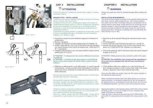
CAP. 4<br />
INSTALLAZIONE<br />
ATTENZIONE<br />
Prima di procedere all’ installazione del sollevatore, togliere l’ imballo e<br />
controllare la merce.<br />
CHAPTER 4<br />
WARNING<br />
INSTALLATION<br />
Unpack the goods and check for possible damage before installing the<br />
car lift.<br />
Fig.13 - Abb.13<br />
REQUISITI PER L’ INSTALLAZIONE<br />
Il sollevatore deve essere installato rispettando le distanze di sicurezza<br />
da muri, colonne, altre macchine etc.<br />
La distanza minima dai muri, considerando lo spazio per lavorare comodamente<br />
deve essere almeno di 1000 mm. Bisogna poi considerare<br />
gli spazi per la postazione di comando, per le vie di fuga in caso di<br />
emergenza. Il locale deve essere preventivamente predisposto per l’<br />
alimentazione elettrica.<br />
Il sollevatore può essere piazzato su qualsiasi tipo di pavimento, purchè<br />
lo stesso sia perfettamente piano, orizzontale, nonchè di resistenza<br />
adeguata ( min. 250 Kg. x cm2.).<br />
INSTALLATION REQUIREMENTS<br />
The car lift must be installed according to the specified safety distances<br />
from walls, columns, other equipments, etc. The minimum distance<br />
from walls must be 1000 mm at least, taking into consideration the necessary<br />
space to work easily. Further space for the control site and for<br />
possible runways in case of emergency is also necessary. The room<br />
must be previously arranged for the power supply.The car lift can be<br />
placed on any floor, as long as it is perfectly level and sufficiently resistant<br />
(250 Kg X sq.cm. Min).<br />
C<br />
Posizionare il ponte nel punto desiderato seguendo le indicazioni riportate<br />
sopra .<br />
Montare i salvapiedi<br />
Collegare i tubi idraulici A e B sulla centralina posta sul carrello(fig. 13)<br />
Svitare il tappo dell’olio ( pos.C fig.13) ed inserire olio nella centralina<br />
con imbuto introdurre circa 4 Kg di olio idraulico tipo “ ESSO NUTO H<br />
32 “ o equivalente .<br />
Collegare elettricamente il cavo all’impianto elettrico (vedere schema<br />
elettrico pag.14-15-16-17)<br />
Place the car lift as required following the instructions above indicated.<br />
Fit the foot guards.<br />
Connect hydraulic hoses Aand B to the power unit .( see fig.13)<br />
Unscrew the oil tank cap (pos.C Fig.13) and, using a funnel, pour<br />
about 4 lt of “ESSO-NUTO H32” hydraulic oil or equivalent.<br />
Connect the electrical cable to the electric plant (see electric diagram<br />
at page 14-15-16-17).<br />
ATTENZIONE ! Il collegamento deve essere effettuato da personale<br />
qualificato<br />
ATTENZIONE ! L’impianto di rete deve essere in conformità alle<br />
Norme e deve essere dotato dei fusibili relativi ( vedere schema<br />
elettrico )<br />
ATTENTION ! Skilled personnel only is allowed to perform this operation.<br />
ATTENTION !The installation must comply with the regulations in<br />
force and must be equipped with relevant fuses (see electrical<br />
intsllation).<br />
Fig.14 - Abb.14<br />
D<br />
Effettuare un sollevamento a vuoto della pedana ; in caso di mancato<br />
funzionamento , invertire una fase al fine di permettere la corretta rotazione<br />
del motore ,verificando se il livello dell'olio contenuto nel serbatoio<br />
diminuisce.<br />
Nella prova di funzionamento a vuoto verificare anche il corretto funzionamento<br />
delle sicurezze meccaniche .<br />
Se premendo il pulsante di discesa, l’azionamento delle sicure non è<br />
immediato, spurgare l’aria dai cilindretti delle sicure mediante lo svitamento<br />
della vite (fig.15 pos.D), quindi azionare la salita/discesa. Lasciare<br />
uscire aria e richiudere la vite.<br />
Lift the platform without any weight on it; in case the lift does not<br />
work, change one phase in order to let the motor rotate in the proper<br />
direction, observing, if the oil level inside the tank drops.<br />
During this test withou any weight, check also the correct operation of<br />
the mechanical safety devices.<br />
When pushing the lowering button if the safety devices are not immediately<br />
activated, it is necessary to bleed the air from the cylinders of<br />
the safety devices, by unscrewing the screw (fig.15 pos. D), then push<br />
the lifting/lowering button. Let the air come out and screw the screw.<br />
Fig.15 - Abb.15<br />
Tenendo la pedana in posizione di sollevamento massimo forare il pavimento<br />
con punta elicoidale diametro 15 mm. per una profondità di 70<br />
mm. usando come dima i fori posti sulla base .<br />
Pulire i fori , inserire i tasselli ( tipo HILTI HB M10/25/L - Fischer GM 10<br />
o equivalenti ) e quindi serrare con una coppia di serraggio di 20 Nm.<br />
Keeping the platform in the highest position, drill the floor with an helical<br />
bit having a diam. of 15 mm for a depth of 70 mm, using the holes<br />
made on the base as a template.<br />
Clean the holes, insert the anchor bolts (type HILTI HB M10/25/L - Fischer<br />
GM 10 or equivalent) and then tighten with a torque wrench of 20<br />
Nm.<br />
22