
You also want an ePaper? Increase the reach of your titles
YUMPU automatically turns print PDFs into web optimized ePapers that Google loves.
3 - INSTRUCTIONS D'EMPLOI 3 - INSTRUCTIONS FOR USE<br />
3.1. MISE EN MARCHE 3.1. STARTING UP<br />
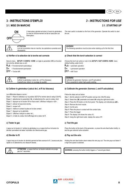
L’interrupteur général est situé à l’avant du générateur.<br />
La mise en fonctionnement se fait en basculant cet<br />
interrupteur.<br />
The main switch is situated on the front of the generator. Operate this switch to start<br />
the set.<br />
ATTENTION<br />
Lors de la première mise en marche, les opérations suivantes sont<br />
nécessaires :<br />
WARNING<br />
The following operations must be done when starting up for the first time:<br />
a) Vérifier si la sélection de la torche est correcte a) Check that the torch selection is correct<br />
Dans le menu SETUP CONFIG GRE on règle le paramètre GRE en fonction<br />
de la torche utilisée (eau ou air)<br />
Aut = Fonctionnement automatique<br />
On = Fonctionnement permanent<br />
OFF = Torche AIR<br />
Choose the torch (air active or not) in the SETUP SET CONFIGGRE menu<br />
(default setting, water torch)<br />
Aut = automatic operation<br />
On = permanent operation<br />
OFF = AIR Torch<br />
ATTENTION<br />
Calibrer le générateur (calcul de L et R du faisceau).<br />
Impératif pour obtenir un soudage de qualité)<br />
WARNING<br />
Calibrate the generator (harness L and R calculation).<br />
This is essential to obtain high-quality welding.<br />
b) Calibrer le générateur (calcul de L et R du faisceau) b) Calibrate the generator (harness L and R calculation).<br />
Les différentes étapes a suivre :<br />
Etape 1 : Placer le sélecteur sur la position SETUP et rentrer dans le setup COnFIG.<br />
Etape 2 : sélectionner le paramètre CaL et sélectionner On avec le codeur droit.<br />
Etape 3 : Appuyer sur le bouton OK en face avant, l’afficheur indique triGEr.<br />
Etape 4 : enlever la buse de la torche.<br />
Etape 5 : couper le fil.<br />
Etape 6 : mettre en contact la pièce et le tube contact.<br />
Etape 7 : Appuyer sur la gâchette.<br />
Etape 8 : l’afficheur indique la valeur de L.<br />
Etape 9 : à l’aide du codeur droit affichage de la valeur de R.<br />
Follow the steps set out below:<br />
Step 1: Set the selector to SETUP position and go into COnFIG setup<br />
Step 2: Select the CaL parameter and select On using the right-hand coder.<br />
Step 3: Press the OK button on the front panel. The display unit indicates triGEr.<br />
Step 4: Remove the torch nozzle.<br />
Step 5: Cut the wire.<br />
Step 6: Place the piece in contact with the contact tube.<br />
Step 7: Press the trigger<br />
Step 8: The display unit shows the value of L.<br />
Step 9: Using the right-hand coder, display the value of R.<br />
c) Tester le gaz c) Test the gas<br />
L’appui sur le bouton à l ‘arrière du générateur ou un appui bref sur le bouton du<br />
dévidoir permettent de tester l’activation de l’électrovanne gaz.<br />
Press the button at the back of the generator, or press the wire feed button briefly, to<br />
test the gas solenoid valve actuation.<br />
d) Dévider le fil d) Pay out the wire<br />
L’appui long sur le bouton du dévidoir permet de faire avancer le fil. L’avance est plus<br />
rapide si on sélectionne une vitesse fil élevée.<br />
Holding the wire feed button down makes the wire pay out. The wire pays out faster if<br />
a high wire speed is selected.<br />
ATTENTION : un appui bref sur ce bouton exécute une purge<br />
gaz de 7 secondes.<br />
WARNING: pressing the button briefly triggers a 7 second gas bleed.<br />
<strong>CITOPULS</strong> 8