20000 / 18000 Home Generator - NoOutage.com, LLC
20000 / 18000 Home Generator - NoOutage.com, LLC
20000 / 18000 Home Generator - NoOutage.com, LLC

Create successful ePaper yourself
Turn your PDF publications into a flip-book with our unique Google optimized e-Paper software.
• Install the flexible, gaseous hose (supplied) between<br />
the home generator Fuel Inlet port and rigid piping to<br />
prevent thermal expansion or contraction from causing<br />
excessive stress on the piping material.<br />
NOTE: Where local conditions include earthquake, tornado,<br />
unstable ground, or flood hazards, special consideration<br />
shall be given to increase strength and flexibility of piping<br />
supports and connections.<br />
caution<br />
The supplied flexible gaseous pipe is not to be installed<br />
underground or in contact with the ground.<br />
• The entire flexible gaseous pipe must be visible for<br />
periodic inspection and must not be concealed within,<br />
contact, or run through any wall, floor, or partition.<br />
• Piping must be of the correct size to maintain the<br />
required supply pressures and volume flow under<br />
varying generator load conditions with all gas<br />
appliances connected to the fuel system turned on and<br />
operating.<br />
• Use an approved pipe sealant or joint <strong>com</strong>pound on all<br />
threaded fittings to reduce the possibility of leakage.<br />
• Installed piping must be properly purged and leak<br />
tested, in accordance with applicable codes and<br />
standards.<br />
• Natural gas fuel supply pressure at the generator’s fuel<br />
inlet port should be between 5 to 7 inches of water (in.<br />
W.C.) at full load.<br />
• LP gas fuel supply pressure should be 11 to 14 inches<br />
of water (in. W.C.) at full load with all gas appliances<br />
turned on and operating.<br />
The home generator unit has been factory set to run on<br />
natural gas or LP gas. The unit cannot be converted from<br />
natural gas to LP gas or vice versa.<br />
It is re<strong>com</strong>mended that the fuel connection incorporate the<br />
following <strong>com</strong>ponents:<br />
• A manual fuel shut-off valve located in the interior of<br />
the building.<br />
• A manual fuel shut-off valve located outside the<br />
building, just before the generator unit.<br />
• Where the formation of hydrates or ice is known to<br />
occur, piping should be protected against freezing. The<br />
termination of hard piping should include a sediment<br />
trap where condensate is not likely to freeze.<br />
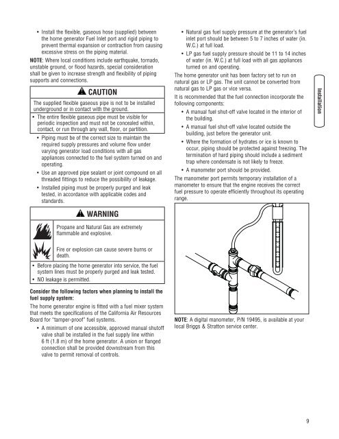
• A manometer port should be provided.<br />
The manometer port permits temporary installation of a<br />
manometer to ensure that the engine receives the correct<br />
fuel pressure to operate efficiently throughout its operating<br />
range.<br />
warning<br />
Propane and Natural Gas are extremely<br />
flammable and explosive.<br />
Fire or explosion can cause severe burns or<br />
death.<br />
• Before placing the home generator into service, the fuel<br />
system lines must be properly purged and leak tested.<br />
• No leakage is permitted.<br />
Consider the following factors when planning to install the<br />
fuel supply system:<br />
The home generator engine is fitted with a fuel mixer system<br />
that meets the specifications of the California Air Resources<br />
Board for “tamper-proof” fuel systems.<br />
• A minimum of one accessible, approved manual shutoff<br />
valve shall be installed in the fuel supply line within<br />
6 ft (1.8 m) of the home generator. A union or flanged<br />
connection shall be provided downstream from this<br />
valve to permit removal of controls.<br />
NOTE: A digital manometer, P/N 19495, is available at your<br />
local Briggs & Stratton service center.