20000 / 18000 Home Generator - NoOutage.com, LLC
20000 / 18000 Home Generator - NoOutage.com, LLC
20000 / 18000 Home Generator - NoOutage.com, LLC

Create successful ePaper yourself
Turn your PDF publications into a flip-book with our unique Google optimized e-Paper software.
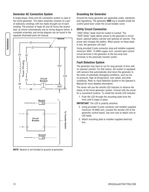
<strong>Generator</strong> AC Connection System<br />
A single-phase, three-wire AC connection system is used in<br />
the home generator. The stator assembly consists of a pair<br />
of stationary windings with two leads brought out of each<br />
winding. The junction of leads 22 and 33 forms the neutral<br />
lead, as shown schematically and as wiring diagram below. A<br />
<strong>com</strong>plete schematic and wiring diagram can be found in the<br />
separate illustrated parts list manual.<br />
Grounding the <strong>Generator</strong><br />
Ground the home generator per applicable codes, standards,<br />
and regulations. The generator GND lug is located inside the<br />
control panel door under the circuit breaker cover.<br />
Utility Circuit Connection<br />
“240V Utility” leads must be routed in conduit. The<br />
“240V Utility” leads deliver power to the generator’s circuit<br />
board, optional battery warmer and optional oil warmer. This<br />
power also charges the battery. When power on these leads<br />
is lost, the generator will start.<br />
Using provided 2 pole connector plug and installer-supplied<br />
minimum 300V, 14 AWG copper wire, connect each control<br />
circuit terminal in the generator to the two-amp fuse<br />
terminals in the automatic transfer switch.<br />
Fault Detection System<br />
The generator may have to run for long periods of time with<br />
no operator present. For that reason, the system is equipped<br />
with sensors that automatically shut down the generator in<br />
the event of potentially damaging conditions, such as low<br />
oil pressure, high oil temperature, over speed, and other<br />
conditions. Refer to Fault Detection System in the Operator’s<br />
Manual for more detailed information.<br />
The owner will use the remote LED indicator to observe the<br />
status of the home generator system. Consult with the owner<br />
for a convenient location. To install the remote LED indicator:<br />
1. Push the LED through the mounting plate from the<br />
front until it snaps in place.<br />
IMPORTANT: The LED is polarity sensitive.<br />
2. Using provided 10 pole connector and installer-supplied<br />
minimum 18 AWG wire, connect the remote LED to the<br />
generator control board. Use wire nuts to attach wire to<br />
LED leads.<br />
3. Attach mounting plate to installer-supplied electrical<br />
box.<br />
NOTE: Neutral is not bonded to ground at generator.<br />
12<br />
BRIGGSandSTRATTON.COM