Broan Elite EPD61 Series Installation Manual (SV20571 rev 02 ...
Broan Elite EPD61 Series Installation Manual (SV20571 rev 02 ...
Broan Elite EPD61 Series Installation Manual (SV20571 rev 02 ...

You also want an ePaper? Increase the reach of your titles
YUMPU automatically turns print PDFs into web optimized ePapers that Google loves.
! WARNING! WARNINGTO REDUCE THE RISK OF FIRE, ELECTRICSHOCK OR INJURY TO PERSONS, OBSERVETHE FOLLOWING:TO REDUCE THE RISK OF INJURY TO PERSONSIN THE EVENT OF A RANGE TOP GREASEFIRE, OBSERVE THE FOLLOWING*:1. Use this unit only in the manner intended by themanufacturer. If you have questions, contact themanufacturer at the address or telephone numberlisted in the warranty.2. Before servicing or cleaning unit, switch power offat service panel and lock service disconnectingmeans to p<strong>rev</strong>ent power from being switched onaccidentally. When the service disconnectingmeans cannot be locked, securely fasten a prominentwarning device, such as a tag, to the service panel.3. <strong>Installation</strong> work and electrical wiring must be doneby qualified personnel in accordance with allapplicable codes and standards, includingfire-rated construction codes and standards.4. Sufficient air is needed for proper combustion andexhausting of gases through the flue (chimney) offuel burning equipment to p<strong>rev</strong>ent backdrafting.Follow the heating equipment manufacturer’sguidelines and safety standards such as thosepublished by the National Fire ProtectionAssociation (NFPA), and the American Society forHeating, Refrigeration and Air ConditioningEngineers (ASHRAE), and the local code authorities.5. When cutting or drilling into wall or ceiling, do notdamage electrical wiring and other hidden utilities.6. Ducted fans must always be vented to the outdoors.7. Do not use this unit with any additional solid-statespeed control device.8. To reduce the risk of fire, use only metal ductwork.9. This unit must be grounded and protected by aGFCI.10. Suitable for use in damp locations only when installedin a GFCI PROTECTED branch-circuit.11. This unit is not designed to be used with a charcoalgrill.12. When applicable local regulations comprise morerestrictive installation and/or certificationrequirements, the aforementioned requirementsp<strong>rev</strong>ail on those of this document and the installeragrees to conform to these at his own expenses.TO REDUCE THE RISK OF A RANGE TOPGREASE FIRE:a) Never leave surface units unattended at highsettings. Boilovers cause smoking and greasyspillovers that may ignite. Heat oils slowly on low ormedium settings.b) Always turn hood ON when cooking at high heat orwhen flambeing food (i.e.: Crêpes Suzette,Cherries Jubilee, Peppercorn Beef Flambé).c) Clean ventilating fans frequently. Grease shouldnot be allowed to accumulate on fans, filters orexhaust ducts.d) Use proper pan size. Always use cookwareappropriate for the size of the surface element.1. SMOTHER FLAMES with a close-fitting lid,cookie sheet or metal tray, then turn off the burner.BE CAREFUL TO PREVENT BURNS. IF THEFLAMES DO NOT GO OUT IMMEDIATELY,EVACUATE AND CALL THE FIRE DEPARTMENT.2. NEVER PICK UP A FLAMING PAN – You may beburned.3. DO NOT USE WATER, including wet dishclothsor towels – This could cause a violent steamexplosion.4. Use an extinguisher ONLY if:A. You own a Class ABC extinguisher and youknow how to operate it.B. The fire is small and contained in the areawhere it started.C. The fire department has been called.D. You can fight the fire with your back to an exit.*Based on “Kitchen Fire Safety Tips” published by NFPA.CAUTION1. For general ventilating use only. Do not use toexhaust hazardous or explosive materials andvapors.2. To avoid motor bearing damage and noisy and/orunbalanced impellers, keep drywall spray,construction dust, etc. off power unit.3. Your hood motor has a thermal overload which willautomatically shut off the motor if it becomesoverheated. The motor will restart when it will becooled down. If the motor continues to shut off andrestart, have the hood serviced.4. For best capture of cooking impurities, the bottomof the hood must be located at a minimum distanceof 36" above cooking surface.5. Two installers are recommended because of thelarge size and weight of this hood.6. To reduce the risk of fire and to properly exhaustair, be sure to duct air outside—Do not exhaust airinto spaces within walls or ceiling or into attics,crawl space or garage.7. This product is equipped with a thermostat whichmay start blower automatically. To reduce the riskof injury and to p<strong>rev</strong>ent power from being switchedon accidentally, switch power off at service paneland lock or tag service panel.8. Please read specification label on product forfurther information and requirements.- 2 -
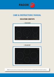
1. INSTALL DUCTWORK AND ELECTRICAL WIRINGCAUTIONThis range hood is intended for outdoor covered patio or lanai area. As with allelectric appliances, this unit must be protected from the effects of weather.! WARNINGThis range hood is not designed for use with a charcoal grill.ROOF CAPPlan where and how the ductwork will be installed.A straight, short duct run will allow the hood toperform most efficiently.Install proper-sized ductwork, elbows and roof or wallcap. Connect metal ductwork to cap and work backtowards the hood location. Use 2” metal foil duct tapeto seal the joints.Run 3-wire power supply cable to installation location.! WARNINGThe power cable must be a GFCI protectedbranch circuit.For best capture of cooking impurities, the bottomof the hood must be located at a minimumdistance of 36" above cooking surface.10" ROUND DUCTOPTIONAL DECORATIVEFLUE OR SOFFIT10" ROUND ELBOW18"16" TOTOP OF WOODMOUNTING STRIP36" MINIMUM ABOVECOOKING SURFACEWALL CAP10" ROUNDADAPTERHH0182A2. PREPARE INSTALLATION! WARNINGWhen performing installation, servicing or cleaning the unit, it is recommendedto wear safety glasses and gloves.NOTE: Before proceeding to the installation, check the contents of the box. If items are missing ordamaged, contact the manufacturer.Make sure that the following items are included:- Range hood- Wood strip (attached to back of hood)- <strong>Installation</strong> manual- Accessories including:• Baffle filters with handles: 3 for 36” width model and 4 for 48” width model• 10” round adapter (taped inside the hood)• Bag of parts: 3 waterproof wire connectors, 2 no. 8 x 5/8’’ screws, 6 no. 10 x 2’’ hex head screws,4 no. 10 x 2” flat head screws, 2 wall anchors, 2 washers 3/16’’ ID x 3/4’’ ODIncluded in parts bag, but not to be used (please discard): 2 wire clamps LP16-AP,2 no. 8 x 3/8’’ zinc-plated screws, 8 no. 8 x 3/8’’ stainless steel screws,4 stainless steel 10-32 locknuts, 4 washers 3/16’’ ID x 3/4’’ OD- 4 -
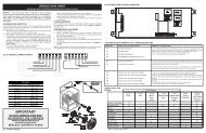
6. INSTALL ADAPTERRemove adapter from inside hood.Using both no. 8 x 3/8” zinc-plated screws from partsbag, assemble the adapter on the top of the hood.Seal all joints with metal foil duct tape to eliminate airleaks.MOUNTING SCREWS LOCATIONHJ00697. INSTALL WOOD MOUNTING STRIP (IF NOT USING WALL EXTENSION)CAUTIONDue to the weight of this hood, ensure that the wood strip is attached to all ofthe available wall studs and blocking; not into the wall alone.NOTE: If range hood is installed with optional wall extension, refer to the instructions sheet includedwith the wall extension for wood mounting strip location.1. Proper structural support is required to accommodate the weight of the hood. Construct the wallframing using minimum 2" x 4" lumber.2. Mark the center location of the hood.3. Measure and mark a level line on wall above cooktop location for the wood mounting strip (seeillustration on page 4). Install 2" x 4" blockings between wall studs where mounting strip will beinstalled. Refer to illustration at right.4. Remove wood mounting strip from back of hood.5. Position the wood mounting strip on the wall and secure to the wall studs and blockings using4 no. 10 x 2’’ flat head screws (included in parts bag).ExistingWall StudsWood MountingStripBack of Hood2" x 4"Blocking18"16"14¼" 15 1 ⁄8"HD0482A- 6 -
8. INSTALL HOODCAUTION• Although not recommended, if blowers need to be removed, reinstall themusing the 10-32 locknuts included in parts bag (maximum torque of 20 lb.).• Hold the hood until it is completely secured to the wood mounting strip.Remove the electrical compartmentcover. Insert the house wiring in thehood and tighten the wire clamp tosecure the wiring.ELECTRICAL COMPARTMENT COVERHD0469Rest the back cavity of the hood onthe wood mounting strip.Attach 10” round duct to adapter.Secure the hood to wood mountingstrip using 4 no. 10 x 2’’ hex headscrews (for 36’’ width hood) or 6 screws(for 48’’ width hood) at locationsshown at right. Drill two 3/16’’ diameterholes into the wall for wall anchorsthrough the existing holes in the lowerback of the hood at locations shown atright. Then, install both wall anchorswith both no. 8 x 5/8’’ screws and bothwashers provided.HD0470MOUNTING SCREWS LOCATIONWALL ANCHORS LOCATION9. INSTALL DECORATIVE FLUE (OPTIONAL)AEEPD <strong>Series</strong>Refer to the instructions included with the optional decorative flue.10. CONNECT WIRING! WARNINGRisk of electric shock. Electrical wiring must be done by qualified personnel inaccordance with all applicable codes and standards. Before connecting wires,switch power off at service panel and lock service disconnecting means top<strong>rev</strong>ent power to be switched on accidentally.WATERPROOF WIRE CONNECTORS INSTRUCTIONS:1. Strip wires 3/8’’.2. Align frayed strands or conductors.3. Do not pre-twist. Place stripped wires together with ends even, but lead smaller stranded wiresslightly ahead of larger solid or stranded wire.4. Twist connector onto wires pushing firmly until hand-tight. DO NOT over torque.5. When inserting wires into connectors, some sealant may leak out. Wipe off excess sealant inand around conductors. DO NOT REUSE.- 7 -
10. CONNECT WIRING (CONT’D)Connect cable into electrical compartmentusing provided waterproof wire connectors.Connect BLACK to BLACK, WHITE to WHITEand GREEN or bare wire under ground screw.Reinstall electrical compartment cover.HE013811. REINSTALL GREASE DRIP RAIL AND BAFFLE FILTERSReinstall grease drip rail. The illustration at rightshows how to reinsert the grease drip rail into therange hood.HD0472CAUTIONRemove protective plastic film covering filters before installing them.It is recommended to install side filters first and finish with center one(s).1. Insert one end of the filter into the upper channel of the hood.2. Raise the other end toward the inside of hood and insert in the grease drip rail of the hood.12HD0473- 8 -
12. LIGHT BULBS REPLACEMENTThis hood requires 120 V, 50 W, MR16 with GU10 base, shielded halogen lamps (not included).(2 for 36” width hood and 3 for 48” width hood.)! WARNINGDo not touch lamps during or soon after operation. Burns may occur. In order top<strong>rev</strong>ent the risk of personal injury, only install shielded halogen lamps. Also,never install a cool beam, a dichroïc lamp, a lamp not suitable for use inrecessed luminaires or identified for use in enclosed fixtures.1. To remove lamps, gently push upwards andturn counterclockwise to disengage bulb leadsfrom their grooves.2. Install the new lamps by placing the bulb leadsinto their grooves in the socket.3. Gently push upwards and turn clockwise untilsecure.NOTE: If need be, use a rubber dishwashingglove to add grip when removing the bulb.HO00891 2 313. CAREBaffle FiltersThe baffle filters should be cleaned frequently. Use a warm detergent solution. Wash more oftenif your cooking style generates greater grease like frying foods or wok cooking.Remove baffle filters by pushing them towards the front of the hood and rotating filters downward.Baffle filters are dishwasher safe. Allow filters to dry completely before reinstalling them in the hood.Clean all-metal filters in the dishwasher using a non-phosphate detergent. Discoloration of thefilter may occur if using phosphate detergent or as a result of local water conditions—but this willnot affect filter performance. This discoloration is not covered by the warranty.Grease Drip RailThe grease drip rail should be cleaned frequently. Lift it out from the hood and use a warm detergentsolution. As for the baffle filters, wash more often if your cooking style generates greater greaselike frying foods or wok cooking. Allow grease drip rail to dry completely before reinstalling it in thehood.Blowers Cleaning (Internal)Remove the filters in order to access the blowers. Vacuum blowers to clean. Do not immerse inwater.Hood CleaningStainless steel cleaning:Do:• Regularly wash with clean cloth or ragsoaked with warm water and mild soap orliquid dish detergent.• Always clean in the direction of original polishlines.• Always rinse well with clear water (2 or 3times) after cleaning. Wipe dry completely.• You may also use a specialized householdstainless steel cleaner.- 9 -Don’t:• Use any steel or stainless steel wool or anyother scrapers to remove stubborn dirt.• Use any harsh or abrasive cleansers.• Allow dirt to accumulate.• Let plaster dust or any other constructionresidues reach the hood. During construction/renovation, cover the hood to make sure nodust sticks to stainless steel surface.Avoid when choosing a detergent:• Any cleaners that contain bleach will attack stainless steel.• Any products containing: chloride, fluoride, iodide, bromide will deteriorate surfaces rapidly.• Any combustible products used for cleaning such as acetone, alcohol, ether, benzol, etc.,are highly explosive and should never be used close to a range.
14. OPERATION1 2HC00591) BLOWER SPEED CONTROL KNOB2) HALOGEN LIGHT SWITCHBLOWERA rotary 4-position knob (1) controls the blower (OFF - Low - Medium - High).Turn the speed control knob clockwise to increase blower speed – counterclockwise to decreasespeed.COOKTOP LIGHTING (HALOGEN)Use the on/off rocker switch (2) to turn the halogen lights ON or OFF.HEAT SENTRYThis hood is equipped with a Heat Sentry thermostat. This thermostat is a device that will turnon the blower if it senses excessive heat above the cooking surface.1) If blower is OFF - it turns blower ON to medium speed.2) If blower is already ON speed will remain the same.! WARNINGThe HEAT SENTRY can start the blower during a range top fire or other excessiveheat situations even if the hood is turned off. In this case, it is impossible to turnthe blower OFF using control panel switch. To stop the blower, set the mainpower switch located behind the baffle filters in OFF position, if it is possible todo so safely.When the temperature level drops to normal, the blower will return to its original setting.MAIN POWERSWITCHHD0467- 10 -
15. WIRING DIAGRAMHEAT SENTRYTHERMOSTATMAIN SWITCHORMAIN SWITCHBLKBLKAB1 OFF234REDREDBLUORABLKBLUORABLKBLUORABLKWHTBLUWHTORABLKREDMGRYBRN120 VACLINENEUTRALGROUNDBLKBLKBLKLAMPSWITCHYELCOLOR CODEBLK BLACKBLU BLUEBRN BROWNGRY GREYORA ORANGERED REDWHT WHITEYEL YELLOWWHTYELYELWHTWHTWHTWHTWHTYELWHTBLUORABLKWHTBLUWHTORABLKREDMGRYBRNHE0137ALAMP LAMP LAMP16. WARRANTYONE YEAR LIMITED WARRANTY FOR BROAN ELITE PRODUCTS<strong>Broan</strong>-NuTone LLC (<strong>Broan</strong>-NuTone) warrants to the original consumer purchaser of <strong>Broan</strong> <strong>Elite</strong> products thatsuch products will be free from defects in materials or workmanship for a period of one year from the date oforiginal purchase. THERE ARE NO OTHER WARRANTIES, EXPRESS OR IMPLIED, INCLUDING, BUT NOTLIMITED TO, IMPLIED WARRANTIES OR MERCHANTABILITY OR FITNESS FOR A PARTICULAR PURPOSE.During this one-year period, <strong>Broan</strong>-NuTone will, at its option, repair or replace, without charge, any product orpart which is found to be defective under normal use and service.THIS WARRANTY DOES NOT EXTEND TO FLUORESCENT LAMP STARTERS, TUBES, HALOGEN ANDINCANDESCENT BULBS, FUSE, FILTERS, DUCTS, ROOF CAPS, WALL CAPS AND OTHER ACCESSORIESFOR DUCTING. This warranty does not cover (a) normal maintenance and service or (b) any products or partswhich have been subject to misuse, negligence, accident, improper maintenance or repair (other than by<strong>Broan</strong>-NuTone), faulty installation or installation contrary to recommended installation instructions.The duration of any implied warranty is limited to the one-year period as specified for the express warranty.Some states or provinces do not allow limitation on how long an implied warranty lasts, so the above limitationmay not apply to you.BROAN-NUTONE’S OBLIGATION TO REPAIR OR REPLACE, AT BROAN-NUTONE’S OPTION, SHALL BETHE PURCHASER’S SOLE AND EXCLUSIVE REMEDY UNDER THIS WARRANTY. BROAN-NUTONESHALL NOT BE LIABLE FOR INCIDENTAL, CONSEQUENTIAL OR SPECIAL DAMAGES ARISING OUT OFOR IN CONNECTION WITH PRODUCT USE OR PERFORMANCE. Some states or provinces do not allow theexclusion or limitation of incidental or consequential damages, so the above limitation or exclusion may notapply to you.This warranty gives you specific legal rights, and you may also have other rights, which vary from state to stateor province to another. This warranty supersedes all prior warranties.To qualify for warranty service, you must (a) notify <strong>Broan</strong>-NuTone at one of the addresses or telephone number statedbelow, (b) give the model number and part identification and (c) describe the nature of any defect in the productor part. At the time of requesting warranty service, you must present evidence of the original purchase date.USA - <strong>Broan</strong>-NuTone LLC; 926 W. State Street, Hartford, Wisconsin 53<strong>02</strong>7 www.broan.com 800-558-1711Canada - <strong>Broan</strong>-NuTone Canada; 1140 Tristar Drive, Mississauga, ON L5T 1H9 www.broan.ca 877-896-1119- 11 -
17. SERVICE PARTS1REPLACEMENT PARTS AND REPAIRS211910 78In order to ensure your ventilation unitremains in good working condition, youmust use <strong>Broan</strong>-NuTone genuinereplacement parts only. <strong>Broan</strong>-NuTonegenuine replacement parts are speciallydesigned for each unit and aremanufactured to comply with all theapplicable certification standards andmaintain a high standard of safety. Anythird party replacement part used maycause serious damage and drasticallyreduce the performance level of yourunit, which will result in prematurefailing. <strong>Broan</strong>-NuTone recommends tocontact a certified service depot for allreplacement parts and repairs.435HL01876KEYNO.PART NO.DESCRIPTION- 12 -QTY. (RANGE HOOD WIDTH)36” 48”1 SV08541 10” ROUND ADAPTER 1 12 SV16569 LIGHT SOCKET AND TRIM ASSEMBLY 2 33 SV08582 BLOWER 2 24 SV08337 FILTER SPRING 3 45 SV60675 BAFFLE FILTERS 11.84” X 15.125” (SPRING INCLUDED) 3 46SV60695 GREASE RAIL 36”1-SV60696 GREASE RAIL 48”-17 SV<strong>02</strong>563 LIGHT ROCKER SWITCH 1 18 SV08095 FAN KNOB 1 19 SV03435 HEAT SENTRY THERMOSTAT 1 110 SV08968 SPEED CONTROL 1 111 SV08548 MAIN POWER SWITCH 1 1* SV06750 BROAN ELITE LOGO 1 1* <strong>SV20571</strong> INSTALLATION GUIDE 1 1* SV04216*NOT SHOWN.PARTS BAG: 3 WATERPROOF WIRE CONNECTORS,2 NO. 8 X 5/8’’ SCREWS, 6 NO. 10 X 2’’ HEX HEAD SCREWS,4 NO. 10 X 2” FLAT HEAD SCREWS, 2 WALL ANCHORS,6 WASHERS 3/16’’ ID X 3/4’’ OD, 4 STAINLESS STEEL 10-32LOCKNUTS, 2 WIRE CLAMPS LP16-AP, 2 NO. 8 X 3/8’’ZINC-PLATED SCREWS, 8 NO. 8 X 3/8” STAINLESS STEEL SCREWS1 1
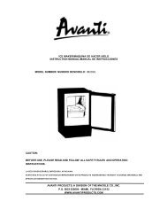
- SYSTÈME DE HOTTE DE CUISINIÈRE SÉRIE <strong>EPD61</strong> -MODÈLE 441(CAPUCHON MURAL 10 PO ROND)MODÈLE 437(CAPUCHON DE TOITÀ HAUT RENDEMENT)MODÈLE 418(COUDE AJUSTABLEDE 10 PO ROND)MODÈLE 410(CONDUIT 10 PO ROND,SECTIONS 2 PI)CHEMINÉE DÉCORATIVEOPTIONNELLESÉRIE AEEPDRALLONGE DE HOTTEOPTIONNELLESÉRIE AWEPDADAPTATEUR ROND DE 10 PO(INCLUS)HOTTESÉRIE <strong>EPD61</strong>HL0186VENTILATEUR DOUBLE(INCLUS)- 15 -
1. INSTALLER LES CONDUITS ET LE CÂBLAGE ÉLECTRIQUEATTENTIONCette hotte est conçue pour être utilisée sur un patio couvert ou une véranda.Comme tous les électroménagers, cet appareil doit être à l’abri des intempéries.! AVERTISSEMENTCette hotte n’est pas conçue pour être utilisée avec un barbecue au charbon de bois.Déterminer à quel endroit et comment les conduitsseront installés.Un conduit droit et court permettra à votre hotte defonctionner plus efficacement.Installer des conduits de dimensions adéquates, descoudes et un capuchon de toit ou de mur. Relier leconduit de métal au capuchon, puis acheminer le conduitjusqu’à l’emplacement de votre hotte. Sceller les jointsavec du ruban adhésif de métal de 2 po de largeur.Acheminer un câble d’alimentation électrique à3 conducteurs jusqu’à l’emplacement de la hotte.CONDUIT ROND DE 10 POCHEMINÉE DÉCORATIVEOPTIONNELLE OU SOFFITECOUDE ROND DE 10 PO18 PODISTANCE DE16 PO JUSQU’AUDESSUS DE LALISIÈRE DE BOISCAPUCHON DE TOITCAPUCHONMURALADAPTATEUR10 PO ROND! AVERTISSEMENTLe fil d’alimentation électrique doit être raccordéà un disjoncteur de fuite à la terre (DDFT).Pour une meilleure évacuation des odeurs decuisson, le bas de votre hotte doit être situé à unedistance minimale de 36 po au-dessus de lasurface de cuisson.HH0182FMINIMUM DE 36 POAU-DESSUS DE LASURFACE DE CUISSON2. PRÉPARER L’INSTALLATION! AVERTISSEMENTIl est recommandé de porter des lunettes et des gants de sécurité lors del’installation, de l’entretien et de la réparation de cet appareil.NOTE : Avant de commencer l'installation, vérifier le contenu de la boîte. Si des pièces sontmanquantes ou endommagées, contacter le manufacturier.S’assurer que les articles suivants soient inclus :- Hotte- Lisière de bois (fixée au dos de la hotte)- Guide d’installation- Les accessoires incluant :• Filtres à chicane avec poignées : 3 pour le modèle de 36 po de largeur et 4 pour le modèle de48 po de largeur• Adaptateur de 10 po rond (fixé avec du ruban adhésif à l’intérieur de la hotte)• Sac de pièces : 3 capuchons de connexion étanches, 2 vis n° 8 x 5/8 po,6 vis à tête hexagonale n° 10 x 2 po, 4 vis à tête fraisée n° 10 x 2 po,2 douilles à expansion, 2 rondelles de 3/16 po DI x 3/4 po DEInclus dans le sac de pièces, mais à ne pas utiliser (svp jeter) :2 serre-fils LP16-AP, 2 vis n° 8 x 3/8 po plaquées zinc,8 vis en acier inoxydable n° 8 x 3/8 po, 4 contre-écrous 10-32 en acier inoxydable,4 rondelles de 3/16 po DI x 3/4 po DE- 16 -
2. PRÉPARER L’INSTALLATION (SUITE)Pièces vendues séparément :- Ampoules halogènes avec écran (120 V, 50 W max., MR16 à culot GU10) (2 pour le modèle de36 po de largeur et 3 pour le modèle de 48 po de largeur)- Cheminée décorative de série AEEPD, à être installée au-dessus de la hotte (optionnelle)- Rallonge de hotte de série AWEPD, 36 po ou 48 po de largeur (optionnelle)- Transitions, conduits, coudes, volets, capuchons de mur ou de toitConsulter la page 15 pour la liste complète des accessoires de ventilation et les numéros de modèle.NOTE : Lors de l’installation, protéger la surface de cuisson et le comptoir de cuisine.3. INSTALLER LA RALLONGE DE HOTTE (OPTIONNELLE)Série AWEPDLa rallonge de hotte doit être installée avant la hotte (voir les directives fournies avec la rallonge).4. RETIRER L’OUVERTURE PRÉAMORCÉEDéfoncer l’ouverture préamorcée pour le fild’alimentation située à l’arrière de la hotte. Installer leserre-fils (inclus dans le sac de pièces).HR00735. RETIRER LES FILTRES ET LA GOUTTIÈREA. Enlever le ruban adhésif des filtres.Retirer les filtres de la hotte et les mettre de côté.NOTE : Il est recommandé de commencer par celui (ceux) du centre.B. Enlever le ruban adhésif de la gouttière (1).Retirer la gouttière et la mettre de côté.1HD0471A- 17 -B
6. INSTALLER L’ADAPTATEURRetirer l’adaptateur de l’intérieur de la hotte.À l’aide des 2 vis n° 8 x 3/8 po plaquées zinc (inclusesdans le sac de pièces), assembler l’adaptateur sur ledessus de la hotte. Sceller les joints avec du rubanadhésif de métal pour éliminer les fuites d’air.EMPLACEMENT DES VIS D’ASSEMBLAGEHJ00697. INSTALLER LA LISIÈRE DE BOIS (SI LA RALLONGE DE HOTTE N’EST PAS UTILISÉE)ATTENTIONEn raison du poids élevé de cette hotte, s’assurer que la lisière de bois soit bienrattachée à tous les montants et entretoises disponibles; ne pas visser la lisièrede bois seulement au mur.NOTE : Si la hotte est installée avec la rallonge optionnelle, se référer aux instructions inclusesavec la rallonge pour l’emplacement de la lisière de bois.1. Une structure de soutien appropriée est nécessaire afin de supporter adéquatement le poidsde la hotte. Construire la charpente du mur à l’aide de montants en 2 po x 4 po minimum.2. Marquer l’emplacement du centre de la hotte.3. Mesurer et tracer une ligne droite au-dessus de la surface de cuisson pour l’emplacement dela lisière de bois (voir l’illustration en page 16). Installer des entretoises en 2 po x 4 po entre lesmontants où la lisière de bois sera installée. Voir l’illustration ci-contre.4. Retirer la lisière de bois de l’arrière de la hotte.5. Placer la lisière de bois au mur et la fixer aux montants et aux entretoises à l’aide de 4 visn° 10 x 2’’ po à tête fraisée (incluses dans le sac de pièces).MontantsactuelsLisièrede boisDos de la hotteEntretoiseen 2 po x 4 po14¼ po18 po16 po15 1 ⁄8 poHD0482F- 18 -
8. INSTALLER LA HOTTEATTENTION• Bien que non recommandé, si les ventilateurs doivent être retirés, les réinstallerà l’aide des contre-écrous 10-32 inclus dans le sac de pièces (force de torsionmaximale de 20 lb).• Retenir la hotte jusqu’à ce qu’elle soit complètement vissée à la lisière de bois.Retirer le couvercle de la boîte dejonction. Insérer le câble d’alimentationélectrique dans la hotte par le serre-filset serrer le serre-fils pour le mainteniren place.COUVERCLE DE LA BOÎTEDE JONCTIONHD0469En appuyant la hotte au mur, insérerla lisière de bois dans la cavité arrièrede la hotte.Attacher le conduit rond de 10 poà l’adaptateur.Fixer la hotte à la lisière de bois, auxendroits indiqués, à l’aide de 4 visn° 10 x 2 po à tête hexagonale (pourle modèle de 36 po de largeur) ou de6 vis (pour le modèle de 48 po delargeur) fournies. En se servant destrous existants dans la hotte, percer lemur, aux endroits indiqués, de 2 trousde 3/16 po et y insérer les douilles àexpansion. Puis, fixer la hotte au muravec les 2 vis n° 8 x 5/8 po et les2 rondelles fournies.HD047010. BRANCHEMENT ÉLECTRIQUEEMPLACEMENT DES VIS DE RETENUEEMPLACEMENT DES DOUILLES9. INSTALLER LA CHEMINÉE DÉCORATIVE (OPTIONNELLE)Série AEEPDVoir les directives fournies avec la cheminée décorative optionnelle.! AVERTISSEMENTRisque d’électrocution. Le raccordement électrique doit être effectué par dupersonnel qualifié conformément aux codes et aux standards. Avant d’effectuerle branchement, coupez l’alimentation électrique au panneau de distribution etverrouillez-le pour éviter une mise en marche accidentelle.DIRECTIVES POUR L’UTILISATION DES CAPUCHONS DE CONNEXION ÉTANCHES :1. Dégainer les fils d’une longueur de 3/8 po.2. Égaliser les brins ou les conducteurs.3. Ne pas les tordre. Rapprocher les fils et mettre leurs bouts égaux, sauf pour les fils à brinsplus petits, lesquels doivent dépasser légèrement des fils plus gros.4. Insérer les fils dans le capuchon de connexion en poussant légèrement et tordre. NE PAStrop tordre.5. Un peu de scellant pourrait s’échapper lors de l’insertion des fils dans le capuchon deconnexion. Essuyer l’excès de scellant autour des conducteurs. NE PAS RÉUTILISER.- 19 -
10. BRANCHEMENT ÉLECTRIQUE (SUITE)Connecter les fils aux fils du câble d’alimentationdans la boîte de jonction à l’aide descapuchons de connexion étanches fournis.Connecter le fil NOIR au NOIR, le fil BLANCau BLANC et le fil VERT ou DÉNUDÉ à la visde mise à la terre.Remettre le couvercle de la boîte de jonctionen place.HE013811. RÉINSTALLER LA GOUTTIÈRE ET LES FILTRES À CHICANERéinstaller la gouttière. L’image ci-contre illustre lafaçon de réinsérer la gouttière dans la hotte.HD0472ATTENTIONAvant d’installer les filtres à chicane, retirer la pellicule de plastique protectricede ceux-ci.Il est recommandé d’installer d’abord les filtres situés aux extrémités et de terminer par le(s) filtre(s)du centre.1. Introduire une extrémité du filtre dans le rail avant de la hotte.2. Lever l’autre bout du filtre à l’intérieur de la hotte et l’introduire dans la gouttière.12HD0473- 20 -
12. REMPLACEMENT DES AMPOULESL’éclairage de cette hotte est produit par des ampoules halogènes avec écran de 120 V, 50 W, MR16à culot GU10 (non incluses). (2 pour le modèle de 36 po et 3 pour le modèle de 48 po de largeur.)! AVERTISSEMENTNe pas toucher aux lampes durant ou peu après leur utilisation. Peuvent causer des brûlures.Afin de réduire le risque de blessures corporelles, n’installer que des ampoules halogènesavec écran. Aussi, ne jamais installer une ampoule à faisceau froid, dichroïque, non conçuepour des luminaires encastrés ou conçue uniquement pour des luminaires fermés.1. Pour retirer les ampoules, pousser doucementvers le haut et tourner dans le sens contraire1 2 3des aiguilles d’une montre pour désengagerles conducteurs hors de leur rainure.2. Installer les nouvelles ampoules en glissantleurs conducteurs dans les rainures, àl’intérieur des douilles.3. Pousser doucement vers le haut et tourner HO0089dans le sens des aiguilles d’une montrejusqu’à ce que les ampoules soient bien en place.NOTE : Si nécessaire, utiliser un gant à vaisselle pour obtenir une meilleure prise de l’ampoulelors de son retrait.13. ENTRETIENFiltres à chicaneLes filtres à chicane doivent être nettoyés fréquemment. Utiliser une solution d’eau chaude et dedétergent. Les filtres à chicane doivent être lavés plus souvent si vos habitudes de cuissongénèrent plus de graisse, par exemple de la friture ou des aliments sautés au wok. Retirer lesfiltres en les poussant vers l’avant de la hotte et en les retournant vers le bas.Les filtres à chicane sont lavables au lave-vaisselle. Nettoyer les filtres fabriqués entièrement demétal au lave-vaisselle à l’aide d’un détergent sans phosphate. L’utilisation d’un détergent avecphosphates ainsi que les conditions locales de l’eau peuvent entraîner une décoloration desfiltres, sans toutefois affecter leur performance. Cette décoloration n’est pas couverte par lagarantie. Laisser les filtres sécher complètement avant de les réinstaller dans la hotte.GouttièreLa gouttière doit être nettoyée fréquemment. Pour ce faire, la désengager de la hotte et utiliser unesolution d’eau chaude et de détergent. Tout comme les filtres à chicane, la laver plus souvent si voshabitudes de cuisson génèrent plus de graisse, par exemple de la friture ou des aliments sautés auwok. Essuyer complètement la gouttière avant de la réinstaller dans la hotte.Nettoyage des ventilateursRetirer les filtres pour accéder aux ventilateurs. Passer l’aspirateur pour les nettoyer, ne pasimmerger dans l’eau.Nettoyage de la hotteAcier inoxydable :À faire :• Laver régulièrement les surfaces à l’aide d’unchiffon ou linge propre imbibé d’eau tiède et desavon doux ou détergent liquide à vaisselle.• Toujours nettoyer dans le sens du polissage.• Toujours bien rincer avec de l’eau claire (2 à3 fois) et essuyer complètement.• Un nettoyant domestique conçu spécialementpour l’acier inoxydable peut aussi être utilisé.À ne pas faire :• Utiliser une laine d’acier ou d’acier inoxydableou tout autre grattoir pour enlever la saleté tenace.• Utiliser une poudre nettoyante abrasiveou rugueuse.• Laisser la saleté s’accumuler.• Laisser la poussière de plâtre ou tout autrerésidu de construction atteindre la hotte.Couvrir la hotte pour la durée des travauxafin de s’assurer qu’aucune poussièren’atteigne la hotte.À éviter lors du choix du détergent :• Tous produits nettoyants contenant des agents de blanchiment; ils attaqueront l’acier inoxydable.• Tous les produits contenant du chlorure, du fluorure, de l’iode ou du bromure; ils détériorerontrapidement les surfaces.• Tous produits combustibles utilisés pour le nettoyage : acétone, alcool, éther, benzol, etc., ilssont hautement explosifs et ne devraient jamais être utilisés près d’une cuisinière.- 21 -
14. FONCTIONNEMENT1 2HC00591) BOUTON DE LA COMMANDE DE VITESSE DU VENTILATEUR2) INTERRUPTEUR D’ÉCLAIRAGE HALOGÈNEVENTILATEURUn bouton rotatif à 4 positions (1) contrôle le ventilateur (Arrêt - Basse vitesse - Moyenne vitesse- Haute vitesse).Tourner le bouton de la commande de vitesse dans le sens horaire pour augmenter la vitesse duventilateur, et dans le sens antihoraire pour ralentir sa vitesse.ÉCLAIRAGE DE LA SURFACEDE CUISSON (HALOGÈNE)Utiliser l’interrupteur à bascule MARCHE/ ARRÊT (2) pour allumer et éteindre les lumières.HEAT SENTRY MCCette hotte est équipée d’un thermostat Heat Sentry MC . Ce thermostat est un dispositif qui mettraen marche le ventilateur s’il détecte de la chaleur excessive au-dessus de la surface de cuisson.1) Si le ventilateur n’est pas en marche, il actionnera le ventilateur en moyenne vitesse.2) Si le ventilateur est déjà en marche, la vitesse restera la même.! AVERTISSEMENTLors d’un feu de cuisson ou d’une chaleur excessive, le HEAT SENTRY peutactiver le ventilateur même s’il est arrêté. Si tel est le cas, il est impossibled’arrêter le ventilateur avec les boutons de la commande. Régler l’interrupteurd’alimentation principal situé derrière les filtres à chicane en position ARRÊTpour arrêter le ventilateur, s’il est possible de le faire de façon sécuritaire.Lorsque la température <strong>rev</strong>ient à la normale, le ventilateur retourne à sa vitesse d’origine.INTERRUPTEURD’ALIMENTATIONPRINCIPALHD0467- 22 -
15. SCHÉMA ÉLECTRIQUETHERMOSTATHEAT SENTRYINTERRUPTEURPRINCIPALOUINTERRUPTEURPRINCIPALNNAB1 OFF234RBLONRBLONOBBLNBLBONRMGBR120 V C.A.LIGNENEUTREMISE ÀLA TERRENNNINTERRUPTEURDE L’ÉCLAIRAGEJCODE DE COULEURBB BLANCBL BLEUBR BRUNG GRISJ JAUNEN NOIRO ORANGER ROUGE LAMPE LAMPE LAMPEJJBBBBBJBOBBLNBLBONRMGBRHE0137F16. GARANTIEGARANTIE LIMITÉE DE UN AN DES PRODUITS BROAN ELITE<strong>Broan</strong>-NuTone LLC (<strong>Broan</strong>-NuTone) garantit à l’acheteur consommateur initial des produits <strong>Broan</strong> <strong>Elite</strong> qu’ilssont exempts de tout défaut dans les matières premières ou la main-d’œuvre, pour une période de un an àcompter de la date d’achat par le consommateur initial. IL N’Y A PAS D’AUTRES GARANTIES, EXPRIMÉESOU IMPLICITES, INCLUANT, MAIS NON LIMITÉES AUX GARANTIES IMPLICITES POUR FIN DECOMMERCIALISATION ET DE CONVENANCE DANS UN BUT PARTICULIER.Durant cette période de un an, <strong>Broan</strong>-NuTone, à sa discrétion, réparera ou remplacera gratuitement toutproduit ou pièce qui s’avère défectueux et ayant été utilisé nomalement et d'une manière non abusive.CETTE GARANTIE NE COUVRE PAS LES STARTERS DE TUBES FLUORESCENTS, LES FLUORESCENTS,LES AMPOULES HALOGÈNES ET À INCANDESCENCE, LES FUSIBLES, LES FILTRES, LES CONDUITS,LES CAPUCHONS DE TOIT, LES CAPUCHONS DE MUR ET LES AUTRES ACCESSOIRES DE CONDUITS.Cette garantie ne couvre pas (a) l’entretien et le service normal ou (b) tout produit ou pièce endommagé à lasuite de mauvais usage, négligence, accident, entretien inapproprié ou réparation (autre que par<strong>Broan</strong>-NuTone), mauvaise installation ou installation non conforme au mode d’installation recommandé.La durée de toute garantie implicite est limitée à une période de un an telle qu’elle est spécifiée pour la garantieexprimée. Certains États ou provinces ne permettent pas de limite de temps sur les garanties implicites. Si telest le cas, veuillez ne pas tenir compte de la dernière limite décrite ci-dessus.L’ENGAGEMENT DE BROAN-NUTONE DE RÉPARER OU DE REMPLACER, AU CHOIX DE BROAN-NUTONE,SERA LA SEULE OBLIGATION EXCLUSIVE SOUS CETTE GARANTIE. BROAN-NUTONE NE SERA PASTENUE RESPONSABLE DES DOMMAGES DIRECTS, INDIRECTS OU SPÉCIAUX SURVENANT À CAUSEDE OU EN RAPPORT À L’UTILISATION OU À LA PERFORMANCE DE SES PRODUITS. Certains États ouprovinces ne permettent pas l’exclusion ou la limite relative aux dommages directs, indirects ou spéciaux. Sitel est le cas, veuillez ne pas tenir compte de l’exclusion ou de la limite ci-dessus.Cette garantie vous donne des droits légaux spécifiques et il se peut que vous ayez d’autres droits qui varientd’un État ou d’une province à l’autre. Cette garantie annule toutes les autres garanties précédentes.Pour le service sous garantie, vous devez (a) aviser <strong>Broan</strong>-NuTone à l’adresse ou numéro de téléphonementionné plus bas, (b) donner le numéro du modèle et l’identification de la pièce et (c) décrire la nature detout défaut dans le produit ou la pièce. Au moment de la demande de service sous garantie, vous devezprésenter une preuve de la date d’achat initial dudit produit.États-Unis - <strong>Broan</strong>-NuTone LLC; 926 W. State Street, Hartford, Wisconsin 53<strong>02</strong>7 www.broan.com800 558-1711Canada - <strong>Broan</strong>-NuTone Canada; 1140 Tristar Drive, Mississauga, ON L5T 1H9 www.broan.ca 877 896-1119- 23 -
17. PIÈCES DE REMPLACEMENT1PIÈCES DE REMPLACEMENT ET SERVICEPour assurer le bon fonctionnement devotre appareil, vous devez toujoursutiliser des pièces d'origine provenantde <strong>Broan</strong>-NuTone. Les pièces d'originede <strong>Broan</strong>-NuTone sont spécialementconçues pour satisfaire toutes lesnormes de certification de sécuritéapplicables. Leur remplacement par despièces ne provenant pas de <strong>Broan</strong>-NuTonepourrait ne pas assurer la sécurité del'appareil, entraîner une réductionsévère des performances ainsi qu'unrisque de défaillance prématurée.<strong>Broan</strong>-NuTone recommande égalementde toujours vous référer à une entreprisede services compétente et reconnue par<strong>Broan</strong>-NuTone pour vos pièces deremplacement et appels de service.211910 78435HL01876N° PIÈCE N° DESCRIPTIONQTÉ (LARGEUR DE HOTTE)36 PO 48 PO1 SV08541 ADAPTATEUR DE 10 PO ROND 1 12 SV16569 ENS. DOUILLE ET GARNITURE DE LAMPE 2 33 SV08582 VENTILATEUR 2 24 SV08337 RESSORT POUR FILTRE 3 45 SV60675 FILTRES À CHICANE 11,84 PO X 15,125 PO (RESSORT INCLUS) 3 46 SV60695 GOUTTIÈRE 36 PO1-SV60696 GOUTTIÈRE 48 PO-17 SV<strong>02</strong>563 INTERRUPTEUR À BASCULE DE L’ÉCLAIRAGE 1 18 SV08095 BOUTON DU VENTILATEUR 1 19 SV03435 THERMOSTAT HEAT SENTRY MC 1 110 SV08968 COMMANDE DE VITESSE 1 111 SV08548 INTERRUPTEUR D’ALIMENTATION PRINCIPAL 1 1* SV06750 LOGO BROAN ELITE 1 1* <strong>SV20571</strong> GUIDE D’NSTALLATION 1 1* SV04216SAC DE PIÈCES : 3 CAPUCHONS DE CONNEXION ÉTANCHES,2 VIS N° 8 X 5/8 PO, 6 VIS À TÊTE HEXAGONALE N° 10 X 2 PO,4 VIS À TÊTE FRAISÉE N° 10 X 2 PO, 2 DOUILLES À EXPANSION,6 RONDELLES DE 3/16 PO DI X 3/4 PO DE, 4 CONTRE-ÉCROUS10-32 EN ACIER INOXYDABLE, 2 SERRE-FILS LP16-AP, 2 VISN° 8 X 3/8 PO PLAQUÉES ZINC, 8 VIS EN ACIER INOXYDABLE N° 8 X 3/8 PO1 1*NON ILLUSTRÉ.- 24 -
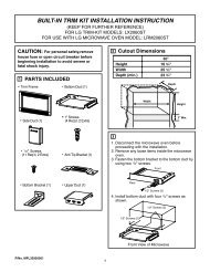
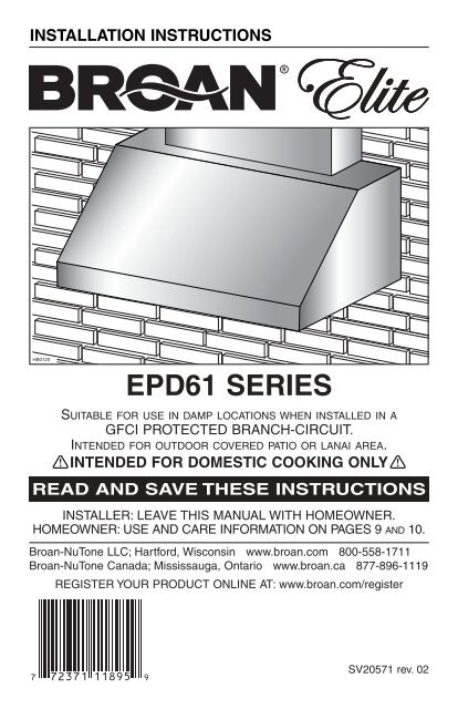
INSTRUCCIONES DE INSTALACIÓNHB0120SERIE <strong>EPD61</strong>ADECUADA PARA LUGARES HÚMEDOS CUANDO SE INSTALA EN UNCIRCUITO DE DERIVACIÓN PROTEGIDO CON UN DISYUNTOR.PREVISTA PARA PATIOS O TERRAZAS CUBIERTAS.! SÓLO PARA COCINA DOMÉSTICA !LEA Y CONSERVE ESTAS INSTRUCCIONESINSTALADOR: DEJAR ESTE MANUAL AL PROPIETARIO.PROPIETARIO: INFORMACIÓN SOBRE LIMPIEZA YFUNCIONAMIENTO EN LAS PÁGINAS 33 Y 34.<strong>Broan</strong>-NuTone LLC; Hartford, Wisconsin www.broan.com 800-558-1711<strong>Broan</strong>-NuTone Canada; Mississauga, Ontario www.broan.ca 877-896-1119REGISTRE SU PRODUCTO EN LÍNEA EN: www.broan.com/register<strong>SV20571</strong> <strong>rev</strong>. <strong>02</strong>
! ADVERTENCIA! ADVERTENCIAPARA REDUCIR EL RIESGO DE INCENDIO,DESCARGA ELÉCTRICA O LESIÓN CORPORAL,RESPETE LAS SIGUIENTES INDICACIONES:1. Utilice este aparato únicamente de la forma en queindica el fabricante. Si tiene cualquier pregunta,comunique con el fabricante en la dirección oteléfono que aparecen en la garantía.2. Antes de reparar o limpiar el aparato, apáguelo enel tablero de servicio y bloquee los medios dedesconexión para impedir que la corriente seconecte accidentalmente. Cuando no se puedabloquear los medios de desconexión, coloque undispositivo de advertencia visible (como unaetiqueta) en el tablero de servicio.3. La instalación y la conexión eléctrica deben serrealizadas por personal competente, de acuerdocon todos los códigos y normas aplicables, inclusolos relativos a la construcción ignífuga.4. Para lograr una combustión adecuada y unaextracción correcta de los gases a través de lasalida del humo (chimenea) del equipo quemadorde combustible —evitando así el contratiro— esnecesario disponer de aire suficiente. Siga lasdirectrices del fabricante del equipo de materialtérmico y las normas de seguridad, como las quepublica la NFPA (asociación de protección contralos incendios) y la ASHRAE (sociedadestadounidense de técnicos de calefacción,refrigeración y aire acondicionado) así como loscódigos de los organismos responsables locales.5. Cuando corte o taladre en una pared o techo, nodañe los cables eléctricos ni otras instalacionesocultas.6. Los ventiladores entubados deben tener salidasiempre al exterior.7. No utilice este aparato con un dispositivo decontrol de velocidad con semiconductores.8. Para reducir el riesgo de incendio, utilice sóloconductos en metal.9. Este aparato debe conectarse a tierra y ha deestar protegido con un disyuntor.10. Adecuado para lugares húmedos cuando se instalaen un circuito de derivación PROTEGIDO CON UNDISYUNTOR.11. Este aparato no está pensado para utilizarse con unaparrilla de carbón.12. Cuando una reglamentación local esta en vigor yconlleva exigencias de instalación y/o decertificación mas estrictas, susodichas exigenciasp<strong>rev</strong>alecen sobre aquellas en este documento y elinstalador acepta someterse a estas exigencias asus gastos.PARA REDUCIR EL RIESGO DE QUE ARDALA GRASA EN LA PARTE SUPERIOR DE LACOCINA:a) No deje nunca recipientes de cocina a fuego vivo sinvigilancia. Los desbordamientos producen humo yderrames grasientos que pueden inflamarse.Caliente el aceite despacio, a fuego lento o mediano.b) Ponga en marcha siempre la campana al cocinar atemperaturas elevadas o al cocinar alimentosflameados (por ejemplo: crepas Suzette, cerezasjubilee, res con pimienta flambeada).c) Limpie los ventiladores con frecuencia. No dejeque la grasa se acumule en el ventilador ni en losfiltros o en los conductos de evacuación.d) Utilice cacerolas de tamaño apropiado. Empleesiempre un recipiente adecuado para el tamaño dela placa.- 26 -PARA REDUCIR EL RIESGO DE LESIONESCORPORALES EN EL CASO DE QUE ARDALA GRASA EN LA PARTE SUPERIOR DE LACOCINA, SIGA ESTAS INDICACIONES*:1. SOFOQUE LAS LLAMAS con una tapa ajustada,una hoja o bandeja metálica para hornear galletas,y apague luego el quemador. TENGA CUIDADOPARA EVITAR QUEMADURAS. SI LAS LLAMASNO SE APAGAN INMEDIATAMENTE, EVACUE ELLUGAR Y LLAME A LOS BOMBEROS.2. NO SUJETE NUNCA UN RECIPIENTE ENLLAMAS ya que podría quemarse.3. NO USE AGUA, ni trapos o toallas húmedas.Podría causar una violenta explosión de vapor.4. Utilice un extintor SOLAMENTE si:A. Tiene un extintor de tipo ABC y sabe usarlo.B. El incendio es pequeño y está circunscrito a lazona donde empezó.C. Ya ha llamado a los bomberos.D. Puede tratar de apagar el fuego si disponesiempre de una salida detrás de usted.*Fuente: “Kitchen Fire Safety Tips” publicado por la NFPA.PRECAUCIÓN1. Sólo para ventilación general. No debe utilizarsepara extraer materiales o vapores peligrosos oexplosivos.2. Para evitar daños en el cojinete del motor y que lashélices hagan ruido o se desequilibren, mantenga launidad de alimentación lejos de los vaporizadoresde pirca, del polvo de la construcción, etc.3. El motor de la campana tiene un dispositivo contrasobrecargas térmicas que apaga el motorautomáticamente si éste se sobrecalienta. El motorvolverá a ponerse en marcha cuando se enfríe. Siel motor sigue apagándose y encendiéndose,haga examinar la campana.4. Para que la campana capte bien las impurezasque se desprenden al cocinar, la distancia mínimaentre la campana y la superficie de la cocina nodebe ser inferior a 36 pulgadas.5. Dado el tamaño y el peso de esta campana, seaconsejan dos personas para instalarla.6. Para reducir los riesgos de incendio y extraer elaire debidamente, el aire debe evacuarse fuera.No extraiga el aire a espacios situados entre lasparedes, en el techo o en el desván, falso techo ogaraje.7. Este producto está equipado con un termostatoque puede poner en marcha el ventiladorautomáticamente. Para reducir el riesgo de que seproduzcan daños y evitar poner en marcha laalimentación accidentalmente, apague la corrienteen el tablero de servicio, bloquee este tablero oponga una etiqueta de advertencia.8. Para mayor información y conocer los requisitos,lea la etiqueta con las especificaciones en elproducto.
- CAMPANAS DE COCINA DE LA SERIE <strong>EPD61</strong> -MODELO 441(CAPUCHÓN MURAL REDONDO DE 10")MODELO 437(CAPUCHÓN DE ALTACAPACIDAD PARA TEJADO)MODELO 418(CODO AJUSTABLEREDONDODE 10")MODELO 410(TUBO REDONDO DE 10",SECCIONES DE 2 PIES)SERIE AWEPD,EXTENSIÓN MURALOPCIONALSERIE AEEPD, CHIMENEADECORATIVA OPCIONALADAPTADOR REDONDO DE 10"(VIENE CON LA CAMPANA)CAMPANA DE LASERIE <strong>EPD61</strong>HL0186VENTILADORDOBLE (VIENECON LA CAMPANA)- 27 -
1. INSTALACIÓN DE LAS TUBERÍAS Y DEL CABLEADO ELÉCTRICOPRECAUCIÓNEsta campana está p<strong>rev</strong>ista para patios o terrazas exteriores cubiertos. Comoocurre con todos los aparatos eléctricos, se debe proteger esta campana todolo posible de la intemperie.! ADVERTENCIAEsta campana no está pensada para usar con una parrilla de carbón.Planifique el lugar y la forma en que instalará lastuberías. Un tubo recto y corto permitirá que lacampana funcione más eficazmente.Instale tubos, codos y capuchones para tejado de lostamaños adecuados. Conecte la tubería metálica alcapuchón y vaya retrocediendo hasta el lugar dondeinstalará la campana. Utilice cinta metálica de 2” parasellar las juntas.! ADVERTENCIAEl cable de alimentación debe ser un circuitode derivación protegido con un disyuntor.Lleve un cable de alimentación de tres hilos hasta ellugar de la instalación.Para que la campana capte bien las impurezasque se desprenden al cocinar, la distancia mínimaentre la campana y la superficie de la cocina nodebe ser inferior a 36 pulgadas.TUBO REDONDO DE 10"CHEMINEA DECORATIVAOPCIONAL O INTRÁDOSCODO REDONDO DE 10"18"16" HASTALA PARTE SUPERIORDE LA REGLETADE MONTAJE DE MADERADISTANCIA MÍNIMA DE36” SOBRE EL NIVEL DELA SUPERFICIE PARA COCINACAPUCHÓN DE TECHOCAPUCHÓNMURALADAPTADORREDONDODE 10"HH0182E2. PREPARACIÓN DE LA INSTALACIÓN! ADVERTENCIASe aconseja llevar lentes y guantes de seguridad para instalar, reparar o limpiarla campana.NOTA: Antes de comenzar la instalación, verificar el contenido de la caja. Si alguna pieza falta oestá dañada, póngase en contacto con el fabricante.Verifique que la caja contenga los siguientes elementos:- Campana- Regleta de madera (en la parte trasera de la campana)- <strong>Manual</strong> de instalación- Accesorios:• Filtros con manijas: 3 para el modelo de 36” de ancho y 4 para el modelo de 48” de ancho• Adaptador redondo de 10” (dentro de la campana)• Bolsa con piezas: 3 conectores impermeables de hilos, 2 tornillos n.° 8 x 5/8’’,6 tornillos de cabeza hexagonal n.° 10 x 2’’, 4 tornillos de cabeza plana n.° 10 x 2”,2 sujeciones murales, 2 arandelas 3/16’’ DI x 3/4’’ DELa bolsa debería incluir también las siguientes piezas que no deben usarse(deséchelas): 2 abrazaderas de hilos LP16-AP,2 tornillos n.° 8 x 3/8’’ <strong>rev</strong>estidos de zinc, 8 tornillos de acero inoxidable n.° 8 x 3/8”,4 tuercas de acero inoxidable 10-32, 4 arandelas 3/16’’ DI x 3/4’’ DE- 28 -
2. PREPARACIÓN DE LA INSTALACIÓN (CONTINUACIÓN)Piezas vendidas aparte:- Bombillas halógenas (120 V, 50 W máx., MR16 con base GU10) (2 para el modelo de 36” deancho y 3 para el modelo de 48” de ancho)- Chimenea decorativa para la serie AEEPD, se instala sobre la campana (opcional)- Extensión mural para la serie AWEPD, 36” o 48” de ancho (opcional)- Cambios de sección, tubos, codos, dispositivos de cierre, capuchones murales y de techoConsulte la página 27 para ver la lista completa de opciones de aireación y los números de modelo.NOTA: Proteja la encimera y la parte superior de la cocina durante la instalación.3. INSTALACIÓN DE LA EXTENSIÓN MURAL (OPCIONAL)Serie AWEPDLa extensión mural debe instalarse antes que la campana (vea las instrucciones que vienen conla extensión mural)4. PERFORACIÓN DEL ORIFICIOQuite el cierre del orificio para el cableado eléctricoen la parte trasera de la campana. Instale laabrazadera de hilos (viene en la bolsa de piezas).HR00735. EXTRACCIÓN DE LOS FILTROS Y DEL RIEL DE VERTIDO DE LA GRASAA. Retire la cinta de los filtros.Saque los filtros de la campana y póngalos aparte.NOTA: Se aconseja empezar por el o los filtros centrales.B. Retire la cinta del riel de vertido de la grasa (1).Saque el riel y póngalo aparte.1HD0471A- 29 -B
6. INSTALACIÓN DEL ADAPTADORSaque el adaptador de la campana.Utilice 2 tornillos galvanizados n.° 8 x 3/8” de la bolsade piezas para colocar el adaptador en la partesuperior de la campana. Selle todas las juntas concinta metálica para evitar las fugas de aire.UBICACIÓN DE LOS TORNILLOSHJ00697. INSTALACIÓN DE LA REGLETA DE MONTAJE (SI NO SE USA LA EXTENSIÓN MURAL)PRECAUCIÓNDado el peso de la campana, compruebe que la regleta de montaje esté sujeta atodos los montantes disponibles de la pared; no sujete la regleta sólo en elpanel mural.NOTA: Si la campana se instala con la extensión mural opcional, consulte la hoja de instruccionesque viene con la extensión mural para la ubicación de la regleta de montaje.1. Se necesita una estructura de apoyo adecuada para soportar el peso de la campana.Construya la estructura mural con madera de 2" x 4" como mínimo.2. Marque la ubicación del centro de la campana.3. Mida y marque sobre la pared una línea a nivel por encima de la superficie sobre la que se cocinapara colocar la regleta de montaje (véase la ilustración de la página 28). Instale puntos de bloqueode 2" x 4" entre los montantes donde pondrá la regleta. Consulte la ilustración de la derecha.4. Saque la regleta de montaje de la parte trasera de la campana.5. Coloque la regleta sobre la pared y fíjela a los montantes y puntos de bloqueo con los 4 tornillosde cabeza plana n.° 10 x 2" (incluidos en la bolsa de piezas).MontantesexistentesRegletade montajeParte trasera de la campanaBloqueode 2" x 4"14¼" 15 1 ⁄8"18"16"HD0482E- 30 -
8. INSTALACIÓN DE LA CAMPANAPRECAUCIÓN• Aunque no es recomendable, si los ventiladores deben ser retirados, reinstalarloscon la ayuda de las tuercas 10-32 incluídas en la bolsa de piezas (fuerza detorsión máxima de 20 libras).• Sujete la campana hasta que esté bien fijada a la regleta de montaje.Quite la tapa del compartimentoeléctrico. Introduzca el cableado en lacampana y apriete la abrazadera parasujetar el cableado.TAPA DEL COMPARTIMENTO ELÉCTRICOPonga la parte trasera de la campanacontra la regleta de montaje.Sujete un tubo redondo de 10” aladaptador.Fije la campana a la regleta demontaje con 4 tornillos de cabezahexagonal n.° 10 x 2” (para lacampana de 36’’ de ancho) o 6 tornillos(para la campana de 48’’ de ancho).Taladre a través de los orificios de laparte interior trasera de la campanaindicados dos orificios de 3/16” en elpanel mural para los dispositivos desujeción mural. A continuación, instaleambos dispositivos de sujeción muralcon los tornillos n.° 8 x 5/8’’ y con lasarandelas provistas.10. CONEXIÓN DEL CABLEADOHD0469HD0470- 31 -UBICACIÓN DE LOS TORNILLOSUBICACIÓN DE LOS DISPOSITIVOSDE SUJECIÓN MURAL9. INSTALACIÓN DE LA CHIMENEA DECORATIVA (OPCIONAL)Serie AEEPDConsulte las instrucciones que vienen con la chimenea decorativa.! ADVERTENCIARiesgo de choque eléctrico. La conexión eléctrica debe hacerla personalcompetente con arreglo a los códigos y normas en vigor. Antes de conectar loshilos, corte la alimentación en el tablero de servicio y bloquee los medios dedesconexión para impedir que la corriente se conecte accidentalmente.INSTRUCCIONES PARA LOS CONECTORES DE HILOS IMPERMEABLES:1. Pele 3/8 de pulg. de los hilos.2. Junte las puntas peladas o conductores.3. No las retuerza. Coloque los hilos pelados juntos, con los extremos a la misma altura. Si laparte pelada de uno de los hilos es más corta que la del otro, ponga ese hilo más alto.4. Gire el conector sobre los hilos empujando firmemente hasta que quede bien apretado. NOapriete demasiado.5. Al introducir los hilos en los conectores, puede que salgan restos de un producto para laobturación. Limpie el sobrante de este producto alrededor de los conductores. NO VUELVA AUTILIZAR LOS CONECTORES.
10. CONEXIÓN DEL CABLEADO (CONTINUACIÓN)Conecte el cable a la caja de cableado conlos conectores impermeables de hilos.Conecte el hilo NEGRO con el NEGRO, elBLANCO con el BLANCO y sujete el VERDEo pelado al tornillo de tierra.Vuelva a instalar la tapa de la caja de cableado.HE013811. REINSTALACIÓN DEL RIEL DE VERTIDO DE LA GRASA Y DE LOS FILTROSVuelva a instalar el riel de vertido de la grasa. Lailustración de la derecha muestra la manera deintroducir el riel de vertido de la grasa en lacampana.HD0472PRECAUCIÓNRetire la película protectora de plástico que cubre los filtros antes de instalarlos.Se aconseja instalar primero los filtros de los lados y, por último, el o los del centro.1. Introduzca un extremo del filtro en la ranura superior de la campana.2. Levante el otro extremo hacia el interior de la campana e introdúzcalo en el riel de vertido dela grasa.12HD0473- 32 -
12. SUSTITUCIÓN DE LAS BOMBILLASEsta campana debe utilizar bombillas halógenas protegidas de tipo MR16, de 120 V y 50 W conbase GU1 (no incluidas). (2 para el modelo de 36” de ancho y 3 para el modelo de 48” de ancho.)! ADVERTENCIANo tocar las bombillas durante o justo después de la utilización. Pueden causarquemaduras. Para p<strong>rev</strong>enir el riesgo de lesiones corporales, instale solamentebombillas halógenas protegidas. Nunca instalar una bombilla dicroica o noconcebida para luminarias empotradas o bombillas identificadas sólo para usoen dispositivos encerrados.1. Para quitar las bombillas, empuje suavementehacia arriba y gire en sentido antihorario paraliberar el casquillo de sus ranuras.2. Instale las bombillas nuevas colocando loscasquillos de las bombillas en sus ranuras, enlos portalámparas.3. Empuje suavemente hacia arriba y gire almismo tiempo en el sentido horario hasta que1 2 3HO0089queden bien afianzadas.NOTA: De ser necesario, utilice un guante de caucho para lavar los platos para sujetar mejor labombilla y sacarla.13. CUIDADOFiltrosLos filtros deben limpiarse con frecuencia. Utilice una disolución de detergente con agua templada.Lávelos con mayor frecuencia si su tipo de cocina genera más grasa (alimentos fritos o cocinacon wok). Retire los filtros empujándolos hacia la parte delantera de la campana y girándoloshacia abajo. Las placas de los filtros pueden lavarse en el lavavajillas. Deje que los filtros sequencompletamente antes de volver a instalarlos en la campana.Limpie los filtros totalmente metálicos en el lavavajillas con un detergente sin fosfato. El filtropodría descolorarse si se utiliza un detergente con fosfato o debido al tipo de agua, pero esto noafecta su funcionamiento. Este descoloramiento no estácubierto por la garantía.Riel de vertido de la grasaEl riel debe limpiarse con frecuencia. Sáquelo de la campana y límpielo con una disolución dedetergente con agua. Lávelo con mayor frecuencia si su tipo de cocina genera más grasa(alimentos fritos o cocina con wok). Deje que el riel seque completamente antes de volver ainstalarlo en la campana.Limpieza de los ventiladoresRetire los filtros para tener acceso los ventiladores. Limpie los ventiladores con un aspirador. Nolos sumerja en agua.Limpieza de la campanaLimpieza del acero inoxidable:Debe hacerse:• Limpiar regularmente las superficies con untrapo limpio humedecido con una mezcla deagua templada y jabón suave o detergentepara la vajilla.• Limpiar siempre en la dirección de las líneasoriginales de pulido del acero.• Enjuagar siempre con agua limpia (2 o 3 veces)después de limpiar. Seque completamente.• También puede utilizar un limpiador domésticoespecial para acero inoxidable.No debe hacerse:• Utilizar un estropajo de acero o aceroinoxidable u otro tipo de rasquetas paraquitar la suciedad resistente.• Utilizar limpiadores fuertes o abrasivos.• Dejar que la suciedad se acumule.• Dejar que el polvo del yeso u otros residuosde la construcción manchen la campana. Siefectúa obras de construcción o renovación,cubra la campana para que no se manche lasuperficie de acero inoxidable.Al escoger un detergente, evite:• Los limpiadores que contienen blanqueador (lejía), ya que dañarán el acero inoxidable.• Los productos que contengan cloruro, fluoruro, yoduro y bromuro, ya que deterioran lassuperficies rápidamente.• Los productos combustibles que se emplean para la limpieza, como acetona, alcohol, éter,benzol, etc., ya que son altamente explosivos y nunca deberían estar cerca de una cocina.- 33 -
14. FUNCIONAMIENTO1 2HC00591) BOTÓN DE CONTROL DE LA VELOCIDAD DEL VENTILADOR2) INTERRUPTOR DE LAS LUCES HALÓGENASVENTILADORUn botón giratorio con 4 posiciones (1) permite controlar el ventilador (Apagado – Velocidad baja– Velocidad intermedia – Velocidad alta).Gire el botón de control de velocidad en el sentido de las agujas del reloj para incrementar lavelocidad del ventilador y en sentido contrario para disminuirla.LUCES (HALÓGENAS)Utilice el interruptor oscilante (2) para encender y apagar las luces halógenas.HEAT SENTRYEsta campana está equipada con un termostato Heat Sentry. Este dispositivo pone en marchael ventilador cuando detecta un calor excesivo por encima de la superficie sobre la que se cocina.1) Si el ventilador está apagado, se pondrá en marcha en la velocidad baja.2) Si el ventilador ya está funcionando, la velocidad no cambiará.! ADVERTENCIAEl termostato HEAT SENTRY puede poner en marcha el ventilador cuando sobrela cocina hay fuego u otra fuente de calor excesiva, incluso si la campana estáapagada. En tal caso, es imposible apagar el ventilador con el interruptor. Paraapagarlo, utilice el interruptor de alimentación principal situado detrás de losfiltros, si puede hacerlo de manera segura.Cuando la temperatura baje a un nivel normal, el ventilador volverá a su configuración original.INTERRUPTOR DEALIMENTACIÓNPRINCIPALHD0467- 34 -
15. DIAGRAMA ELÉCTRICOTERMOSTATOHEAT SENTRYINTERRUPTORPRINCIPALOINTERRUPTORPRINCIPALNENEAB1 OFF234RAZNNERAZNNENBAZNEAZBNNERMGM120 VACLÍNEAHILO NEUTROTIERRANENENEINTERRUPTORDE LÁMPARAACÓDIGO DE COLORESBAABBBBBABNBAZNEAZBNNERMGMAAZBGMNNERAMARILLOAZULBLANCOGRISMARRÓNNARANJANEGROROJOLÁMPARA LÁMPARA LÁMPARAHE0137E16. GARANTÍAGARANTÍA LIMITADA DE UN AÑO DE LOS PRODUCTOS BROAN ELITE<strong>Broan</strong>-NuTone LLC (<strong>Broan</strong> NuTone) garantiza al consumidor comprador original de sus productos que dichosproductos carecen de defectos en los materiales o de mano de obra por un período de un año a partir de lafecha de compra original. NO EXISTEN OTRAS GARANTÍAS, EXPRESAS O IMPLÍCITAS, INCLUYENDO —AUNQUE SIN LIMITARSE A ELLAS — LAS GARANTÍAS IMPLÍCITAS, DE APTITUD O IDONEIDAD PARAUN PROPÓSITO PARTICULAR.Durante el período de un año, y a su propio criterio, <strong>Broan</strong>-NuTone reparará o reemplazará sin costo todoproducto o pieza que se considere defectuosa en condiciones normales de servicio y uso.ESTA GARANTÍA NO SE APLICA A LOS CEBADORES, TUBOS, BOMBILLAS HALÓGENAS Y INCANDESCENTES,A LOS FUSIBLES, FILTROS, TUBOS, CAPUCHONES PARA TEJADOS, CAPUCHONES MURALES YOTROS ACCESORIOS DE CANALIZACIÓN. Esta garantía no cubre: a) el mantenimiento y servicios normalesni b) ningún producto o pieza mal utilizados o que hayan sido objeto de mal uso, negligencia, accidente,mantenimiento o reparación inadecuados (por compañías distintas a <strong>Broan</strong>-NuTone), instalación defectuosa,o instalación no conforme a las instrucciones de instalación recomendadas.La duración de cualquier garantía implícita se limita a un periodo de un año, como se indica en la garantíaexpresa. Algunos estados o provincias no permiten limitaciones en cuanto al tiempo de expiración de unagarantía implícita, por lo que la limitación antes mencionada puede que no se aplique en su caso.LA OBLIGACIÓN DE BROAN-NUTONE DE REPARAR O REEMPLAZAR, CON ARREGLO A SU PROPIOCRITERIO, SERÁ EL ÚNICO RECURSO LEGAL DEL COMPRADOR CONFORME A ESTA GARANTÍA.BROAN-NUTONE NO SE HACE RESPONSABLE DE LOS DAÑOS ADICIONALES, CONSECUENTES OESPECIALES QUE SURJAN O ESTÉN RELACIONADOS CON EL USO O EL RENDIMIENTO DELPRODUCTO. Algunos estados o provincias no permiten la exclusión o limitación de daños adicionales oconsecuentes, por lo que la limitación o exclusión antes mencionada puede que no se aplique en su caso.Esta garantía le proporciona derechos legales específicos, aunque usted también puede tener otros derechos,que varían de un estado a otro, o de una provincia a otra. Esta garantía reemplaza todas las garantíasanteriores.Para tener derecho al servicio de garantía, debe usted: a) Informar a <strong>Broan</strong>-NuTone, a una de las direccioneso teléfonos que aparecen abajo; b) Dar el número de modelo y el número de identificación de la pieza y (c)Describir el tipo de defecto en el producto o pieza. En el momento de solicitar un servicio cubierto por la garantía,deberá presentar una prueba de la fecha de compra original.Estados Unidos - <strong>Broan</strong>-NuTone LLC; 926 W. State Street, Hartford, Wisconsin 53<strong>02</strong>7 www.broan.com800-558-1711Canadá - <strong>Broan</strong>-NuTone Canada; 1140 Tristar Drive, Mississauga, ON L5T 1H9 www.broan.ca 877-896-1119- 35 -
17. PIEZAS1SUSTITUCIÓN DE PIEZAS Y REPARACIÓN211910 78Para que la unidad se conserve en buenestado, debe usar repuestos genuinosde <strong>Broan</strong>-NuTone únicamente. Estaspiezas se han diseñado especialmentepara cada unidad y se han fabricadoconforme a las normas de certificaciónaplicables y un elevado nivel de seguridad.El uso de repuestos de otros fabricantespodría causar daños graves y reducirradicalmente el desempeño de launidad, causando así fallas prematuras.<strong>Broan</strong>-NuTone también aconseja ponerseen contacto con un taller de reparaciónhomologado por <strong>Broan</strong>-NuTone paratodos los repuestos y reparaciones.435HL01876N.°N.° DEPIEZA*NO SE MUESTRA.DESCRIPCIÓN- 36 -CTD (ANCHURA CAMPANA)36” 48”1 SV08541 ADAPTADOR REDONDO DE 10” 1 12 SV16569 CONJUNTO DE LA LÁMPARA 2 33 SV08582 VENTILADOR 2 24 SV08337 RESORTE DEL FILTRO 3 45 SV60675 FILTROS 11.84” X 15.125” (RESORTE INCLUSIVE) 3 46 SV60695 RIEL DE VERTIDO DE LA GRASA, 36”1-SV60696 RIEL DE VERTIDO DE LA GRASA, 48”-17 SV<strong>02</strong>563 INTERRUPTOR OSCILANTE DE LA LUZ 1 18 SV08095 BOTÓN DEL VENTILADOR 1 19 SV03435 TERMOSTATO HEAT SENTRY 1 110 SV08968 CONTROL DE LA VELOCIDAD 1 111 SV08548 INTERRUPTOR DE ALIMENTACIÓN PRINCIPAL 1 1* SV06750 LOGO DE BROAN ELITE 1 1* <strong>SV20571</strong> GUÍA DE INSTALACIÓN 1 1* SV04216BOLSA DE PIEZAS: 3 CONECTORES IMPERMEABLES DE HILOS,2 TORNILLOS N.° 8 X 5/8’’, 6 TORNILLOS DE CABEZA HEXAGONAL N.°10 X 2’’, 4 TORNILLOS DE CABEZA PLANA N.° 10 X 2”,2 SUJECIONES MURALES, 6 ARANDELAS 3/16’’ DI X 3/4’’ DE,4 TUERCAS DE ACERO INOXIDABLE 10-32, 2 ABRAZADERAS DEHILOS LP16-AP, 2 TORNILLOS N.° 8 X 3/8’’ REVESTIDOS DE ZINC,8 TORNILLOS DE ACERO INOXIDABLE N.° 8 X 3/8”1 1