Wiring Diagram
Wiring Diagram
Wiring Diagram
- No tags were found...

You also want an ePaper? Increase the reach of your titles
YUMPU automatically turns print PDFs into web optimized ePapers that Google loves.
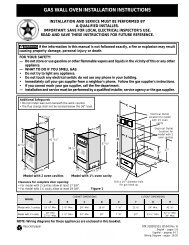
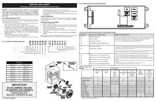
SERVICE DATA SHEETGas Ranges with ES 200/205/300 & 305 Electronic Oven ControlsELECTRONIC OVEN CONTROL (REAR VIEW)NOTICE - This service data sheet is intended for use by personshaving electrical and mechanical training and a level of knowledge ofthese subjects generally considered acceptable in the appliancerepair trade. The manufacturer cannot be responsible, nor assumeany liability for injury or damage of any kind arising from the use of thisdata sheet.SAFE SERVICING PRACTICESTo avoid the possibility of personal injury and/or property damage, it is importantthat safe servicing practices be observed. The following are examples, butwithout limitation, of such practices.1. Before servicing or moving an appliance remove power cord from electricaloutlet, trip circuit breaker to OFF, or remove fuse.2. Never interfere with the proper installation of any safety device.3. GROUNDING: The standard color coding for safety ground wires is GREENor GREEN WITH YELLOW STRIPES. Ground leads are not to be used ascurrent carrying conductors. It is extremely important that theservice technician reestablish all safety grounds prior tocompletion of service. Failure to do so will create a potentialsafety hazard.4. Prior to returning the product to service, ensure that:• All electric connections are correct and secure.• All electrical leads are properly dressed and secured away from sharpE.O.C. CONTROL CONNECTIONS (P5)edges, high-temperature components, and moving parts.• All uninsulated electrical terminals, connectors, heaters, etc. are adequatelyspaced away from all metal parts and panels.• All safety grounds (both internal and external) are correctly and securelyreassembled.OVEN CALIBRATIONSet the electronic oven control for normal baking at 350°F. Obtain an averageoven temperature after a minimum of 5 cycles. Press CANCEL or CLEAR toend bake mode.TEMPERATURE ADJUSTMENT1. Set EOC to bake at 550°F.2. Within 5 seconds of setting 550°F, press and hold the bake pad forapproximately 15 seconds until a single beep is heard (longer may causeF11 shorted keypad alarm).3. Calibration offset should appear in the display.4. Use the slew keys to adjust the oven temperature up or down 35°F in 5°Fincrements.5. Once the desired (-35° to 35°) offset has been applied, press CANCEL orCLEAR.Note: Changing calibration affects both Speed Bake and normal bake modes.The adjustments made will not change the self-cleaning temperature.ELECTRONIC OVEN CONTROL FAULT CODE DESCRIPTIONSFault CodeF10F11F12F13Likely Failure Condition/CauseRunaway Temperature.Shorted Keypad.Bad Micro Identification.Bad EEPROM Identification/Checksum error.Suggested Corrective Action1. (F10 only) Check RTD Sensor Probe & replace if necessary. If oven is overheating, disconnectpower. If oven continues to overheat when the power is reapplied, replace EOC. Severeoverheating may require the entire oven to be replaced should damage be extensive.2. (F11, 12 & 13) Disconnect power, wait 30 seconds & reapply power.3. (F11, 12 & 13) If fault returns upon power-up, replace EOC.F30F31Open probe connection.Shorted Probe connection.1. (F30 or F31) Check resistance at room temperature & compare to RTD Sensor resistance chart.If resistance does not match the RTD chart replace RTD Sensor Probe. Check Sensor wiringharness between EOC & Sensor Probe connector.2. (F30 or F31) Check resistance at room temperature, if less than 500 ohms, replace RTD SensorProbe. Check for shorted Sensor Probe harness between EOC & Probe connector.RTD SCALETemperature (°F) Resistance (ohms)RESISTANCETEMPERATUREDETECTORF90F91F92F93F94Maximum oven door unlock time exceeded.Maximum oven door unlock attempts exceeded.Maximum oven door open time exceeded.Maximum oven door lock time exceeded.Maximum oven door lock attempts exceeded.1. (F90, 91, 92, 93 & 94) Check the wiring between EOC & Lock Motor Micro Switch.2. (F90, 91, 92, 93 & 94) Replace the Motor Door Latch assembly if necessary.3. (F90, 91, 92, 93 & 94) Check for binding of the Latch Cam, Lock Motor Rod & Lock Motor Cam.4. (F90, 91, 92, 93 & 94) Check to see if Lock Motor Coil is open. If open, replace Lock MotorAssembly.5. (F90, 91, 92, 93 & 94) Lock Motor continuosly runs - if Micro Switch is open, replace Lock MotorAssembly.6. (F92, 93 & 94) Check oven door Light Switch - if open, replace Switch.7. If all situations above do not solve problem, replace EOC.32 ± 1.9 1000 ± 4.075 ± 2.5 1091 ± 5.3CIRCUIT ANALYSISMATRIX250 ± 4.4 1453 ± 8.9350 ± 5.4 1654 ± 10.8450 ± 6.9 1852 ± 13.5550 ± 8.2 2047 ± 15.8650 ± 9.6 2237 ± 18.5900 ± 13.6 2697 ± 24.4IMPORTANTDO NOT REMOVE THIS BAGOR DESTROY THE CONTENTSWIRING DIAGRAMS AND SERVICEINFORMATION ENCLOSEDREPLACE CONTENTS IN BAGp/n 316441736 (0612)
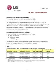
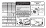
GENERAL TROUBLESHOOTING DIAGRAMGENERAL TROUBLESHOOTING SCHEMATIC