Circuits linéaires en régime sinusoïdal forcé I - Les CPGE de Loritz
Circuits linéaires en régime sinusoïdal forcé I - Les CPGE de Loritz
Circuits linéaires en régime sinusoïdal forcé I - Les CPGE de Loritz
- No tags were found...

Create successful ePaper yourself
Turn your PDF publications into a flip-book with our unique Google optimized e-Paper software.
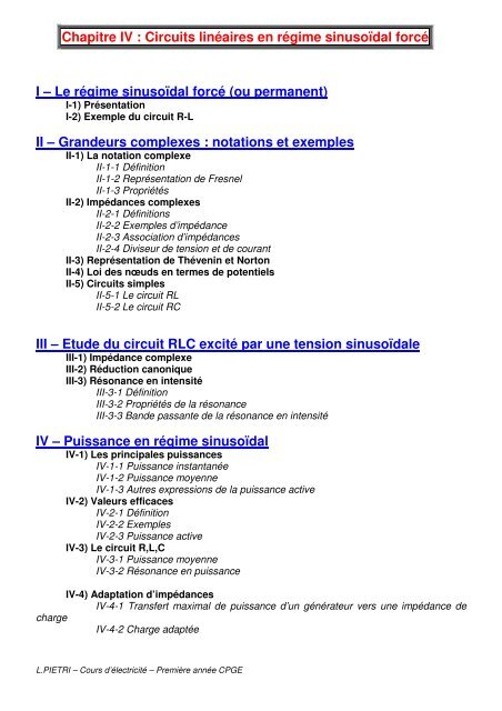
Chapitre IV : <strong>Circuits</strong> linéaires <strong>en</strong> régime sinusoïdal forcéI – Le régime sinusoïdal forcé (ou perman<strong>en</strong>t)I-1) Prés<strong>en</strong>tationI-2) Exemple du circuit R-LII – Gran<strong>de</strong>urs complexes : notations et exemplesII-1) La notation complexeII-1-1 DéfinitionII-1-2 Représ<strong>en</strong>tation <strong>de</strong> FresnelII-1-3 PropriétésII-2) Impédances complexesII-2-1 DéfinitionsII-2-2 Exemples d’impédanceII-2-3 Association d’impédancesII-2-4 Diviseur <strong>de</strong> t<strong>en</strong>sion et <strong>de</strong> courantII-3) Représ<strong>en</strong>tation <strong>de</strong> Thév<strong>en</strong>in et NortonII-4) Loi <strong>de</strong>s nœuds <strong>en</strong> termes <strong>de</strong> pot<strong>en</strong>tielsII-5) <strong>Circuits</strong> simplesII-5-1 Le circuit RLII-5-2 Le circuit RCIII – Etu<strong>de</strong> du circuit RLC excité par une t<strong>en</strong>sion sinusoïdaleIII-1) Impédance complexeIII-2) Réduction canoniqueIII-3) Résonance <strong>en</strong> int<strong>en</strong>sitéIII-3-1 DéfinitionIII-3-2 Propriétés <strong>de</strong> la résonanceIII-3-3 Ban<strong>de</strong> passante <strong>de</strong> la résonance <strong>en</strong> int<strong>en</strong>sitéIV – Puissance <strong>en</strong> régime sinusoïdalIV-1) <strong>Les</strong> principales puissancesIV-1-1 Puissance instantanéeIV-1-2 Puissance moy<strong>en</strong>neIV-1-3 Autres expressions <strong>de</strong> la puissance activeIV-2) Valeurs efficacesIV-2-1 DéfinitionIV-2-2 ExemplesIV-2-3 Puissance activeIV-3) Le circuit R,L,CIV-3-1 Puissance moy<strong>en</strong>neIV-3-2 Résonance <strong>en</strong> puissanceIV-4) Adaptation d’impédancesIV-4-1 Transfert maximal <strong>de</strong> puissance d’un générateur vers une impédance <strong>de</strong>chargeIV-4-2 Charge adaptéeL.PIETRI – Cours d’électricité – Première année <strong>CPGE</strong>
Chapitre IV : <strong>Circuits</strong> linéaires <strong>en</strong> régime sinusoïdal forcéIntroductionLe signal sinusoïdal est le signal utilisé pour déterminer les caractéristiques <strong>de</strong>s circuitslinéaires <strong>en</strong> régime forcé dans l’ARQS. La notation complexe, introduite à cette occasion peutapparaître au premier abord comme une complication inutile.En fait <strong>en</strong> se donnant une structure mathématique assez riche, les problèmes r<strong>en</strong>contrésse résolv<strong>en</strong>t <strong>de</strong> façon élégante, systématique et simple.Dans ce chapitre nous <strong>en</strong>visageons que <strong>de</strong>s circuits linéaires fonctionnant dans l’ARQS.L.PIETRI – Cours d’électricité – Première année <strong>CPGE</strong>
I – Le régime sinusoïdal forcé (ou perman<strong>en</strong>t)I-1) Prés<strong>en</strong>tationI-2) Exemple du circuit R-LL.PIETRI – Cours d’électricité – Première année <strong>CPGE</strong>
L.PIETRI – Cours d’électricité – Première année <strong>CPGE</strong>
L.PIETRI – Cours d’électricité – Première année <strong>CPGE</strong>
II – Gran<strong>de</strong>urs complexes : notations et exemplesII-1) La notation complexeII-1-1 DéfinitionII-1-2 Représ<strong>en</strong>tation <strong>de</strong> FresnelII-1-3 PropriétésL.PIETRI – Cours d’électricité – Première année <strong>CPGE</strong>
II-2) Impédances complexesII-2-1 DéfinitionsII-2-2 Exemples d’impédanceL.PIETRI – Cours d’électricité – Première année <strong>CPGE</strong>
II-2-3 Association d’impédancesII-2-4 Diviseur <strong>de</strong> t<strong>en</strong>sion et <strong>de</strong> couranta) diviseur <strong>de</strong> t<strong>en</strong>sionL.PIETRI – Cours d’électricité – Première année <strong>CPGE</strong>
) diviseur <strong>de</strong> courantII-3) Représ<strong>en</strong>tation <strong>de</strong> Thév<strong>en</strong>in et NortonII-4) Loi <strong>de</strong>s nœuds <strong>en</strong> termes <strong>de</strong> pot<strong>en</strong>tielsL.PIETRI – Cours d’électricité – Première année <strong>CPGE</strong>
II-5) <strong>Circuits</strong> simplesII-5-1 Le circuit RLL.PIETRI – Cours d’électricité – Première année <strong>CPGE</strong>
II-5-2 Le circuit RCL.PIETRI – Cours d’électricité – Première année <strong>CPGE</strong>
III – Etu<strong>de</strong> du circuit RLC excité par une t<strong>en</strong>sion sinusoïdaleIII-1) Impédance complexeIII-2) Réduction canoniqueL.PIETRI – Cours d’électricité – Première année <strong>CPGE</strong>
L.PIETRI – Cours d’électricité – Première année <strong>CPGE</strong>
III-3) Résonance <strong>en</strong> int<strong>en</strong>sitéIII-3-1 DéfinitionIII-3-2 Propriétés <strong>de</strong> la résonanceL.PIETRI – Cours d’électricité – Première année <strong>CPGE</strong>
III-3-3 Ban<strong>de</strong> passante <strong>de</strong> la résonance <strong>en</strong> int<strong>en</strong>sitéL.PIETRI – Cours d’électricité – Première année <strong>CPGE</strong>
IV – Puissance <strong>en</strong> régime sinusoïdalIV-1) <strong>Les</strong> principales puissancesIV-1-1 Puissance instantanéeIV-1-2 Puissance moy<strong>en</strong>nea) Moy<strong>en</strong>ne temporelleb) Puissance activeL.PIETRI – Cours d’électricité – Première année <strong>CPGE</strong>
c) Expressions du facteur <strong>de</strong> puissanceL.PIETRI – Cours d’électricité – Première année <strong>CPGE</strong>
IV-1-3 Autres expressions <strong>de</strong> la puissance activeL.PIETRI – Cours d’électricité – Première année <strong>CPGE</strong>
IV-2) Valeurs efficacesIV-2-1 DéfinitionIV-2-2 Exemples• int<strong>en</strong>sité efficace• T<strong>en</strong>sion efficace• Signaux redressésL.PIETRI – Cours d’électricité – Première année <strong>CPGE</strong>
IV-2-3 Puissance activeIV-3) Le circuit R,L,CIV-3-1 Puissance moy<strong>en</strong>neOn a vu que ℘=R(ω)I² par conséqu<strong>en</strong>t :• ℘ R =RI²• ℘ C =0• ℘ L =0Or pour un circuit R,L,C série on a u=u R +u L +u C ⇒ ℘=℘ R +℘ L +℘ C =RI²Par conséqu<strong>en</strong>t <strong>en</strong> régime transitoire on a P=e(t).i(t)=d/dt(Li²+q²/C)+Ri² alors qu’<strong>en</strong>régime sinusoïdal la seule puissance moy<strong>en</strong>ne non nulle c’est l’effet Joule.IV-3-2 Résonance <strong>en</strong> puissance2ImaxRImaxPmaxOn a vu que I=⇒ ℘==1 + Q²( x −1/ x)²1 + Q²( x − 1/ x)² 1 + Q²( x −1/ x)²On a donc résonance pour x=1 comme pour la résonance <strong>en</strong> int<strong>en</strong>sité, <strong>de</strong> plus la ban<strong>de</strong>passante étant défini par I max /√2
IV-4)Adaptation d’impédancesIV-4-1 Transfert maximal <strong>de</strong> puissance d’un générateur vers une impédance <strong>de</strong>chargeL.PIETRI – Cours d’électricité – Première année <strong>CPGE</strong>
IV-4-2 Charge adaptéemaximal <strong>de</strong> puissance <strong>en</strong>tre lé générateur et le quadripôle, souv<strong>en</strong>t on utilise <strong>de</strong>stransformateurs.L.PIETRI – Cours d’électricité – Première année <strong>CPGE</strong>
III–2) Réduction canonique :où Z(x)/R=√[1+Q²(x-1/x)²] et ϕ(x)=Arctan[Q(x-1/x)]III–3) Résonance <strong>en</strong> int<strong>en</strong>sité :III-3-1) Définitionoù i m (x)/[e m /R]=1/√[1+Q²(x-1/x)²] et ϕ i (x)=φ=-Arctan[Q(x-1/x)]III-3-2) Propriétés <strong>de</strong> la résonance<strong>Les</strong> graphes <strong>de</strong> i m (x)/[e m /R] et <strong>de</strong> ϕ i (x) <strong>en</strong> fonction <strong>de</strong> x, pour différ<strong>en</strong>tes valeurs <strong>de</strong> Q sont donnés dans lesdocum<strong>en</strong>ts 3 et 4. De leur exam<strong>en</strong> nous <strong>en</strong> déduisons les remarques suivantes :- Pour x = 1, l'amplitu<strong>de</strong> i m (x) <strong>de</strong> l'int<strong>en</strong>sité passe par un maximum i r =e m /R, quelle que soit la valeur du facteur<strong>de</strong> qualité Q du circuit. Il y a résonance d'int<strong>en</strong>sité.- à la résonance (ω=ω 0 ) le courant et la t<strong>en</strong>sion sont <strong>en</strong> phase : φ=0.- la résonance est d'autant plus aiguë que le circuit est plus faiblem<strong>en</strong>t amorti. (R plus faible où Q=Lω 0 /R plusélevé).- l'ess<strong>en</strong>tiel <strong>de</strong> la rotation <strong>de</strong> phase s'effectue au voisinage <strong>de</strong> la résonance et cette rotation est d'autant plusrapi<strong>de</strong> que l'amortissem<strong>en</strong>t est faible (Q»1).- la réponse i (t) est <strong>en</strong> avance sur l'excitation e (t) quand x1.- Quand la pulsation ω varie <strong>de</strong> zéro à l’infini, le déphasage passe <strong>de</strong> π/2 à - π/2, ce qui correspond à unerotation <strong>de</strong> phase <strong>de</strong> π.L.PIETRI – Cours d’électricité – Première année <strong>CPGE</strong>