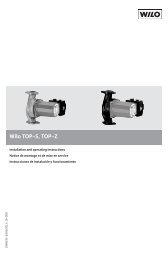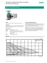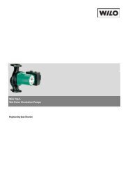
Wilo-TOP-S, TOP-Z - Wilo Canada Inc.
Wilo-TOP-S, TOP-Z - Wilo Canada Inc.
Wilo-TOP-S, TOP-Z - Wilo Canada Inc.
- No tags were found...

You also want an ePaper? Increase the reach of your titles
YUMPU automatically turns print PDFs into web optimized ePapers that Google loves.
xENGLISHIt is recommended that isolation valves be installed on the suction and discharge side of thepump.This will save having to drain and refill the system if the pump needs replacing. The valves areto be installed so that any water that escapes cannot drip onto the pump motor or terminal box.xAn arrow on the pump housing indicates the direction of water flow (Fig. 3, Pos. 1).xPump must be installed with the shaft in the horizontal position in such a way that it is notstressed by the pipework (Installation positions in Fig. 2).xIt is recommended that pressure gages be installed in the suction and discharge volute flanges(Fig.1b, Pos.2) to check pump and system performance.xIn order to obtain the correct terminal box position the motor housing can be turned after removingthe four allen screws (Fig. 4).WARNING!If the pump is already installed in the system, the system must be drained or the isolatingvalves on both sides of the pump must be closed before the allen screws areremoved as the pumped liquid may be scalding hot and/or under pressure.Do not start the pump until the system has been filled with liquid and vented.xPermitted terminal box positions see Fig. 2CAUTION! Possible damage of the pump!When rotating the motor housing, ensure the O-ring between the cartridge andpump housing (volute) does not become damaged.xxCarefully lift the pump head and rotate it so that the terminal box is in the desired position.Replace the pump head onto the pump housing and thighten the allen screws evenly in a diagonalmethod.Torque to: M6 ……. 17 ft lbM10 ……. 22 ft lbM12 ……. 45 ft lbxAfter replacing, check that the rotor shaft still rotates freely.<strong>TOP</strong>-S and <strong>TOP</strong>-Z pumps which are equipped with vent screws can be checked as follow (Fig.1a, Pos.9): Remove the plug (located in the middle of the rating plate), insert a flat headscrewdriver into the slot end of the shaft and turn to ensure free rotation.<strong>TOP</strong>-S and <strong>TOP</strong>-Z pumps without vent screws and not installed can be checked as follows:Insert a long screwdriver in the discharge port of the pump body (Fig.1, Pos.4) until you canfeel the impeller and rotate it with the tool. If the impeller does not turn easily, repeat the dis -assembly / reassembly process.Between the stator housing and pump volute, there are three drain holes to allow condensedwater to escape (Fig. 3, Pos. 2).CAUTION! Possible damage of the pump!The motor and condensate holes must remain free.For units which are to be insulated, only the pump volute may be insulated.7.2 Electrical connectionWARNING! Electrical shock hazardDangers caused by electrical energy must be excluded.xElectrical work by a qualified electrician only!xNational Electrical Codes, local codes and regulations must be strictly followed.xAll electrical connections must be performed after the electrical supply has beenswitched off and secured against unauthorized switching.xFor safe installation and operation a proper grounding of the pump to the powersupply’s grounding terminals is required.xSuitable fused overload protection is required to protect the motor per local electrical codes.7