Wilo-TOP-S, TOP-Z - Wilo Canada Inc.
Wilo-TOP-S, TOP-Z - Wilo Canada Inc.
Wilo-TOP-S, TOP-Z - Wilo Canada Inc.
- No tags were found...

Create successful ePaper yourself
Turn your PDF publications into a flip-book with our unique Google optimized e-Paper software.
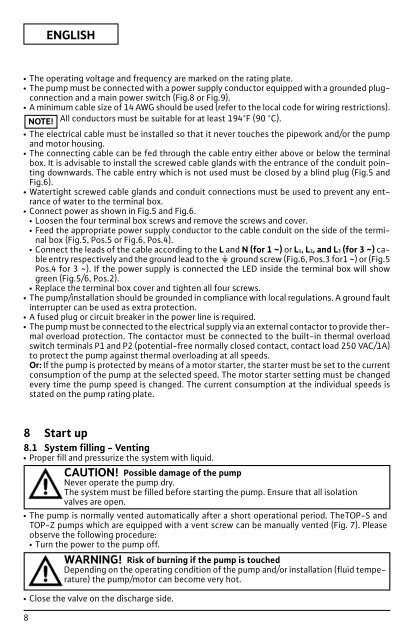
xENGLISHxxxxxxxxxThe operating voltage and frequency are marked on the rating plate.The pump must be connected with a power supply conductor equipped with a grounded plugconnectionand a main power switch (Fig.8 or Fig.9).A minimum cable size of 14 AWG should be used (refer to the local code for wiring restrictions).NOTE! All conductors must be suitable for at least 194°F (90 °C).The electrical cable must be installed so that it never touches the pipework and/or the pumpand motor housing.The connecting cable can be fed through the cable entry either above or below the terminalbox. It is advisable to install the screwed cable glands with the entrance of the conduit pointingdownwards. The cable entry which is not used must be closed by a blind plug (Fig.5 andFig.6).Watertight screwed cable glands and conduit connections must be used to prevent any entranceof water to the terminal box.Connect power as shown in Fig.5 and Fig.6.xLoosen the four terminal box screws and remove the screws and cover.xFeed the appropriate power supply conductor to the cable conduit on the side of the terminalbox (Fig.5, Pos.5 or Fig.6, Pos.4).xConnect the leads of the cable according to the L and N (for 1 ~ ) or L1, L2, and L3 (for 3 ~ ) cableentry respectively and the ground lead to the ground screw (Fig.6, Pos.3 for1 ~ ) or (Fig.5Pos.4 for 3 ~ ). If the power supply is connected the LED inside the terminal box will showgreen (Fig.5/6, Pos.2).xReplace the terminal box cover and tighten all four screws.The pump/installation should be grounded in compliance with local regulations. A ground faultinterrupter can be used as extra protection.A fused plug or circuit breaker in the power line is required.The pump must be connected to the electrical supply via an external contactor to provide thermaloverload protection. The contactor must be connected to the built-in thermal overloadswitch terminals P1 and P2 (potential-free normally closed contact, contact load 250 VAC/1A)to protect the pump against thermal overloading at all speeds.Or: If the pump is protected by means of a motor starter, the starter must be set to the currentconsumption of the pump at the selected speed. The motor starter setting must be changedevery time the pump speed is changed. The current consumption at the individual speeds isstated on the pump rating plate.8 Start up8.1 System filling - VentingxxxProper fill and pressurize the system with liquid.CAUTION! Possible damage of the pumpNever operate the pump dry.The system must be filled before starting the pump. Ensure that all isolationvalves are open.The pump is normally vented automatically after a short operational period. The<strong>TOP</strong>-S and<strong>TOP</strong>-Z pumps which are equipped with a vent screw can be manually vented (Fig. 7). Pleaseobserve the following procedure:xTurn the power to the pump off.WARNING! Risk of burning if the pump is touchedDepending on the operating condition of the pump and/or installation (fluid temperature)the pump/motor can become very hot.8Close the valve on the discharge side.