Wilo-TOP-S, TOP-Z - Wilo Canada Inc.
Wilo-TOP-S, TOP-Z - Wilo Canada Inc.
Wilo-TOP-S, TOP-Z - Wilo Canada Inc.
- No tags were found...

Create successful ePaper yourself
Turn your PDF publications into a flip-book with our unique Google optimized e-Paper software.
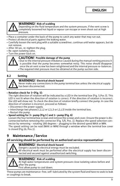
xENGLISHxxxxxWARNING! Risk of scaldingDepending on the fluid temperature and the system pressure, if the vent screw iscompletely loosened hot liquid or vapour can escape or even shoot out at highpressure.Place a container under the back of the pump to catch any water that may run out.Protect all electrical parts against the leaking water.Carefully loosen the vent plug with a suitable screwdriver, continue until water appears, but donot remove.After 30 sec. re-tighten the plug.Re-open isolating valve.Turn the power back on.CAUTION! Possible damage of the pumpxDue to the internal pressure imbalance caused during the manual venting process itis possible that the pump becomes somewhat noisy. This noise should disappearonce the air vent screw has been retightened and the internal pressure re-balances.xThe required inlet pressure must be obtained at the pump suction side.8.2 SettingWARNING! Electrical shock hazardNever make any connections in the pump terminal box unless the electrical supplyhas been disconnected.xRotation check for 3 ~ (Fig. 5):The right direction of rotation will be indicated by a LED in the terminal box (Fig. 5,Pos 3). ThisLED is not lit when the direction of rotation is correct. If the direction of rotation is incorrect,the LED will show red. To check the direction of rotation briefly connect the pump. In case thedirection of rotation is incorrect, proceed as follows:xDisconnect the power supply.xInterchange two phases( L1,L2 or L2,L3 or L1,L3) inside the terminal box.xRestart the pump.xSpeed setting for 3 ~ pump (Fig.5 ) and 1 ~ pump (Fig. 6)Loosen the four terminal box screws and remove the screws and cover. Ensure the power is dis -connected before removing the connector (Fig. 5/6, Pos. 1). Replace the speed selection connectorby removing - rotating 180 degrees - plugging to the desired speed MAX or MIN.The speed setting can be read (MAX or MIN) through a window when the terminal box coveris closed (Fig.1b, Pos.1).9 Maintenance / ServiceAll servicing should be performed by an authorized service representative!WARNING! Electrical shock hazardDangers caused by electrical energy must be excluded.All electrical work must be performed after the electrical supply has been disconnectedand secured against unauthorized switching.WARNING! Risk of scaldingAt high water temperatures and system pressure close isolating valves before andafter the pump.First allow pump to cool down.These pumps are maintenance-free, self-lubricated by the system fluid and have no seals to leakor couplings to break.9