• Installation InstructionsPlease read these instructions carefully prior toinstallation!Installation should only be carried out by personsqualified to do so!Incorrect installation can put the safety of persons atrisk!In case of improper installation, the manufacturer’sguarantee becomes void.Preparing for installation1. In order to allow mains connection, a socketmust be available on site - the supplied mainsconnecting cable has a length of 80 cm.2. Check the stability of the door. Retighten thescrews and nuts on the door.3. Check if the door is running smoothly. Lubricateshafts and bearings. Check the petension of thesprings and if necessary re-adjust.4. Establish the door’s highest point of travel (seefigure 6).5. Close the door and disable any existing locksout of operation, if necessary dismantle.Parts of latching devices, which couldform pinch or shear points, have to bedismantled.6. For garages without a second entrance, anemergency release is required (accessory).7. If a wicket pass door is included, fit the wicketdoor contact.0 The following tools are required- Drilling machine with10 mm masonry drill4 mm metal drill- Metal saw- Spanner, sizes 10 and 13 mm- Slotted screwdriver, width 3 mm- Phillips screwdriver, size 2 x 100- Spirit levelAttention: Check the supplied screws and wallplugs prior to use to ensure that these are suitable forthe strctural conditions on site.1 Supply package = complete setItems 2-9arepre-assembled1. Operator head including LED module2. Chain sprocket3. Track, operator side4. Carriage5. Toothed belt or chain6. Deflection roller7. Connector8. Track, door side9. Tensioner10. Wall bracket11. Door connector attachment12. Linking bar13. Central support14. Bag of screws15. Hand transmitter16. Support straps17. Telescopic fitting for sectional doors(accessory)2 Overview3 TrackAssemble the track as shown in the images 3a - 3b.44 Fastening the track to operator headSlot track (as illustrated) with chain sprocket (2) ontothe operator shaft (1a) and screw down with the 4self-tapping screws.5Fitting the connector attachment5a The enclosed door connector attachment issuitable for all Novoferm up-and-over doors andNovoferm ISO20 sectional doors.Position door connector attachment (11) centrally onthe top edge of the door leaf.Mark fixing holes and drill using 4 mm metal drill(max. Drilling depth 10 mm) or use the existing drillholes. Screw on attachment using enclosed selftappingscrews 6.3 x 16 (4 - 6 screws up-and-overdoor, 6 screws - ISO20).5b For other sectional doors, use telescopic fitting(17) (accessory).6 Attaching the wall bracketIn order to ensure that the door can run freelyunderneath the track, distance “x” must be greaterthan 20 mm. Choose distance “x” so that the angle ofthe linking bar does not exceed 45° (see figure 11).Mark the door’s highest point of travel “a” plusdistance “x” on the lintel.Hold wall fastening (10) at the total height (”a” + “x”)vertically over the door connector attachment drill,drill holes for wall plugs and screw the wall bracketonto the wall.7 Suspending the boom from the ceilingAttach central support (13) to track (8) in front of theconnector (7).8 Support strapsPositioning the prefitted operator at an angle to thedoor, screw to wall bracket (10). Lift up operator,making sure that it cannot fall down, and align in sucha way that the track runs horizontal and parallelbetween the door tracks.9 Establish the length of the support straps for theoperator head and the central support. If necessary,shorten using a saw, and then screw in place.Note: Before starting any drilling, cover over trackand operator head to protect them from drilling dust.Mark fixing points on the ceiling, drill 10 mm holes forplugs and screw on support straps.10 If the toothed belt or chain appear to be too slack,slight retensioning may be required. It may benecessary to take up the slack by adjusting thesupport straps.11 Connecting the door connector attachmentto the carriagePlace linking bar (12) between carriage (4) and thedoor connector attachment (11) and connect at bothends with the bolts. Provide bolts with security clips.Attach security clips to bolts.12 Disengaging the carriageIn order to carry out further work, it may be necessaryto disconnect the operator from the door by pullingthe pull cord on carriage (4) and move the doormanually.Note: If the door is to be operated manually for alonger period of time, then the locking pin must beremoved from parking position (a) on the left and withtheopull cord in locking position (b).GBremoved from parking position (a) on the left and withtheopull cord in locking position (b).In order to relock, return the locking pin into theparking position (a) on the left and restore theconnection between the operator and the door. Onthe next movement, the carriage automatically reengages.13 Aligning the aerial / Connecting planNote:It is essential to pull out the mains plug13 before opening the cover!Do not connect any live leads, only connectpotential-free buttons and potential-freerelay outputs. Finally, replace the cover andscrew down.Before using the operator for the firsttime, it must be tested to make sure that itis working properly and safely (seesection on Maintenance/Checks).E. Connecting the aerialWhen using an external aerial, the shieldingmust be assigned to the adjacent terminal (F, onright) 13b.F. Connection for external impulse generator(accessory, e. g. key switch or digital coder) 13bG.Input STOPAAbreak at this input end causes the operator tostop or prevents it from starting up.Connection for wicket door contact 13c(accessory)H. Connection for 2-wire photocell EXTRA626 13d(accessory).O.LED module• Impulse generators and external safety devicesIn case of increased need for personal safety, inaddition to the operator’s internal force limit, werecommend installing a one-way photocell. Furtherinformation on our range of accessories can befound in our sales literature. Consult your specialistdealer.• Warning stickerPlace the sticker clearly visible on the inner surfaceof the door.• Dismantling the operator1. Pull out the mains plug and disconnect all existingterminals.2. Disconnect door and operator. Fix door.3. Proceed according to points 3 to 14 of theinstallaton Instructions but in reverse sequence.Retain these installation, operating and maintenance instructions for the full duration of the operator’s service life!
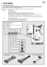
GB• Programming the operator14 Control elementsThe controls for programming the door operator areprotected by a transparent cover. The transparentcover can be opened with a screwdriver. After theoperator has been programmed, the transparentcover must be closed again.A. Numerical display shows the menu stage as wellas the selected value.a. Point display, lights up to indicate “ready foroperation” and flashes on the hand transmittercode learning completion.B. Button during the setting / adjustment phaseserves as an “up” button and outside the menu asa start button.C. Button during the setting /adjustment phaseserves as a “down” button.D. Button is used to call up the setting/adjustmentmenu, to change the menu stages and to store thesettings.The programming of the control unit is menu-driven.By pressing button , the menu guide is called up.The numbers displayed indicate the menu stage.After approx. 2 seconds, the display flashes and thesetting can be altered via buttons and . Theselected setting is stored with button . And theprogramme jumps automatically to the next menustage. By repeatedly pressing button , menustages can be skipped. To quit the menu, pressbutton until “0” is shown again. Outside the menu,button can be used to generate a start impulse.Before programming- Allow door to engage into the carriage.- Pull out the mains plug. Point display (a) lights up.- Make sure that the aerial is correctly positioned(see figure 13).- Observe the hand transmitter instructions.15 Menu stage 1: Programming the startfunction for the hand transmitterBriefly press button . “1” is displayed. As soon asthe display flashes, press and keep pressed forapprox. 1 second the button of the hand transmitter,with which you later wish to start the operator. As 20 Checking the force limit facilitysoon as the code has been read, the red point - Place an obstruction (e. g. operator’s cardboarddisplay (a) flashes five times before quitting. Figure 0 box) underneath the doors’s closing edge.will be displayed. Menu finished.- Starting from the OPEN end-of-travel position,Further hand transmitters (up to a maximum of 30) actuate the door to close.can be programmed.- The door travels towards the obstruction, stops1619and travels back to the top end-of-travel position.Menu stage 2: Programming the lightfunction for the hand transmitter(Not possible with TX43-2.)Press key briefly and figure 1 will be displayed.Press key once again and figure 2 will bedisplayed.Press the second button at the transmitter with whichthe 4-min light is to be switched on. As soon as thecode has been read in, the red point display (a) willflash 5 times to acknowledge the entry. Figure 0 willbe displayed. Menu finished.Deleating all the hand transmitters programmedfor the operator:Plug in the operator‘s main plug while pressingbutton .17 Menu stage 3: Setting/adjusting the top endof-travelpositionKeep button pressed for 3 seconds. Number 3appears in the display 8 a.Wait a short while until the 3 starts flashing.Press button and make sure that the door travels inthe OPEN direction.If the door closes in the wrong direction, afterhaving pressed , keep button pressed for!another 3 seconds. “3” flashes briefly. Thetravelling direction is altered.Now travel by pressing button into the desired doorend position OPEN 17b.By pressing button , the position can be correctedinto direction CLOSE.Once the desired OPEN end-of-travel position hasbeen reached, press button . The operator storesthe OPEN end-of-travel position and “4” appears inthe display.18 Menu stage 4: Setting/adjusting the bottomend-of-travel positionWait a short while until “4” starts flashing.Press button . The operator causes the door totravel in the CLOSE direction as long as the button ispressed. The position can be altered to the OPENdirection via button ..Once the desired CLOSE end-of-travel position hasbeen reached, press button . The operator storesthe CLOSE end-of-travel position and “5” appears inthe display.Press button twice until “0” appears.19 Force-learning cycleWe recommend setting the suitable door type inmenu stage 8 prior to the force-learning cycle.!During this opening and closing cycle, theoperator learns the force required to open and closethe door. A force limit does not apply! The cyclesmust not be interrupted. During these cycles mustnot be interrupted. During these cycles “0” appearsin the display.- Press button . The operator causes the door toopen until the top end-of-travel position has beenreached.- Now press button again. The operator causesthe door to close until the bottom end-of-travelposition has been reached.- After approx. 2 seconds, “0”disappears.If the door springs have been changed or altered,then the force learning cycle must be repeated:proceed to menu stage 5 and keep buttonpressed for 3 seconds. “0” appears in the display.Then complete the force learning cycle as explainedunder point 19.• Special settingsIn order to access the menus for the special settings,keep key pressed for 3 sec until figure 3 isdisplayed. Press key to by-pass menu step 3.Now keep key pressed for 3 sec until figure 5 isdisplayed. Press key to by-pass menu steps.Menu stage 5: The opening force limitIf you have previously quit the setting menu, pressbutton for 3 seconds until “3” appears. Then pressbutton twice until “5” appears.After approx. 2 seconds, the display flashes showingthe set value of the opening force limit. The force limitsetting can be increased for decreased via buttonsand .After setting the value, press button .The display shows “6”.Menu stage 6: The closing force limitAfter approx. 2 seconds, the display starts flashing,and the set value for the closing force limit isdisplayed.The force limit setting can be increased or decreasedvia buttons and .After setting the value, press button . “0” appearsin the display.Finally, check the force settings, and, if necessary,repeat the setting procedure.The maximum force at the main closing edge mustnot exceed 150 N!Caution! If the force setting is too high, persons maybe placed at risk of injury.The factory setting is 4!Menu stage 7: Light phasesKeep button pressed again for 3 seconds until“7” appears in the display.Menu Light Warning Flashingvalue phase phase function0 60s - -1 120 s - -2 240 s - -3 0 s - yes4 0 s 3 s -5 60s 3s -6 120 s 3 s yes7 60s 0s -8 120 s 0 s yes9 240 s 0 s yesWhen the advance warning time is set, the light willbe switched on before the drive starts running. Thefactory setting is 1.Menu stage 8: Door fittingPress button . “8” appears in the display.Menu Start Stop Start Stopvalue open open closed closed0 0 0 0 01 15 0 15 02 0 15 0 403 15 15 15 354 25 30 25 405 15 15 15 556 15 15 15 157 35 35 65 458 55 15 15 1009 only soft runThese values correspond to the “soft” runsmeasured in cm at the carriage.Important note:The factory setting of 4 must be adhered. Thesoftruns may only be alerted on the express permissionof the door manufacturer.Press button . “0” appears in the display.Retain these installation, operating and maintenance instructions for the full duration of the operator’s service life!


