ventilconvettore con inverter fan coil with inverter ventilo-convecteur ...
ventilconvettore con inverter fan coil with inverter ventilo-convecteur ...
ventilconvettore con inverter fan coil with inverter ventilo-convecteur ...

Create successful ePaper yourself
Turn your PDF publications into a flip-book with our unique Google optimized e-Paper software.
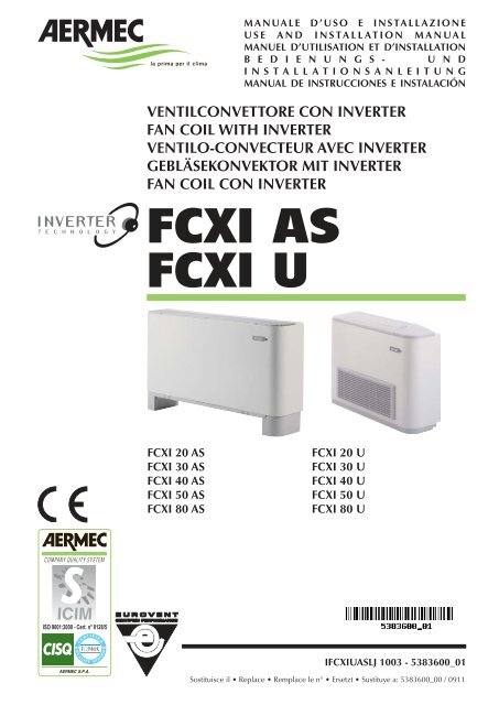
FCXI 20 AS<br />
FCXI 30 AS<br />
FCXI 40 AS<br />
FCXI 50 AS<br />
FCXI 80 AS<br />
MANUALE D’USO E INSTALLAZIONE<br />
USE AND INSTALLATION MANUAL<br />
MANUEL D’UTILISATION ET D’INSTALLATION<br />
B E D I E N U N G S - U N D<br />
INSTALLATIONSANLEITUNG<br />
MANUAL DE INSTRUCCIONES E INSTALACIÓN<br />
VENTILCONVETTORE CON INVERTER<br />
FAN COIL WITH INVERTER<br />
VENTILO-CONVECTEUR AVEC INVERTER<br />
GEBLÄSEKONVEKTOR MIT INVERTER<br />
FAN COIL CON INVERTER<br />
FCXI AS<br />
FCXI U<br />
FCXI 20 U<br />
FCXI 30 U<br />
FCXI 40 U<br />
FCXI 50 U<br />
FCXI 80 U<br />
IFCXIUASLJ 1003 - 5383600_01<br />
Sostituisce il Replace Remplace le n° Ersetzt Sustituye a: 5383600_00 / 0911
OSSERVAZIONI<br />
Conservare i manuali in luogo asciutto, per evitare il deterioramento,<br />
per almeno 10 anni per eventuali riferimenti futuri.<br />
Leggere attentamente e completamente tutte le informazioni<br />
<strong>con</strong>tenute in questo manuale. Prestare particolarmente<br />
attenzione alle norme d’uso accompagnate dalle scritte<br />
“PERICOLO” o “ATTENZIONE” in quanto, se non osservate,<br />
possono causare danno alla macchina e/o a persone e cose.<br />
Per anomalie non <strong>con</strong>template da questo manuale, interpellare<br />
tempestivamente il Servizio Assistenza di zona.<br />
L'apparecchio deve essere installato in maniera tale da rende-<br />
REMARKS<br />
Store the manuals in a dry location to avoid deterioration, as<br />
they must be kept for at least 10 years for any future reference.<br />
All the information in this manual must be carefully read and<br />
understood. Pay particular attention to the operating standards<br />
<strong>with</strong> “DANGER” or “WARNING” signals as failure to<br />
comply <strong>with</strong> them can cause damage to the machine and/or<br />
persons or objects.<br />
If any malfunctions are not included in this manual, <strong>con</strong>tact<br />
the local After-sales Service immediately.<br />
The apparatus must be installed in such a way that maintenan-<br />
REMARQUES<br />
Conserver les manuels dans un endroit sec, afin d’éviter leur<br />
détérioration, pendant au moins 10 ans, pour toutes éventuelles<br />
<strong>con</strong>sultations futures.<br />
Lire attentivement et entièrement toutes les informations <strong>con</strong>tenues<br />
dans ce manuel. Prêter une attention particulière aux<br />
normes d’utilisation signalées par les inscriptions “DANGER”<br />
ou “ATTENTION”, car leur non observance pourrait causer un<br />
dommage à l’appareil et/ou aux personnes et objets.<br />
Pour toute anomalie non mentionnée dans ce manuel, <strong>con</strong>tacter<br />
aussitôt le service après-vente de votre secteur.<br />
Lors de l'installation de l'appareil, il faut prévoir l'espace<br />
HINWEISE<br />
Bewahren Sie die Gebrauchsanleitungen mindestens<br />
10 Jahre für eventuelles zukünftiges<br />
Nachschlagen an einem trockenen Ort auf.<br />
Alle in diesem Handbuch enthaltenen Informationen<br />
aufmerksam und vollständig lesen. Insbesondere auf die<br />
Benutzungsanweisungen mit den Hinweisen "VORSICHT"<br />
oder "ACHTUNG" achten, da deren Nichtbeachtung Schäden<br />
am Gerät bzw. Sach- und Personenschäden zur Folge haben<br />
kann.<br />
Bei Betriebsstörungen, die in dieser Gebrauchsanweisung nicht<br />
aufgeführt sind, wenden Sie sich umgehend an die zuständige<br />
OBSERVACIONES<br />
Guarde los manuales en un lugar seco para evitar su deterioro,<br />
al menos durante 10 años, por si fuera posible <strong>con</strong>sultarlos en<br />
el futuro.<br />
Leer atenta y completamente todas las informaciones <strong>con</strong>tenidas<br />
en este manual. Preste particular atención a las normas<br />
de uso acompañadas de las indicaciones “PELIGRO” o<br />
“ATENCIÓN” puesto que, si no se cumplen, pueden causar<br />
el deterioro de la máquina y/o daños personales y materiales.<br />
En caso de anomalías no <strong>con</strong>templadas en este manual, <strong>con</strong>tacte<br />
inmediatamente <strong>con</strong> el Servicio de Asistencia de su zona.<br />
El aparato debe ser instalado de manera que haga posibles las<br />
re possibili operazioni di manutenzione e/o riparazione.<br />
La garanzia dell'apparecchio non copre in ogni caso i costi<br />
dovuti ad autoscale, ponteggi o altri sistemi di elevazione che<br />
si rendesero necessari per effettuare gli interventi in garanzia.<br />
AERMEC S.p.A. declina ogni responsabilità per qualsiasi danno<br />
dovuto ad un uso improprio della macchina, ad una lettura<br />
parziale o superficiale delle informazioni <strong>con</strong>tenute in questo<br />
manuale.<br />
Il numero di pagine di questo manuale è: 44.<br />
ce and/or repair operations are possible.<br />
The apparatus's warranty does not in any case cover costs due<br />
to automatic ladders, scaffolding or other lifting systems necessary<br />
for carrying out repairs under guarantee.<br />
AERMEC S.p.A. declines all responsibility for any damage<br />
whatsoever caused by improper use of the machine, and a partial<br />
or superficial acquaintance <strong>with</strong> the information <strong>con</strong>tained<br />
in this manual.<br />
The number of pages in this manual is : 44.<br />
nécessaire pour les opérations d'entretien et/ou de réparation.<br />
La garantie de l'appareil ne couvre pas les coûts dérivant de<br />
l'utilisation de voitures avec échelle mécanique, d'échafaudages<br />
ou d'autres systèmes de levée employés pour effectuer des<br />
interventions en garantie.<br />
AERMEC S.p.A. décline toute responsabilité pour tout dommage<br />
dû à une utilisation impropre de l’appareil et à une lecture<br />
partielle ou superficielle des informations <strong>con</strong>tenues dans ce<br />
manuel.<br />
Ce manuel se compose de pages: 44.<br />
Kundendienststelle.<br />
Das Gerät so aufstellen, dass Instandhaltungs- und/oder<br />
Reparaturarbeiten durchgeführt werden können.<br />
Die Garantie des Gerätes deckt in keinem Fall Kosten für<br />
Feuerwehrleitern, Gerüste oder andere Hebesysteme ab, die<br />
sich für die Garantiearbeiten als erforderlich erweisen sollten.<br />
Die AERMEC S.p.A. übernimmt keine Haftung für Schäden aus<br />
dem unsachgemäßen Gebrauch des Gerätes und der teilweisen<br />
oder oberflächlichen Lektüre der in diesem Handbuch enthaltenen<br />
Informationen.<br />
Die Seitenanzahl diese Handbuches ist: Nr. 44 Seiten<br />
operaciones de mantenimiento y/o reparación.<br />
En cualquier caso, la garantía del aparato no cubre los costes<br />
derivados del uso de escaleras automáticas, andamios u otros<br />
sistemas de elevación necesarios para efectuar las intervenciones<br />
en garantía.<br />
AERMEC S.p.A. declina cualquier responsabilidad por cualquier<br />
daño debido a un uso impropio de la máquina, o bien a<br />
una lectura parcial o superficial de las informaciones <strong>con</strong>tenidas<br />
en este manual.<br />
Número de páginas de este manual: 44.<br />
IFCXIUASLJ 1003 - 5383600_01<br />
3
INDICE<br />
DICHIARAZIONE DI CONFORMITÀ<br />
DECLARATION OF CONFORMITY<br />
DÉCLARATION DE CONFORMITÉ<br />
KONFORMITÄTSERKLÄRUNG<br />
DECLARACIÓN DE CONFORMIDAD<br />
Trasporto Simboli di sicurezza<br />
Transport Safety symbols<br />
Transport Symboles de sécurité<br />
Transport Sicherheitssymbole<br />
Transporte Símbolos de seguridad<br />
Italiano<br />
English<br />
Français<br />
Deutsche<br />
Español<br />
4<br />
IFCXIUASLJ 1003 - 5383600_01<br />
5<br />
6<br />
7<br />
13<br />
19<br />
25<br />
31
AERMEC S.p.A.<br />
I-37040 Bevilacqua (VR) Italia – Via Roma, 996<br />
Tel. (+39) 0442 633111<br />
Telefax (+39) 0442 93730 – (+39) 0442 93566<br />
www.aermec.com - info@aermec.com<br />
DICHIARAZIONE DI CONFORMITÀ<br />
Noi, fi rmatari della presente, dichiariamo sotto la nostra esclusiva<br />
responsabilità, che il prodotto:<br />
VENTILCONVETTORE <strong>con</strong> INVERTER<br />
serie FCXI_AS / FCXI_U<br />
al quale questa dichiarazione si riferisce è <strong>con</strong>forme alle seguenti norme<br />
armonizzate:<br />
- CEI EN 60335-2-40<br />
- CEI EN 55014-1<br />
- CEI EN 55014-2<br />
- CEI EN 61000-6-1<br />
- CEI EN 61000-6-3<br />
soddis<strong>fan</strong>do così i requisiti essenziali delle seguenti direttive:<br />
- Direttiva LVD 2006/95/CE<br />
- Direttiva compatibilità elettromagnetica 2004/108/CE<br />
- Direttiva Macchine 2006_42_CE<br />
FCXI_AS / FCXI_U CON ACCESSORI<br />
E’ fatto divieto di mettere in servizio il prodotto dotato di accessori<br />
non di fornitura Aermec.<br />
CERTIFICAT DE CONFORMITÉ<br />
Nous soussignés déclarons sous notre exclusive responsabilité que le<br />
produit:<br />
VENTILO-CONVECTEURS INVERTER<br />
série FCXI_AS / FCXI_U<br />
auquel cette déclaration fait référence, est <strong>con</strong>forme aux normes<br />
harmonisées suivantes:<br />
- EN 60335-2-40<br />
- EN 55014-1<br />
- EN 55014-2<br />
- EN 61000-6-1<br />
- EN 61000-6-3<br />
satisfaisant ainsi aux <strong>con</strong>ditions essentielles des directives suivantes:<br />
- Directive LVD 2006/95/CE<br />
- Directive compatibilité électromagnétique 2004/108/CE<br />
- Directive Machines 2006_42_CE<br />
FCXI_AS / FCXI_U PLUS ACCESSOIRES<br />
Il est interdit de faire fonctionner l'appareil avec des accessoires qui ne<br />
sont pas fournis de Aermec.<br />
DECLARACIÓN DE CONFORMIDAD<br />
Los que suscriben la presente declaran bajo la propia y exclusiva<br />
responsabilidad que el <strong>con</strong>junto en objeto, defi nido como sigue:<br />
FAN COIL INVERTER<br />
serie FCXI_AS / FCXI_U<br />
al que esta declaración se refi ere, está en <strong>con</strong>formidad a las siguientes<br />
normas armonizadas:<br />
- EN 60335-2-40<br />
- EN 55014-1<br />
- EN 55014-2<br />
- EN 61000-6-1<br />
- EN 61000-6-3<br />
al que esta declaración se refi ere, está en <strong>con</strong>formidad a las siguientes<br />
normas armonizadas:<br />
- Directiva LVD 2006/95/CE<br />
- Directiva compatibilidad electromagnétic 2004/108/CE<br />
- Directiva máquinas 2006_42_CE<br />
FCXI_AS / FCXI_U CON ACCESORIOS<br />
Está prohibido poner en marcha el producto <strong>con</strong> accesorios<br />
no suministrados por Aermec.<br />
FCXI AS<br />
FCXI U<br />
CONFORMITY DECLARATION<br />
We the undersigned declare, under our own exclusive responsibility,<br />
that the product:<br />
INVERTER FAN COIL<br />
FCXI_AS / FCXI_U series<br />
to which this declaration refers, complies <strong>with</strong> the following standardised<br />
regulations:<br />
- EN 60335-2-40<br />
- EN 55014-1<br />
- EN 55014-2<br />
- EN 61000-6-1<br />
- EN 61000-6-3<br />
thus meeting the essential requisites of the following directives:<br />
- Directive LVD 2006/95/CE<br />
- EMC Electromagnetic Compatibility Directive 2004/108/CE<br />
- Machine Directive 2006_42_CE<br />
FCXI_AS / FCXI_U WITH ACCESSORIES<br />
It is not allowed to use the unit equipped <strong>with</strong> accessories not supplied<br />
by Aermec.<br />
KONFORMITÄTSERKLÄRUNG<br />
Wir, die hier Unterzeichnenden, erklären auf unsere ausschließlich<br />
Verantwortung, dass das Produkt:<br />
GEBLÄSEKONVEKTOR INVERTER<br />
der Serie FCXI_AS / FCXI_U<br />
auf das sich diese Erklärung bezieht, den folgenden harmonisierten<br />
Normen entspricht:<br />
- EN 60335-2-40<br />
- EN 55014-1<br />
- EN 55014-2<br />
- EN 61000-6-1<br />
- EN 61000-6-3<br />
womit die grundlegenden Anforderungen folgender Richtlinien erfüllt<br />
werden:<br />
- Richtlinie LVD 2006/95/CE<br />
- Richtlinie zur elektromagnetischen Verträglichkeit 2004/108/CE<br />
- Maschinenrichtlinie 2006_42_CE<br />
FCXI_AS / FCXI_U + ZUBEHÖR<br />
Falls das Gerät mit Zubehörteilen ausgerüstet wird, die nicht von<br />
Aermec geliefert werden, ist dessen Inbetriebnahme solange untersagt.<br />
Bevilacqua, 01/01/2010 La Direzione Commerciale – Sales and Marketing Director<br />
Luigi Zucchi<br />
IFCXIUASLJ 1003 - 5383600_01<br />
5
TRASPORTO CARRIAGE TRANSPORT TRANSPORT TRANSPORTE<br />
6<br />
NON bagnare Do NOT wet<br />
CRAINT l’humidité Vor Nässe schützen<br />
NO mojar<br />
Sovrapponibilità: <strong>con</strong>trollare sull’imballo la posizione della freccia per<br />
<strong>con</strong>oscere il numero di macchine impilabili.<br />
Stacking: <strong>con</strong>trol the packing for the arrow position to know the number<br />
of machines that can be stacked.<br />
Empilement: vérifier sur l’emballage la position de la flèche pour <strong>con</strong>naître<br />
le nombre d’appareils pouvant être empilés.<br />
Stapelung: Anhand der Position des Pfeiles an der Verpackung kontrollieren,<br />
wieviele Geräte stapelbar sind.<br />
Apilamiento: observe en el embalaje la posición de la flecha para saber<br />
cuántos equipos pueden apilarse.<br />
NON trasportare la macchina da soli se il suo peso supera i 35 Kg.<br />
DO NOT handle the machine alone if its weight is over 35 Kg.<br />
NE PAS transporter tout seul l’appareil si son poids dépasse 35 Kg.<br />
Das Gerät NICHT alleine tragen, wenn sein Gewicht 35 Kg überschreitet.<br />
NO maneje los equipos en solitario si pesan más de 35 kg.<br />
SIMBOLI DI SICUREZZA SAFETY SYMBOL SIMBOLES DE SECURITE<br />
SICHERHEITSSYMBOLE SÍMBOLOS DE SEGURIDAD<br />
IFCXIUASLJ 1003 - 5383600_01<br />
NON calpestare Do NOT trample<br />
NE PAS marcher sur cet emballage Nicht betreten<br />
NO pisar<br />
6<br />
5<br />
NON lasciare gli imballi sciolti durante il trasporto.<br />
Do NOT leave loose packages during transport.<br />
ATTACHER les emballages pendant le transport.<br />
Die Verpackungen nicht ungesichert transportieren.<br />
NO lleve las cajas sueltas durante el transporte.<br />
3<br />
1<br />
35Kg<br />
Pericolo: Pericolo: Pericolo!!!<br />
Tensione Organi in movimento<br />
Danger: Danger: Danger!!!<br />
Power supply Movings parts<br />
Danger: Danger: Danger!!!<br />
Tension Organes en mouvement<br />
Gefahr ! Gefahr ! Gefahr!!!<br />
Spannung Rotierende Teile<br />
Peligro: Peligro: Peligro!!!<br />
Tensión Elementos en movimiento
Desideriamo complimentarci <strong>con</strong> Voi per l'acquisto del <strong>ventil<strong>con</strong>vettore</strong> FCXI Aermec.<br />
Realizzato <strong>con</strong> materiali di qualità superiore, nel rigoroso rispetto delle normative di sicurezza,<br />
FCXI è di facile utilizzo e vi accompagnerà a lungo nell'uso.<br />
Da oggi, grazie alla serie di ventil<strong>con</strong>vettori ad <strong>inverter</strong> FCXI di Aermec, la tecnologia brushless<br />
fa il suo ingresso nel campo della climatizzazione ad acqua refrigerata, apportando notevoli<br />
vantaggi di risparmio energetico e di <strong>con</strong>trollo puntuale e preciso della temperatura e<br />
dell'umidità relativa dell'aria degli ambienti climatizzati.<br />
INDICE<br />
Informazioni importanti Manutenzione Imballo Uso<br />
Descrizione Versioni Limiti di funzionamento<br />
Componenti principali Descrizione dei componenti<br />
Informazioni per l'installazione Installazione dell'unità Collegamenti idraulici<br />
Collegamenti scarico <strong>con</strong>densa<br />
Collegamenti elettrici<br />
Rotazione della batteria<br />
Dimensioni<br />
Schemi elettrici<br />
SOLUZIONE DEI PROBLEMI<br />
IFCXIUASLJ 1003 - 5383600_01<br />
8<br />
9<br />
10<br />
11<br />
12<br />
12<br />
12<br />
37<br />
40<br />
41<br />
7<br />
Italiano
Italiano<br />
INFORMAZIONI IMPORTANTI E MANUTENZIONE<br />
ATTENZIONE: il <strong>ventil<strong>con</strong>vettore</strong> è collegato<br />
alla rete elettrica ed al circuito<br />
idraulico, un intervento da parte di<br />
personale non provvisto di specifica<br />
competenza tecnica può causare danni<br />
allo stesso operatore, all’apparecchio<br />
ed all’ambiente circostante.<br />
ALIMENTARE IL VENTILCONVETTO-<br />
RE SOLO CON TENSIONE 230 VOLT<br />
MONOFASE<br />
Utilizzando alimentazioni elettriche<br />
diverse il <strong>ventil<strong>con</strong>vettore</strong> può subire<br />
danni irreparabili.<br />
NON USARE IL VENTILCONVETTORE<br />
IN MODO IMPROPRIO<br />
Il <strong>ventil<strong>con</strong>vettore</strong> non va utilizzato per<br />
allevare, far nascere e crescere animali.<br />
VENTILARE L'AMBIENTE<br />
Si <strong>con</strong>siglia di ventilare periodicamente<br />
l'ambiente ove è installato il <strong>ventil<strong>con</strong>vettore</strong>,<br />
specialmente se nel locale<br />
risiedono parecchie persone o se sono<br />
presenti apparecchiature a gas o sorgenti<br />
di odori.<br />
REGOLARE CORRETTAMENTE LA TEM-<br />
PERATURA<br />
La temperatura ambiente va regolata in<br />
modo da <strong>con</strong>sentire il massimo benessere<br />
alle persone presenti, specialmente<br />
se si tratta di anziani, bambini o<br />
ammalati, evitando sbalzi di temperatura<br />
tra interno ed esterno superiori a 7<br />
°C in estate.<br />
In estate una temperatura troppo bassa<br />
comporta maggiori <strong>con</strong>sumi elettrici.<br />
IMBALLO<br />
I ventil<strong>con</strong>vettori vengono spediti <strong>con</strong> imballo standard costituito da gusci di polistirolo espanso e cartone.<br />
USO<br />
Consultare il manuale del pannello comandi per le modalità d'uso e di installazione.<br />
8<br />
IFCXIUASLJ 1003 - 5383600_01<br />
ORIENTARE CORRETTAMENTE IL<br />
GETTO D'ARIA<br />
L'aria che esce dal <strong>ventil<strong>con</strong>vettore</strong> non<br />
deve investire direttamente le persone;<br />
infatti, anche se a temperatura maggiore<br />
di quella dell'ambiente, può provocare<br />
sensazione di freddo e <strong>con</strong>seguente<br />
disagio.<br />
NON USARE ACQUA TROPPO CALDA<br />
Per pulire il <strong>ventil<strong>con</strong>vettore</strong> usare panni<br />
o spugne morbidi bagnati in acqua al<br />
massimo a 40 °C. Non usare prodotti<br />
chimici o solventi per nessuna parte<br />
del <strong>ventil<strong>con</strong>vettore</strong>. Non spruzzare<br />
acqua sulle superfici esterne o interne<br />
del <strong>ventil<strong>con</strong>vettore</strong> (si potrebbero provocare<br />
dei corti circuiti).<br />
PULIRE PERIODICAMENTE IL FILTRO<br />
Una pulizia frequente del filtro garantisce<br />
una maggiore ef fi cienza di funzionamento.<br />
Controllare se il filtro risulta molto sporco:<br />
nel caso ripetere l’operazione più<br />
spesso.<br />
Pulire frequentemente, togliere la polvere<br />
accumulata <strong>con</strong> un aspiratore.<br />
Quando il filtro è pulito rimontarlo sul<br />
<strong>ventil<strong>con</strong>vettore</strong> procedendo al <strong>con</strong>trario<br />
rispetto allo smontaggio.<br />
PULIZIA STRAORDINARIA<br />
La possibilità di rimuovere le coclee dei<br />
ventilatori ispezionabili (eseguibile<br />
solo da personale provvisto di specifica<br />
competenza tecnica) <strong>con</strong>sente di eseguire<br />
una pulizia accurata anche delle<br />
parti interne, <strong>con</strong>dizione necessaria per<br />
installazioni in luoghi molto affollati o<br />
che richiedono uno standard elevato<br />
di igiene.<br />
DURANTE IL FUNZIONAMENTO<br />
Lasciare sempre il filtro montato sul <strong>ventil<strong>con</strong>vettore</strong><br />
durante il funzionamento,<br />
altrimenti la polvere presente nell'aria<br />
andrà a sporcare le superfici della batteria.<br />
È NORMALE<br />
Nel funzionamento in raffreddamento<br />
può uscire del vapore acqueo dalla<br />
mandata del <strong>ventil<strong>con</strong>vettore</strong>.<br />
Nel funzionamento in riscaldamento un<br />
leggero fruscio d’aria può essere avvertibile<br />
in prossimità del <strong>ventil<strong>con</strong>vettore</strong>.<br />
Talvolta il <strong>ventil<strong>con</strong>vettore</strong> può<br />
emettere odori sgradevoli dovuti all'accumulo<br />
di sostanze presenti nell'aria<br />
dell'ambiente (specialmente se non si<br />
provvede a ventilare periodicamente la<br />
stanza, pulire il filtro più spesso).<br />
Durante il funzionamento si potrebbero<br />
avvertire rumori e scricchiolii interni<br />
all'apparecchio dovuti alle diverse<br />
dilatazioni termiche degli elementi<br />
(plastici e metallici), ciò comunque<br />
non indica un malfunzionamento e<br />
non provoca danni all’unità se non<br />
si supera la massima temperatura<br />
dell'acqua di ingresso.
DESCRIZIONE DELL’UNITÀ<br />
SCOPO DELLA MACCHINA<br />
Il <strong>ventil<strong>con</strong>vettore</strong> è un terminale per il trattamento dell’aria di un ambiente sia nella stagione invernale sia in quella estiva.<br />
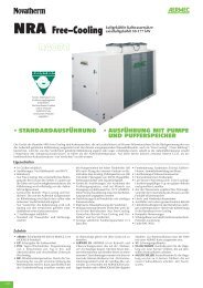
GRANDEZZE DISPONIBILI<br />
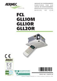
I ventil<strong>con</strong>vettori della serie FCXI_AS sono disponibili in:<br />
5 grandezze<br />
<strong>con</strong> batteria a 3 ranghi<br />
FCXI 20 AS<br />
FCXI 30 AS<br />
FCXI 40 AS<br />
FCXI 50 AS<br />
FCXI 80 AS<br />
FCXI_AS: senza pannello comandi e <strong>con</strong> motore Inverter,<br />
scambiatore 3 ranghi, mobile alto per installazione verticale<br />
verniciato <strong>con</strong> polvere poliestere anticorrosione, colore RAL<br />
9002. La griglia di mandata e gli zoccoli per il montaggio a<br />
pavimento (accessorio ZX) sono in materiale plastico di colore<br />
RAL 7044. Necessita di pannello comandi esterno (accessorio).<br />
DATI TECNICI E LIMITI DI FUNZIONAMENTO<br />
Massima temperatura ingresso acqua<br />
Massima pressione d’esercizio<br />
Limiti di temperatura ambiente Ta<br />
Limiti di umidità relativa nell'ambiente U.R.<br />
Portata minima<br />
Portata massima<br />
Alimentazione elettrica<br />
Le prestazioni sono riferite alle seguenti<br />
<strong>con</strong>dizioni:<br />
- alla massima velocità motore;<br />
Temperatura dell’acqua<br />
Al fine di evitare stratificazioni di aria<br />
nell’ambiente, ed avere quindi una<br />
migliore miscelazione, si <strong>con</strong>siglia di non<br />
alimentare il <strong>ventil<strong>con</strong>vettore</strong> <strong>con</strong> acqua<br />
Minima temperatura media dell’acqua<br />
Se il <strong>ventil<strong>con</strong>vettore</strong> funziona in<br />
modo <strong>con</strong>tinuativo in raffreddamento<br />
all’interno di un ambiente <strong>con</strong> elevata<br />
umidità relativa, si potrebbe avere<br />
formazione di <strong>con</strong>densa sulla mandata<br />
dell’aria e all’esterno dell’apparecchio.<br />
Tale <strong>con</strong>densa, potrebbe depositarsi<br />
sul pavimento e sugli eventuali oggetti<br />
sottostanti.<br />
MINIMA TEMPERATURA MEDIA ACQUA<br />
20 30 40 50 80<br />
80°C<br />
8 bar<br />
0°C < Ta < 40°C<br />
U.R. < 85%<br />
[l/h] 100 100 150 150 300<br />
[l/h] 750 750 1100 1150 2200<br />
230V ( ±10% ) ~ 50Hz<br />
- la potenza assorbita totale è data dalla<br />
somma della potenza assarbita dall'unità<br />
<strong>con</strong> la potenza assorbita dagli acces-<br />
più calda di 65°C.<br />
L’uso di acqua <strong>con</strong> temperature elevate<br />
potrebbe provocare scricchiolii dovuti<br />
alle diverse dilatazioni termiche degli<br />
elementi (plastici e metallici), ciò<br />
Per evitare fenomeni di <strong>con</strong>densazione<br />
sulla struttura esterna dell’apparecchio<br />
<strong>con</strong> ventilatore in funzione, la temperatura<br />
media dell’acqua non deve essere<br />
inferiore ai limiti riportati nella tabella<br />
sottostante, che dipendono dalle <strong>con</strong>dizioni<br />
termo-igrometriche dell’aria<br />
ambiente.<br />
I suddetti limiti si riferis<strong>con</strong>o al funzionamento<br />
<strong>con</strong> ventilatore in moto<br />
I ventil<strong>con</strong>vettori della serie FCXI_U sono disponibili in:<br />
5 grandezze<br />
<strong>con</strong> batteria a 3 ranghi<br />
FCXI 20 U<br />
FCXI 30 U<br />
FCXI 40 U<br />
FCXI 50 U<br />
FCXI 80 U<br />
FCXI_U: senza pannello comandi e <strong>con</strong> motore Inverter, scambiatore<br />
3 ranghi, mobile universale per installazione verticale<br />
a pavimento oppure pensile, verniciato <strong>con</strong> polvere poliestere<br />
anticorrosione, colore RAL 9002. Le griglie di mandata e di<br />
aspirazione sono in materiale plastico di colore RAL 7044. Necessita<br />
di pannello comandi esterno (accessorio).<br />
FCXI 20U ÷ 54U<br />
sori collegati e dichiarata nei relativi<br />
manuali.<br />
comunque non provoca danni all’unità<br />
se non si supera la massima temperatura<br />
di esercizio.<br />
alla minima velocità.<br />
In caso di prolungata situazione <strong>con</strong><br />
ventilatore spento e passaggio di acqua<br />
fredda in batteria, è possibile la formazione<br />
di <strong>con</strong>densa all’esterno dell’apparecchio,<br />
pertanto si <strong>con</strong>siglia l’inserimento<br />
dell’accessorio valvola a tre<br />
vie .<br />
Temperatura a bulbo secco dell’aria ambiente °C<br />
21 23 25 27 29 31<br />
15 3 3 3 3 3 3<br />
Temperatura a bulbo umido 17 3 3 3 3 3 3<br />
dell’aria ambiente °C 19 3 3 3 3 3 3<br />
21 6 5 4 3 3 3<br />
23 - 8 7 6 5 5<br />
IFCXIUASLJ 1003 - 5383600_01<br />
FCXI 80U ÷ 84U<br />
9<br />
Italiano
Italiano<br />
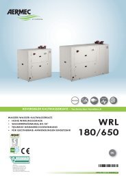
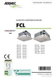
COMPONENTI PRINCIPALI<br />
1 Dispositivo Inverter<br />
2 Batteria di scambio termico<br />
3 Filtro dell'aria (aspirazione)<br />
4 Mobile di copertura (RAL9002)<br />
5 Motore elettrico<br />
FCXI 40 U<br />
DESCRIZIONE<br />
Tipologie d’impianto<br />
I ventil<strong>con</strong>vettori sono progettati per<br />
impianti a 2 e 4 tubi, nelle varianti:<br />
- 3R : senza valvola;<br />
- 3R : <strong>con</strong> valvola acqua (VCF);<br />
- 3R : <strong>con</strong> batteria 1R ad acqua calda<br />
(BV) e 2 valvole (VCF).<br />
Ventilazione<br />
La ventilazione a velocità variabile può<br />
essere comandata sia manualmente<br />
che automaticamente dal pannello<br />
comandi.<br />
BATTERIA DI SCAMBIO TERMICO<br />
Batteria <strong>con</strong> tu bo di rame e alettatura in<br />
alluminio bloccata mediante espansione<br />
meccanica dei tubi. I collettori so no<br />
corredati di attacchi femmina e sfiati<br />
aria nella parte alta della batteria.<br />
SEZIONE FILTRANTE<br />
Filtro <strong>con</strong> classe di filtrazione G2, autoestinguenza<br />
B1 (DIN 4102).<br />
Facilmente estraibile e costruito <strong>con</strong><br />
materiali rigenerabili, può essere pulito<br />
mediante lavaggio.<br />
GRUPPO ELETTROVENTILANTE<br />
È costituito da ventilatori centrifughi a<br />
doppia aspirazione <strong>con</strong> pale sviluppate<br />
in lunghezza per ottenere elevata portata<br />
<strong>con</strong> basso numero di giri. I ventilatori<br />
sono direttamente accoppiati all'al-<br />
10<br />
IFCXIUASLJ 1003 - 5383600_01<br />
bero del motore elettrico "brushless" .<br />
Il motore elettrico "brushless" è ammortizzato<br />
<strong>con</strong> supporti elastici.<br />
Il motore elettrico "brushless" nasce dalla<br />
fusione delle più sofisticate tecnologie<br />
nel campo della meccanica e dell'elettronica.<br />
Il motore elettrico "brushless" è un motore<br />
senza <strong>con</strong>tatti striscianti tra rotore<br />
e statore. Tramite un dispositivo <strong>inverter</strong><br />
dedicato è possibile <strong>con</strong>trollare la<br />
velocità e la coppia del rotore in modo<br />
<strong>con</strong>tinuo, semplicemente agendo sulle<br />
correnti di statore.<br />
Rispetto ai tradizionali motori a corrente<br />
alternata, il motore elettrico "brushless"<br />
presenta enormi vantaggi:<br />
- Ridotta usura<br />
- Possibilità di regolare la velocità di<br />
rotazione in modo preciso e <strong>con</strong>tinuo<br />
(0-100%)<br />
- Maggiore rendimento energetico<br />
- Maggiore durata ed affidabilità<br />
STRUTTURA PORTANTE<br />
È realizzata in lamiera zincata di adeguato<br />
spessore. Nella parte posteriore<br />
ha i fori per il fissaggio a muro dell'apparecchio.<br />
Il gruppo ventilante è chiuso<br />
anteriormente da un pannello metallico.<br />
Ogni apparecchio è corredato di<br />
bacinelle raccolta <strong>con</strong>densa sia per<br />
6 Ventilatore<br />
7 Struttura portante<br />
8 Scarico <strong>con</strong>densa<br />
9 Collegamenti idraulici<br />
10 Testata <strong>con</strong> alette orientabili (RAL7044)<br />
l'installazione verticale che per l'installazione<br />
orizzontale.<br />
SCARICO CONDENSA<br />
Ogni apparecchio è corredato di bacinelle<br />
raccolta <strong>con</strong>densa <strong>con</strong> collegamento<br />
per la fuori uscita della <strong>con</strong>densa<br />
prodotta dall’unità in raffrescamento.<br />
COLLEGAMENTI IDRAULICI<br />
I collegamenti, posizionati nella fiancata<br />
sinistra, sono ad attacco femmina.<br />
È prevista la possibilità di ruotare la<br />
batteria.<br />
MO BI LE DI CO PER TU RA<br />
Involucro colore RAL9002<br />
Griglie colore RAL7044<br />
L’involucro è realizzato in lamiera di<br />
acciaio zincato e verniciato <strong>con</strong> polveri<br />
poliestere per garantire alta resistenza<br />
alla ruggine e alla corrosione.<br />
Gli zoccoli (accessorio per FCXI_AS)<br />
sono in materiale plastico di colore<br />
RAL7044.<br />
PANNELLO COMANDI<br />
Utilizzare un pannello comandi <strong>con</strong> termostato<br />
e <strong>con</strong>trollo delle velocità di<br />
ventilazione <strong>con</strong> uscite 0-10V .
INSTALLAZIONE<br />
ATTENZIONE: prima di effettuare qualsiasi<br />
intervento, assicurarsi che l’alimentazione<br />
elettrica sia disinserita.<br />
ATTENZIONE: L'apparecchio deve essere<br />
installato <strong>con</strong>formemente alle regole<br />
impiantistiche nazionali.<br />
ATTENZIONE: i collegamenti elettrici,<br />
l’installazione dei ventil<strong>con</strong>vettori e<br />
dei loro accessori devono essere eseguiti<br />
solo da soggetti in possesso dei<br />
requisiti tecnico-professionali di abilitazione<br />
all’installazione, alla trasformazione,<br />
all’ampliamento e alla manutenzione<br />
degli impianti ed in grado di<br />
INSTALLAZIONE DELL'UNITA<br />
Per installare l’unità procedere come<br />
segue:<br />
- Estrarre il filtro dell’aria.<br />
- Togliere il mobile di copertura.<br />
- Nella installazione a parete, si mantenga<br />
una distanza minima dal pavimento<br />
di 80 mm. In caso di installazione a<br />
pavimento per mezzo degli zoccoli, si<br />
faccia riferimento alle istruzioni a corredo<br />
dell’accessorio.<br />
- Per il fissaggio al muro usare dei tasselli<br />
ad espansione (non forniti).<br />
Nel caso si utilizzi l’accessorio Supporto<br />
(accessorio AMP), procedere come<br />
segue:<br />
Montare i 4 supporti ai lati dell’apparecchio<br />
inserendo nell’apposita feritoia<br />
la linguetta superiore e fissando la<br />
parte inferiore al frutto per mezzo delle<br />
viti a corredo.<br />
Fissare a soffitto le flange mediante<br />
tasselli ad espansione (non forniti); per<br />
le posizioni relative tra flange e frutto<br />
<strong>con</strong>sultare i dati dimensionali.<br />
- Applicare gli eventuali accessori.<br />
La valvola VCF e la bacinella BC4 non<br />
possono essere installate <strong>con</strong>temporaneamente<br />
sullo stesso <strong>ventil<strong>con</strong>vettore</strong>.<br />
COLLEGAMENTI IDRAULICI<br />
- Effettuare i collegamenti idraulici.<br />
- In caso di smontaggio e nuova installazione,<br />
utilizzare guarnizioni nuove.<br />
La posizione, il tipo e il diametro degli<br />
attacchi idraulici sono riportati nei dati<br />
dimensionali.<br />
Si <strong>con</strong>siglia di isolare adeguatamente<br />
le tubazioni dell’acqua e/o di installare<br />
l’apposita bacinella ausiliaria di<br />
raccolta <strong>con</strong>densa, disponibile come<br />
167 mm<br />
verificare gli stessi ai fini della sicurezza<br />
e della funzionalità.<br />
ATTENZIONE: Installare un dispositivo,<br />
interruttore generale o spina elettrica<br />
che <strong>con</strong>senta di interrompere completamente<br />
l'alimentazione elettrica<br />
dall'apparecchio.<br />
Vengono qui riportate le indicazioni<br />
essenziali per una corretta installazione<br />
delle apparecchiature.<br />
Si lascia comunque all'esperienza<br />
dell'installatore il perfezionamento<br />
di tutte le operazioni a se<strong>con</strong>da delle<br />
esigenze specifiche.<br />
Eseguire i collegamenti idraulici come<br />
indicato nel capitolo dedicato.<br />
Eseguire il collegamento dello scarico<br />
della <strong>con</strong>densa come indicato nel capitolo<br />
dedicato. I ventil<strong>con</strong>vettori che<br />
funzioneranno solamente in riscaldamento<br />
non richiedono lo scarico della<br />
<strong>con</strong>densa.<br />
Eseguire i collegamenti elettrici come<br />
indicato nel capitolo dedicato e quanto<br />
riportato negli schemi elettrici.<br />
Eseguire l'installazione ed i collegamenti<br />
degli eventuali accessori.<br />
Concludere l'installazione rimontando<br />
l'involucro e il filtro dell'aria.<br />
Avviare il <strong>ventil<strong>con</strong>vettore</strong> e verificare<br />
il funzionamento dei componenti e di<br />
tutte le funzioni.<br />
ZX<br />
49 mm<br />
65 mm<br />
FCXI_AS<br />
accessorio, per evitare gocciolamenti<br />
durante il funzionamento in raffreddamento.<br />
Dopo l'installazione verificare la tenuta<br />
dei collegamenti.<br />
Il <strong>ventil<strong>con</strong>vettore</strong> deve essere installato<br />
in posizione tale che l’aria possa essere<br />
distribuita in tutta la stanza, che non<br />
vi siano ostacoli (tende o oggetti) al<br />
passaggio dell’aria dalle griglie di<br />
aspirazione.<br />
Il <strong>ventil<strong>con</strong>vettore</strong> deve essere installato<br />
in posizione tale da <strong>con</strong>sentire facilmente<br />
la manutenzione ordinaria (pulizia<br />
del filtro) e straordinaria, oltre che<br />
l’accesso alla valvola di sfiato dell’aria<br />
sulla fiancata del telaio (lato attacchi).<br />
IFCXIUASLJ 1003 - 5383600_01<br />
1<br />
B<br />
A<br />
2<br />
B<br />
A<br />
FCXI_U<br />
AMP<br />
FCXI_U<br />
B<br />
A<br />
11<br />
Italiano
Italiano<br />
SCARICO CONDENSA<br />
In caso di installazione orizzontale,<br />
montare il raccordo di scarico della<br />
<strong>con</strong>densa fornito a corredo. Si abbia<br />
cura di sigillare <strong>con</strong> sili<strong>con</strong>e la <strong>con</strong>nessione<br />
tra bacinella e raccordo. La<br />
rete di scarico della <strong>con</strong>densa deve<br />
essere opportunamente dimensionata<br />
e le tubazioni posizionate in modo da<br />
mantenere lungo il percorso un’ade-<br />
COLLEGAMENTI ELETTRICI<br />
ATTENZIONE: prima di effettuare qualsiasi<br />
intervento, assicurarsi che l’alimentazione<br />
elettrica sia disinserita.<br />
L’unità deve essere collegata<br />
direttamente ad un attacco elettrico o<br />
ad un circuito indipendente.<br />
Installare un dispositivo, interruttore<br />
generale o spina elettrica che <strong>con</strong>senta<br />
di interrompere completamente<br />
l'alimentazione elettrica dall'apparecchio.<br />
Per proteggere l’unità <strong>con</strong>tro i cortocircuiti,<br />
montare sulla linea di alimentazione<br />
un interruttore onnipolare<br />
magnetotermico 2A 250V (IG) <strong>con</strong><br />
distanza minima di apertura dei <strong>con</strong>tatti<br />
di 3mm.<br />
CARATTERISTICHE DEI CAVI DI<br />
COLLEGAMENTO<br />
Usare cavi tipo H05V-K oppure N07V-K<br />
<strong>con</strong> isolamento 300/500 V incassati in<br />
ROTAZIONE DELLA BATTERIA<br />
Se per motivi di allacciamenti idraulici,<br />
si dovesse ruotare la batteria, dopo aver<br />
tolto il pannello di chiusura anteriore,<br />
procedere come segue:<br />
– Togliere la bacinella di raccolta<br />
<strong>con</strong>densa.<br />
– Togliere il coperchio di chiusura della<br />
batteria svitando le viti.<br />
– Togliere le viti che fissano la batteria e<br />
quindi estrarla.<br />
– Rimuovere i semitranciati dalla fiancata<br />
destra.<br />
– Ruotare la batteria e fissarla <strong>con</strong> le viti<br />
12<br />
IFCXIUASLJ 1003 - 5383600_01<br />
guata pendenza (min.1%). Nel caso<br />
di scarico nella rete fognaria, si <strong>con</strong>siglia<br />
di realizzare un sifone che impedisca<br />
la risalita di cattivi odori verso gli<br />
ambienti.<br />
Eseguire una prova del funzionamento e<br />
tenuta dell'impianto di scarico <strong>con</strong>densa<br />
versando dell'acqua nella bacinella.<br />
tubo o canalina.<br />
Tutti i cavi devono essere incassati<br />
in tubo o canalina finchè non sono<br />
all’interno del <strong>ventil<strong>con</strong>vettore</strong>.<br />
I cavi all’uscita dal tubo o canalina<br />
devono essere posizionati in modo da<br />
non subire sollecitazioni a trazione o<br />
torsione e comunque protetti da agenti<br />
esterni.<br />
Cavi a trefolo possono essere usati solo<br />
<strong>con</strong> capicorda. Assicurarsi che i trefoli<br />
dei fili siano ben inseriti.<br />
Gli schemi elettrici sono soggetti ad un<br />
<strong>con</strong>tinuo aggiornamento, è obbligatorio<br />
quindi fare riferimento a quelli a<br />
bordo macchina.<br />
Il pannello comandi non può essere<br />
montato su una parete metallica, salvo<br />
che questa sia collegata alla presa di<br />
terra in modo permanente.<br />
Nell’abbinamento dei pannelli coman-<br />
precedentemente tolte.<br />
– Rimontare il coperchio di chiusura,<br />
fissandolo <strong>con</strong> le viti.<br />
- Rimontare i tappi in plastica, forniti<br />
a corredo, nei fori lasciati liberi dagli<br />
attacchi idraulici.<br />
- Tutte le bacinelle sono predisposte per<br />
lo scarico della <strong>con</strong>densa su entrambi<br />
i lati. In caso di installazione verticale,<br />
qualora si voglia effettuare lo scarico<br />
della <strong>con</strong>densa sul lato destro, é<br />
necessario spostare a destra il raccordo<br />
di scarico.<br />
7<br />
11<br />
10<br />
di a distanza deve essere rispettato<br />
lo schema elettrico relativo. Prima di<br />
installare il pannello comandi leggere<br />
attentamente le istruzioni, se necessario<br />
procedere alla <strong>con</strong>figurazione del<br />
pannello.<br />
Nel caso sia installata la valvola a<br />
tre vie, la sonda di minima temperatura<br />
dell’acqua dev’essere spostata<br />
dalla sua sede nella batteria, al tubo<br />
di mandata a monte della valvola.<br />
Collegare la valvola e la sonda alla<br />
morsettiera nelle posizioni indicate<br />
nello schema elettrico.<br />
ATTENZIONE: verificare se l’installazione<br />
é stata eseguita in modo corretto.<br />
Seguire le procedure di verifica<br />
indicate nei manuali dei pannelli<br />
comandi.<br />
– Sfilare i collegamenti elettrici<br />
dalla fiancata destra, rimuovere il<br />
semitranciato e spostare il passacavo<br />
da destra a sinistra.<br />
– Spostare i collegamenti elettrici sul lato<br />
sinistro facendoli passare attraverso il<br />
passacavo.<br />
– Spostare la morsettiera, il cavallotto<br />
della messa a terra e gli eventuali<br />
dispositivi elettrici sul lato sinistro sul<br />
lato sinistro.<br />
4<br />
9<br />
Ø est. 20,5mm<br />
5<br />
8<br />
6<br />
3
Congratulations on your purchase of this Aermec FCXI <strong>fan</strong> <strong>coil</strong>.<br />
Made <strong>with</strong> materials of superior quality in strict compliance <strong>with</strong> safety regulations, "FCXI" is<br />
easy to use and will have a long life.<br />
Thanks to Aermec's FCXI range of <strong>inverter</strong> <strong>fan</strong> <strong>coil</strong>s, brushless technology can now make<br />
inroads in the field of chilled water air <strong>con</strong>ditioning, bringing notable energy savings along<br />
<strong>with</strong> the precise <strong>con</strong>trol of both air temperature and humidity in the air-<strong>con</strong>ditioned rooms.<br />
TABLE OF CONTENTS<br />
Important information Maintenance Packaging Use<br />
Description Versions Operating limits<br />
Main components Description of components<br />
Installation information Installing the unit Water <strong>con</strong>nections<br />
Condensate discharge <strong>con</strong>nections<br />
Electrical wirings<br />
Rotating the <strong>coil</strong><br />
Dimensions<br />
Wiring diagrams<br />
TROUBLESHOOTING<br />
IFCXIUASLJ 1003 - 5383600_01<br />
14<br />
15<br />
16<br />
17<br />
18<br />
18<br />
37<br />
40<br />
41<br />
13<br />
English
English<br />
IMPORTANT INFORMATION AND MAINTENANCE<br />
WARNING: the <strong>fan</strong> <strong>coil</strong> is <strong>con</strong>nected<br />
to the power supply and a water circuit.<br />
Any operation by persons who<br />
do not possess the required technical<br />
skills can lead to personal injury to the<br />
operator or damage to the unit and<br />
surrounding objects.<br />
POWER THE FAN COIL ONLY WITH<br />
230V, SINGLE-PHASE VOLTAGE<br />
Any other type of power supply could<br />
permanently damage the <strong>fan</strong> <strong>coil</strong>.<br />
DO NOT USE THE FAN COIL IMPROPERLY<br />
Do not use the <strong>fan</strong> <strong>coil</strong> for animal husbandry<br />
applications (e.g. incubation).<br />
AIR THE ROOM<br />
Periodically air the room in which the<br />
<strong>fan</strong> <strong>coil</strong> has been installed. This is particularly<br />
important if the room is occupied<br />
by many people, or if gas appliances<br />
or sources of odours are present.<br />
ADJUST TEMPERATURE ADEQUATELY<br />
The room temperature should be adjusted<br />
in order to provide maximum comfort<br />
to the people in the room, especially<br />
if they are elderly, children or<br />
sick people; avoid differences over 7°C<br />
between the outdoor temperature and<br />
the temperature inside the room in<br />
summer.<br />
In summer, a temperature that is too low<br />
causes higher electrical <strong>con</strong>sumption.<br />
PACKAGING<br />
The <strong>fan</strong> <strong>coil</strong>s are shipped in standard package which <strong>con</strong>sists of expanded polystyrene foam and cardboard shells.<br />
USE<br />
Consult <strong>con</strong>trol panel manual for installation and use instructions.<br />
14<br />
IFCXIUASLJ 1003 - 5383600_01<br />
CORRECT AIR JET AIMING ADJUSTMENT<br />
Air coming out from the <strong>fan</strong> <strong>coil</strong> must<br />
not reach people directly; in fact, even<br />
if the air is warmer than the room temperature,<br />
it could cause a cold sensation<br />
and result in discomfort.<br />
DO NOT USE EXCESSIVELY HOT WATER<br />
Clean the <strong>fan</strong> <strong>coil</strong> <strong>with</strong> a soft cloth or<br />
sponge soaked in water not over 40°C.<br />
Do not use chemical products or solvents<br />
to clean any part of the <strong>fan</strong> <strong>coil</strong>.<br />
Do not spray water on the outer or<br />
inner surfaces of the <strong>fan</strong> <strong>coil</strong> (it might<br />
cause short circuits).<br />
CLEAN THE FILTER FREQUENTLY<br />
Cleaning the filter frequently guarantees<br />
enhanced operating efficiency.<br />
Check whether the filter is very dirty: if it<br />
is, clean it more often.<br />
Clean frequently; remove the accumulated<br />
dust <strong>with</strong> a vacuum cleaner.<br />
Once the filter is clean, refit it to the <strong>fan</strong><br />
<strong>coil</strong> following the removal instructions<br />
but in reverse order.<br />
SUPPLEMENTARY CLEANING<br />
The fact that the blades of examinable<br />
shrouds can be removed (operation<br />
done only by adequately skilled technicians)<br />
ensures a thorough cleaning of<br />
the internal components, which is particularly<br />
important when installing the<br />
unit in crowded areas or venues requiring<br />
high hygiene standards.<br />
DURING OPERATION<br />
Always leave the filter fitted on the <strong>fan</strong><br />
<strong>coil</strong> during operation (otherwise dust in<br />
the air could soil the <strong>coil</strong> surface area).<br />
WHAT IS NORMAL<br />
In cooling mode, water vapour may be<br />
present in the air delivery of the <strong>fan</strong><br />
<strong>coil</strong>.<br />
In the heating mode, a slight hiss<br />
might be heard close to the <strong>fan</strong> <strong>coil</strong>.<br />
Sometimes the <strong>fan</strong> <strong>coil</strong> might give off<br />
unpleasant smells due to the accumulation<br />
of substances present in the air of<br />
the room (clean the filter more often,<br />
especially if the room is not ventilated<br />
regularly).<br />
While the unit is functioning, there<br />
could be noises and creaks inside<br />
the device due to the various thermal<br />
expansions of the elements (plastic and<br />
metal), but this does not indicate any<br />
malfunction and does not damage the<br />
unit unless the maximum input water<br />
temperature is exceeded.
DESCRIPTION OF THE UNIT<br />
MACHINE PURPOSE<br />
The <strong>fan</strong> <strong>coil</strong> is a room air treatment terminal unit for both winter and summer operation.<br />
AVAILABLE SIZES<br />
The FCXI_AS <strong>fan</strong> <strong>coil</strong>s are available in:<br />
5 sizes<br />
<strong>with</strong> 3-row <strong>coil</strong><br />
FCXI 20 AS<br />
FCXI 30 AS<br />
FCXI 40 AS<br />
FCXI 50 AS<br />
FCXI 80 AS<br />
FCXI_AS: <strong>with</strong>out <strong>con</strong>trol panel and <strong>with</strong> Inverter motor, 3-row<br />
heat exchanger, high cabinet for vertical installation, varnished<br />
<strong>with</strong> anti-corrosion polyester powder (colour RAL 9002). The<br />
delivery grille and the feet for floor-standing solutions (ZX accessory)<br />
are made of plastic of the colour RAL 7044. Requires<br />
external <strong>con</strong>trol panel (accessory).<br />
TECHNICAL DATA AND OPERATING LIMITS<br />
Maximum water inlet temperature<br />
Maximum operating pressure<br />
Room temperature limits Ta<br />
Relative humidity limits in the room R.H.<br />
Minimum flow rate<br />
Maximum flow rate<br />
Power supply<br />
Performance values refer to the following<br />
<strong>con</strong>ditions:<br />
- at the maximum motor speed;<br />
Water temperature<br />
In order to prevent air stratification in the<br />
room, and therefore to achieve improved<br />
mixing, it is advisable not to supply the <strong>fan</strong><br />
<strong>coil</strong> <strong>with</strong> water at a temperature over 65°C.<br />
Minimum average water temperature<br />
If the <strong>fan</strong> <strong>coil</strong> is working in <strong>con</strong>tinuous<br />
cooling mode in an environment<br />
where the relative humidity is high,<br />
<strong>con</strong>densate might form on the air<br />
delivery and on the outside of the<br />
device. This <strong>con</strong>densate might be<br />
deposited on any objects underneath<br />
and on the floor.<br />
MINIMUM AVERAGE WATER TEMPERATURE<br />
The FCXI_U <strong>fan</strong> <strong>coil</strong>s are available in:<br />
5 sizes<br />
<strong>with</strong> 3-row <strong>coil</strong><br />
FCXI 20 U<br />
FCXI 30 U<br />
FCXI 40 U<br />
FCXI 50 U<br />
FCXI 80 U<br />
20 30 40 50 80<br />
80°C<br />
8 bar<br />
0°C < Ta < 40°C<br />
R.H. < 85%<br />
[l/h] 100 100 150 150 300<br />
[l/h] 750 750 1100 1150 2200<br />
230 V ( ±10% ) ~ 50 Hz<br />
- the total input power is determined by<br />
adding the input power for the unit to<br />
the input power for the accessories <strong>con</strong>-<br />
The use of water at high temperatures<br />
could cause squeaking due to the<br />
different thermal expansions of the<br />
elements (plastic and metal), this<br />
does not however cause damage to<br />
To avoid <strong>con</strong>densate on the external<br />
structure of the device while the <strong>fan</strong> is<br />
functioning, the average temperature<br />
of the water must not be lower than<br />
the limits shown in the table below,<br />
that depend on the thermo-hygrometric<br />
<strong>con</strong>ditions of the air in the room.<br />
The limits mentioned above refer to<br />
operation while the <strong>fan</strong> is set<br />
to its minimum speed level.<br />
FCXI_U: <strong>with</strong>out <strong>con</strong>trol panel and <strong>with</strong> Inverter motor, 3-row<br />
heat exchanger, universal cabinet for vertical fl oor-standing in-<br />
stallation or wall-mounting, varnished <strong>with</strong> anti-corrosion pol-<br />
yester powder, colour RAL 9002. The air delivery and suction<br />
grilles are made using plastic material in colour RAL 7044.<br />
Requires external <strong>con</strong>trol panel (accessory).<br />
FCXI 20U ÷ 54U<br />
nected and declared in the corresponding<br />
manuals.<br />
the unit if the maximum operating<br />
temperature is not exceeded.<br />
In the event of prolonged <strong>fan</strong> inactivity<br />
and <strong>with</strong> cold water passing through<br />
the <strong>coil</strong>, <strong>con</strong>densate may form on the<br />
external case of the unit. As a result,<br />
we recommend including the 3-way<br />
valve accessory.<br />
Temperature of the air in the room <strong>with</strong> dry bulb °C<br />
21 23 25 27 29 31<br />
15 3 3 3 3 3 3<br />
Temperature of the air in the room 17 3 3 3 3 3 3<br />
<strong>with</strong> wet bulb °C 19 3 3 3 3 3 3<br />
21 6 5 4 3 3 3<br />
23 - 8 7 6 5 5<br />
IFCXIUASLJ 1003 - 5383600_01<br />
FCXI 80U ÷ 84U<br />
15<br />
English
English<br />
MAIN COMPONENTS<br />
1 Inverter device<br />
2 Heat exchange <strong>coil</strong><br />
3 Air filter (suction)<br />
4 Protective cabinet (RAL9002)<br />
5 Electric motor<br />
FCXI 40 U<br />
DESCRIPTION<br />
System types<br />
The <strong>fan</strong> <strong>coil</strong>s are designed for systems<br />
<strong>with</strong> 2 and 4 pipes, in the versions:<br />
- 3R: <strong>with</strong>out valve;<br />
- 3R: <strong>with</strong> water valve (VCF);<br />
- 3R: <strong>with</strong> 1-row hot water <strong>coil</strong> (BV) and<br />
2 valves (VCF).<br />
Ventilation<br />
Variable speed ventilation can be commanded<br />
either manually or automatically<br />
from the <strong>con</strong>trol panel.<br />
HEAT EXCHANGE COIL<br />
Coil <strong>with</strong> copper pipe and aluminium fins<br />
blocked by means of the mechanical<br />
expansion of the pipes. The collectors<br />
are fitted <strong>with</strong> female <strong>con</strong>nections and<br />
air vents in the upper part of the <strong>coil</strong>.<br />
FILTERING SECTION<br />
Filter in filtering class G2, self-extinguishing<br />
B1 (DIN 4102).<br />
Easily removable and made from regenerable<br />
materials. May be cleaned by<br />
washing.<br />
ELECTRIC FAN UNIT<br />
This <strong>con</strong>sists of double suction centrifugal<br />
<strong>fan</strong>s <strong>with</strong> lengthways blades<br />
to obtain a high air flow <strong>with</strong> a low<br />
number of revs. The <strong>fan</strong>s are directly<br />
coupled <strong>with</strong> the shaft of the "brushless"<br />
electric motor.<br />
16<br />
IFCXIUASLJ 1003 - 5383600_01<br />
The "brushless" electric motor is cushioned<br />
<strong>with</strong> elastic supports.<br />
The "brushless" electric motor is the<br />
result of combining the most sophisticated<br />
technologies from the fields of<br />
mechanics and electronics.<br />
The "brushless" electric motor has no<br />
sliding <strong>con</strong>tacts between the rotor and<br />
the stator. With the special <strong>inverter</strong><br />
device, it is possible to <strong>con</strong>trol the<br />
speed and torque of the rotor <strong>con</strong>tinuously,<br />
just by means of the stator currents.<br />
Compared <strong>with</strong> the traditional alternate<br />
current motors, the "brushless" electric<br />
motor offers huge advantages:<br />
- Reduced wear and tear<br />
- The possibility to regulate the rotation<br />
speed in a precise, <strong>con</strong>tinuous manner<br />
(0-100%)<br />
- Higher energy yields<br />
- Longer life and greater reliability<br />
LOAD-BEARING STRUCTURE<br />
Made of galvanised sheet iron of a suitable<br />
thickness. There are holes on the<br />
back for fixing the device to the wall.<br />
The <strong>fan</strong> unit is closed at the front <strong>with</strong><br />
a metal panel. Every device is equipped<br />
<strong>with</strong> <strong>con</strong>densate collection trays (for<br />
both vertical and horizontal installation).<br />
6 Fan<br />
7 Load-bearing structure<br />
8 Condensate drain<br />
9 Plumbing <strong>con</strong>nections<br />
10 Head <strong>with</strong> adjustable fins (RAL7044)<br />
CONDENSATE DRAIN<br />
Every device is equipped <strong>with</strong> <strong>con</strong>densate<br />
collection trays, <strong>with</strong> a <strong>con</strong>nection<br />
for draining the <strong>con</strong>densate produced<br />
by the unit in cooling mode.<br />
WATER CONNECTIONS<br />
The <strong>con</strong>nections, located on the left<br />
hand side, are female. The <strong>coil</strong> may<br />
also be rotated.<br />
CABINET<br />
Casing in RAL9002<br />
Grey colour RAL7044<br />
The casing is made of galvanised steel,<br />
varnished <strong>with</strong> polyester powders to<br />
guarantee high resistance to rust and<br />
corrosion.<br />
The feet (accessory for FCXI_AS) are in<br />
plastic, colour RAL7044.<br />
CONTROL PANEL<br />
Use a <strong>con</strong>trol panel <strong>with</strong> thermostat and<br />
ventilation speed <strong>con</strong>trol, <strong>with</strong> 0-10V<br />
outputs.
INSTALLATION<br />
WARNING: check that the power supply<br />
is dis<strong>con</strong>nected before carrying out<br />
any procedures on the unit.<br />
WARNING: the appliance must be fitted<br />
according to the national regulations<br />
on process plant engineering.<br />
WARNING: electrical wirings, installation<br />
of the <strong>fan</strong> <strong>coil</strong>s and relevant accessories<br />
should be performed by a technician<br />
who has the necessary technical and<br />
professional expertise to install, modify,<br />
extend and maintain systems, and who<br />
is able to check the systems for the purposes<br />
of safety and correct operation.<br />
INSTALLING THE UNIT<br />
To install the unit, proceed as follows:<br />
- Remove the air filter<br />
- Remove the covering cabinet<br />
- With wall-mounted units, keep a minimum<br />
clearance of 80mm from the<br />
floor. With floor-standing units on feet,<br />
refer to the instructions supplied <strong>with</strong><br />
the accessory<br />
- Use wall plugs (not supplied) for wallmounted<br />
installations<br />
When using the support accessory (AMP<br />
accessory), proceed as follows:<br />
Assemble the 4 supports at the sides of<br />
the device, inserting the upper tang in the<br />
hole and fixing the lower part to the component<br />
by means of the screws supplied.<br />
Fix the flanges to the ceiling, using wall<br />
plugs (not supplied); for the relative<br />
positions between the flanges and the<br />
component, refer to the size data<br />
- Apply any accessories.<br />
The VCF valve and the BC4 tray cannot<br />
be installed at the same time on the<br />
same <strong>fan</strong> <strong>coil</strong>.<br />
Make the water <strong>con</strong>nections as<br />
described in the relative chapter.<br />
Make the <strong>con</strong>densate discharge <strong>con</strong>nection<br />
as described in the relative chapter.<br />
WATER CONNECTIONS<br />
- Make the water <strong>con</strong>nections.<br />
- In the event of disassembly and reinstallation,<br />
use new gaskets.<br />
Refer to the size data for the position,<br />
type and diameter of the water <strong>con</strong>nections.<br />
You are advised to adequately insulate<br />
water lines and/or fit the auxiliary<br />
<strong>con</strong>densate drain tray (available as an<br />
accessory), to prevent dripping during<br />
167 mm<br />
WARNING: install a device, main<br />
switch or plug which allows to completely<br />
cut off the power supply from<br />
the unit.<br />
Instructions which are essential for the<br />
proper installation of the equipment are<br />
given here.<br />
The completion of all the operations<br />
in accordance <strong>with</strong> the specific<br />
requirements is however left to the<br />
experience of the installation engineer.<br />
The <strong>fan</strong> <strong>coil</strong> must be installed in such a<br />
position that the air can be distributed<br />
throughout the room and so that there<br />
The <strong>fan</strong> <strong>coil</strong>s that work in heat mode<br />
only do not require <strong>con</strong>densate discharge.<br />
Make the electrical wiring as shown in<br />
the relative chapter and in the wiring<br />
diagrams.<br />
Install and <strong>con</strong>nect any accessories.<br />
Complete the installation by reassembling<br />
the casing and air filter.<br />
Start up the <strong>fan</strong> <strong>coil</strong> and check all the<br />
components and functions are operating<br />
correctly.<br />
ZX<br />
49 mm<br />
65 mm<br />
FCXI_AS<br />
the cooling function.<br />
After installing, check the seal on the<br />
<strong>con</strong>nections.<br />
are no obstacles (curtains or objects) to<br />
the passage of the air from the suction<br />
louvers.<br />
The <strong>fan</strong> <strong>coil</strong> should be installed in such a<br />
way as to facilitate routine (filter cleaning)<br />
and special maintenance operations,<br />
as well as access to the air drain<br />
valve on the side of the unit frame<br />
(<strong>con</strong>nections side).<br />
IFCXIUASLJ 1003 - 5383600_01<br />
1<br />
B<br />
A<br />
2<br />
B<br />
A<br />
FCXI_U<br />
AMP<br />
FCXI_U<br />
B<br />
A<br />
17<br />
English
English<br />
CONDENSATE DRAIN<br />
In the event of horizontal installation,<br />
assemble the <strong>con</strong>densate discharge<br />
<strong>con</strong>nection supplied. Make sure you<br />
seal the <strong>con</strong>nection between the drip<br />
tray and the fitting <strong>with</strong> sili<strong>con</strong>e. The<br />
<strong>con</strong>densate drain network must be<br />
properly scaled and the piping situated<br />
in such a way as to keep an adequate<br />
slope along the route (min. 1%).<br />
ELECTRICAL WIRINGS<br />
WARNING: check that the power supply<br />
is dis<strong>con</strong>nected before carrying<br />
out any procedures on the unit.<br />
The unit must be <strong>con</strong>nected directly<br />
to an electrical outlet or to an<br />
independent circuit.<br />
install a device, main switch or plug<br />
which allows to completely cut off<br />
the power supply from the unit.<br />
To protect the unit against short circuits,<br />
fit an omnipolar thermal-magnetic<br />
trip 2A 250V (IG) to the power<br />
line <strong>with</strong> a minimum <strong>con</strong>tact opening<br />
distance of 3mm.<br />
CHARACTERISTICS OF THE<br />
CONNECTION CABLES<br />
Use H05V-K or N07V-K type cables<br />
<strong>with</strong> 300/500 V <strong>with</strong> insulation, piped<br />
or ducted.<br />
All the cables must be piped or ducted<br />
until they are inside the <strong>fan</strong> <strong>coil</strong>.<br />
ROTATING THE COIL<br />
If the hydraulic <strong>con</strong>nections require the<br />
rotation of the <strong>coil</strong>, remove the front<br />
closure panel and proceed as follows:<br />
- Remove the <strong>con</strong>densate drip tray;<br />
- Undo the screws and remove the <strong>coil</strong><br />
cover;<br />
- Remove the screws securing the <strong>coil</strong>,<br />
then remove the <strong>coil</strong>;<br />
- Remove the push-outs on the righthand<br />
side;<br />
- Rotate the <strong>coil</strong> and secure it <strong>with</strong> the<br />
previously removed screws;<br />
- Reassemble the cover and fix it <strong>with</strong><br />
18<br />
IFCXIUASLJ 1003 - 5383600_01<br />
If <strong>con</strong>densate is discharged into the<br />
sewage system, install a siphon to<br />
prevent the return of unpleasant odours<br />
into the room.<br />
Carry out a functioning and seal test of<br />
the <strong>con</strong>densate drain system by pouring<br />
water into the tray<br />
The cables coming out of the pipe or<br />
duct must not be subject to stretching<br />
or twisting. They must be protected<br />
from external agents.<br />
Stranded cables can only be used <strong>with</strong><br />
crimping terminals. Make sure that the<br />
strands of the wires are inserted properly.<br />
Wiring diagrams are <strong>con</strong>stantly updated.<br />
It is therefore compulsory to refer<br />
to the ones supplied <strong>with</strong> the unit.<br />
The <strong>con</strong>trol panel may not be fitted on<br />
a metal wall unless this is permanently<br />
<strong>con</strong>nected to an earthed outlet.<br />
When using remote <strong>con</strong>trol panels,<br />
the relative wiring diagram must be<br />
respected. Before installing the <strong>con</strong>trol<br />
panel, read the instructions carefully<br />
and <strong>con</strong>figure the panel if necessary.<br />
In installations <strong>with</strong> a three-way valve,<br />
the minimum water temperature sensor<br />
must be relocated from its standard<br />
the screws;<br />
- Reassemble the plastic plugs (supplied)<br />
in the holes left free by the water<br />
<strong>con</strong>nections;<br />
- All the trays can be used to collect<br />
<strong>con</strong>densate on both sides. In case of<br />
vertical installation, to discharge<br />
<strong>con</strong>densate on the right side, position<br />
the drain <strong>con</strong>nection to the right.<br />
- Slide out the electrical wirings from the<br />
right-hand side, remove the push-out<br />
and move the cable grommet from the<br />
right to the left side;<br />
7<br />
11<br />
10<br />
mounting in the <strong>coil</strong> assembly to the<br />
delivery hose upstream of the valve.<br />
Connect the valve and sensor to the<br />
<strong>con</strong>trol board, in the positions indicated<br />
in the wiring diagram.<br />
WARNING: check whether the installation<br />
has been carried out correctly.<br />
Follow the checking procedures indicated<br />
in the <strong>con</strong>trol panel manuals.<br />
- Transfer the electrical wirings to the left<br />
side through the cable grommet;<br />
- Move the <strong>con</strong>trol board, the earthing<br />
u-bolt and any electric devices to the<br />
left-hand side.<br />
4<br />
9<br />
Ø est. 20,5mm<br />
5<br />
8<br />
6<br />
3
Nous désirons vous féliciter pour avoir acheté le <strong>ventilo</strong>-<strong>con</strong>vecteur FCXI Aermec.<br />
Réalisé avec des matériaux de qualité supérieure, dans le plus grand respect des règles de<br />
sécurité, le modèle FCXI est facile à utiliser et a été <strong>con</strong>çu pour durer longtemps.<br />
Grâce à la série de <strong>ventilo</strong>-<strong>con</strong>vecteurs à <strong>inverter</strong> FCXI d'Aermec, la technologie brushless fait<br />
désormais son entrée dans le domaine de la climatisation à eau refroidie, tout en apportant<br />
d'avantages <strong>con</strong>sidérables en termes d'é<strong>con</strong>omie d'énergie et de commande exacte et précise<br />
de la température et de l'humidité relative de l'air des locaux climatisés.<br />
TABLE DES MATIÈRES<br />
Informations importantes Entretien Emballage Emploi<br />
Description Versions Limites de fonctionnement<br />
Composants principaux Description des composants<br />
Informations pour l'installation Installation de l'unité Raccords hydrauliques<br />
Raccords d'évacuation des <strong>con</strong>densats<br />
Raccordements électriques<br />
Rotation de la batterie<br />
Dimensions<br />
Schémas électriques<br />
SOLUTION DES PROBLÈMES<br />
IFCXIUASLJ 1003 - 5383600_01<br />
20<br />
21<br />
22<br />
23<br />
23<br />
25<br />
25<br />
37<br />
40<br />
41<br />
19<br />
Français
Français<br />
INFORMATIONS IMPORTANTES ET ENTRETIEN<br />
ATTENTION : le <strong>ventilo</strong>-<strong>con</strong>vecteur est<br />
raccordé au réseau électrique et au circuit<br />
hydraulique : l’intervention de personnel<br />
sans la compétence technique<br />
spécifique peut blesser l’opérateur ou<br />
endommager l’appareil ou le milieu environnant.<br />
ALIMENTER LE VENTILO-CONVEC-<br />
TEUR EXCLUSIVEMENT AVEC UNE<br />
TENSION DE 230 V, MONOPHASÉE.<br />
L'utilisation d'alimentations électriques<br />
différentes peut endommager le <strong>ventilo</strong>-<strong>con</strong>vecteur<br />
irrémédiablement.<br />
NE PAS UTILISER LE VENTILO-<br />
CONVECTEUR DE MANIÈRE IMPROPRE<br />
Le <strong>ventilo</strong>-<strong>con</strong>vecteur ne doit pas être<br />
utilisé pour l’élevage, la naissance ou<br />
la croissance d’animaux.<br />
VENTILER LA PIÈCE<br />
Il est <strong>con</strong>seillé de ventiler périodiquement<br />
la pièce où le <strong>ventilo</strong>-<strong>con</strong>vecteur est installé,<br />
plus spécialement si plusieurs personnes<br />
l'utilisent ou si des appareils à<br />
gaz ou des sources d’odeurs s'y trouvent.<br />
PROGRAMMER CORRECTEMENT LA<br />
TEMPÉRATURE<br />
La température ambiante doit être réglée<br />
de manière à garantir un maximum<br />
de bien-être aux personnes présentes,<br />
surtout s'il s'agit de personnes âgées,<br />
d'en<strong>fan</strong>ts ou de malades, en évitant des<br />
sauts de température entre l'intérieur et<br />
l'extérieur de plus de 7 °C en été.<br />
En été une température trop basse comporte<br />
une augmentation de la <strong>con</strong>sommation<br />
d'électricité.<br />
EMBALLAGE<br />
Les <strong>ventilo</strong>-<strong>con</strong>vecteurs sont envoyés dans un emballage standard <strong>con</strong>stitué de coques en polystyrène expansé et en carton.<br />
EMPLOI<br />
Consulter le manuel du panneau de commandes pour le mode d'emploi et l'installation.<br />
20<br />
IFCXIUASLJ 1003 - 5383600_01<br />
ORIENTER CORRECTEMENT LE JET D'AIR<br />
L'air qui sort du <strong>ventilo</strong>-<strong>con</strong>vecteur ne<br />
doit pas souffler directement sur les<br />
personnes ; car même s'il est à une<br />
température supérieure à celle de la<br />
pièce, il peut provoquer une sensation<br />
de froid et être gênant.<br />
NE PAS UTILISER DE L'EAU TROP CHAUDE<br />
Pour nettoyer le <strong>ventilo</strong>-<strong>con</strong>vecteur<br />
utiliser des chiffons ou des éponges<br />
souples et mouillés avec de l’eau dont<br />
la température maximale ne dépasse<br />
pas 40 °C. N’utiliser aucun produit<br />
chimique ou solvant pour nettoyer une<br />
partie quel<strong>con</strong>que du <strong>ventilo</strong>-<strong>con</strong>vecteur.<br />
Ne pas vaporiser de l'eau sur les<br />
surfaces externes ou internes du <strong>ventilo</strong>-<strong>con</strong>vecteur<br />
(on risque des courtscircuits).<br />
NETTOYER LE FILTRE PÉRIODIQUEMENT<br />
Un nettoyage fréquent du filtre garantit<br />
une plus grande efficacité de fonctionnement.<br />
Contrôler si le filtre est particulièrement<br />
sale : dans ce cas, répéter l'opération<br />
plus fréquemment.<br />
Nettoyer fréquemment, enlever la poussière<br />
accumulée avec un aspirateur.<br />
Lorsque le filtre est propre, le remonter<br />
sur le <strong>ventilo</strong>-<strong>con</strong>vecteur en effectuant<br />
les opérations en sens inverse au<br />
démontage.<br />
NETTOYAGE EXTRAORDINAIRE<br />
La possibilité d'enlever les vis sans fin<br />
des ventilateurs (à effectuer seulement<br />
par du personnel possédant les com-<br />
pétences spécifiques), permet de réaliser<br />
un nettoyage soigné de l'intérieur,<br />
<strong>con</strong>dition nécessaire pour l'installation<br />
dans des lieux bondés qui demandent<br />
un niveau d'hygiène très élevé.<br />
PENDANT LE FONCTIONNEMENT<br />
Pendant la marche, laisser le filtre toujours<br />
monté sur le <strong>ventilo</strong>-<strong>con</strong>vecteur<br />
car autrement la poussière qui se<br />
trouve dans l'air peut salir la surface de<br />
la batterie.<br />
IL EST NORMAL<br />
Pendant le fonctionnement en mode<br />
refroidissement, de la vapeur d’eau<br />
peut sortir du refoulement du <strong>ventilo</strong><strong>con</strong>vecteur.<br />
Pendant le fonctionnement en mode<br />
chauffage, on peut entendre un léger<br />
bruissement d'air près du <strong>ventilo</strong><strong>con</strong>vecteur.<br />
Parfois le <strong>ventilo</strong>-<strong>con</strong>vecteur<br />
peut émettre des odeurs désagréables<br />
dues à l'accumulation de substances<br />
présentes dans l'air ambiant (notamment,<br />
si la pièce n'est pas aérée périodiquement,<br />
nettoyer le filtre plus fréquemment).<br />
Pendant le fonctionnement, on peut<br />
entendre des bruits et des craquements<br />
internes de l'appareil dus aux différentes<br />
dilatations thermiques de ses éléments<br />
(en plastique ou en métal) ; cela n'est<br />
pas signe de mauvais fonctionnement ni<br />
ne provoque aucun dommage à l'unité<br />
si l'on ne dépasse pas la température<br />
maximale de l'eau en entrée.
DESCRIPTION DE L'UNITÉ<br />
FINALITÉ DE L'APPAREIL<br />
Le <strong>ventilo</strong>-<strong>con</strong>vecteur est un terminal pour le traitement de l’air d’un milieu, tant en hiver qu’en été.<br />
GRANDEURS DISPONIBLES<br />
Les <strong>ventilo</strong>-<strong>con</strong>vecteurs de la série FCXI_AS sont disponibles en :<br />
5 grandeurs<br />
avec batterie à 3 rangs<br />
FCXI 20 AS<br />
FCXI 30 AS<br />
FCXI 40 AS<br />
FCXI 50 AS<br />
FCXI 80 AS<br />
FCXI_AS : sans panneau de commande et avec moteur <strong>inverter</strong>,<br />
échangeur à 3 rangs, et boîtier haut pour installation<br />
verticale, peint avec de la peinture polyester anticorrosion<br />
en poudre, couleur RAL 9002. La grille de refoulement et les<br />
pieds pour le montage au sol (accessoire ZX) sont fabriqués<br />
en plastique, couleur RAL 7044. Ce modèle a besoin d'un<br />
panneau de commande extérieur (accessoire).<br />
DONNÉES TECHNIQUES ET LIMITES DE FONCTIONNEMENT<br />
Température maximale de l'eau en entrée<br />
Pression d'exercice maximale<br />
Limite de température ambiante Ta<br />
Limites d'humidité relative dans un milieu H.R.<br />
Débit minimum<br />
Débit maximum<br />
Alimentation électrique<br />
Les performances indiquées correspondent<br />
aux <strong>con</strong>ditions suivantes :<br />
- au régime moteur maximum ;<br />
Température de l'eau<br />
Pour éviter des stratifications de<br />
l'air ambiant et avoir un meilleur<br />
mélange, il est <strong>con</strong>seillé de ne pas<br />
alimenter le <strong>ventilo</strong>-<strong>con</strong>vecteur avec<br />
Température moyenne minimale de l'eau<br />
Si le <strong>ventilo</strong>-<strong>con</strong>vecteur fonctionne<br />
de façon <strong>con</strong>tinue en mode<br />
refroidissement dans un milieu où<br />
l'humidité relative est élevée, il<br />
pourrait se former de la <strong>con</strong>densation<br />
sur le refoulement de l'air et à<br />
l'extérieur de l'appareil. Cette<br />
<strong>con</strong>densation pourrait se déposer au<br />
sol et sur les objets éventuellement<br />
TEMPÉRATURE MOYENNE MINIMALE DE L'EAU<br />
20 30 40 50 80<br />
80 °C<br />
8 bar<br />
0 °C < Ta < 40 °C<br />
H.R. < 85 %<br />
[l/h] 100 100 150 150 300<br />
[l/h] 750 750 1100 1150 2200<br />
230 V ( ±10 % ) ~ 50 Hz<br />
- la puissance absorbée totale dérive de<br />
la somme de la puissance absorbée par<br />
l'unité plus la puissance absorbée par<br />
de l'eau ayant une température<br />
supérieure à 65 °C.<br />
L’utilisation d'eau à des températures<br />
élevées pourrait provoquer des<br />
craquèlements dus aux différentes<br />
situés au-dessous.<br />
Pour éviter des phénomènes de <strong>con</strong>densation<br />
sur la structure extérieure de<br />
l'appareil lorsque le ventilateur est en<br />
marche, la température moyenne de<br />
l'eau ne doit pas être inférieure aux<br />
limites indiquées dans le tableau cidessous<br />
; ces limites dépendent des<br />
<strong>con</strong>ditions thermohygrométriques de<br />
l'air ambiant.<br />
Les <strong>ventilo</strong>-<strong>con</strong>vecteurs de la série FCXI_U sont disponibles en :<br />
5 grandeurs<br />
avec batterie à 3 rangs<br />
FCXI 20 U<br />
FCXI 30 U<br />
FCXI 40 U<br />
FCXI 50 U<br />
FCXI 80 U<br />
FCXI_U : sans panneau de commande et avec moteur <strong>inverter</strong>,<br />
échangeur à 3 rangs, et boîtier universel pour installation<br />
verticale au sol ou suspendue, peint avec de la peinture<br />
polyester anticorrosion en poudre, couleur RAL 9002. Les<br />
grilles de refoulement et de reprise sont en plastique, couleur<br />
RAL 7044. Ce modèle a besoin d'un panneau de commande<br />
extérieur (accessoire).<br />
FCXI 20U ÷ 54U<br />
les accessoires reliés et déclarée dans<br />
les manuels correspondants.<br />
dilatations thermiques des éléments<br />
(plastiques et métalliques), ce qui toutefois<br />
ne provoquera pas de dégâts à l'unité si la<br />
température maximale de fonctionnement<br />
n'est pas dépassée.<br />
Ces limites se rapportent au fonctionnement<br />
du ventilateur à la vitesse minimale.<br />
Si le ventilateur doit rester éteint pendant<br />
longtemps et que de l'eau froide passe<br />
dans la batterie, il se peut que des<br />
<strong>con</strong>densats se forment à l'extérieur de<br />
l'appareil. Il est donc <strong>con</strong>seillé d'installer<br />
la vanne à trois voies (accessoire).<br />
Température à bulbe sec de l'air ambiant en °C<br />
21 23 25 27 29 31<br />
15 3 3 3 3 3 3<br />
Température à bulbe humide 17 3 3 3 3 3 3<br />
de l'air ambiant en °C 19 3 3 3 3 3 3<br />
21 6 5 4 3 3 3<br />
23 - 8 7 6 5 5<br />
IFCXIUASLJ 1003 - 5383600_01<br />
FCXI 80U ÷ 84U<br />
21<br />
Français
Français<br />
COMPOSANTS PRINCIPAUX<br />
1 Dispositif <strong>inverter</strong><br />
2 Batterie d'échange thermique<br />
3 Filtre à air (reprise)<br />
4 Boîtier de protection (RAL9002)<br />
5 Moteur électrique<br />
FCXI 40 U<br />
DESCRIPTION<br />
Types d'installation<br />
Les <strong>ventilo</strong>-<strong>con</strong>vecteurs sont <strong>con</strong>çus<br />
pour des systèmes à 2 et à 4 tubes,<br />
dans les variantes suivantes :<br />
- 3R : sans vanne ;<br />
- 3R : avec vanne d'eau (VCF) ;<br />
- 3R : avec batterie à 1R à eau chaude<br />
(BV) et 2 vannes (VCF).<br />
Ventilation<br />
La ventilation à vitesse variable peut<br />
être commandée depuis le panneau<br />
de commande, en mode manuel ou<br />
automatique.<br />
BATTERIE D'ÉCHANGE THERMIQUE<br />
Batterie avec tuyau en cuivre et ailettes<br />
en aluminium, bloquée par l'expansion<br />
mécanique des tuyaux. Les collecteurs<br />
sont livrés avec raccords femelles et<br />
purges d'air dans la partie haute de la<br />
batterie.<br />
BLOC DE FILTRATION<br />
Filtre avec classe de filtration G2 et<br />
classe d'autoextinction B1 (DIN 4102).<br />
Facilement démontable, fabriqué en matériaux<br />
recyclables, nettoyable par lavage.<br />
GROUPE D'ÉLECTROVENTILATION<br />
Il se compose de ventilateurs centrifuges<br />
à double aspiration avec des pales très<br />
longues dans le but d'obtenir une débit<br />
élevé avec un faible nombre de tours.<br />
Les ventilateurs sont couplés directement<br />
à l'arbre du moteur électrique<br />
22<br />
IFCXIUASLJ 1003 - 5383600_01<br />
brushless.<br />
Le moteur électrique brushless est monté<br />
sur des supports élastiques d'amortissement.<br />
Le moteur électrique brushless naît de la<br />
fusion des technologies les plus sophistiquées<br />
dans le domaine de la mécanique<br />
et de l'électronique.<br />
Le moteur électrique brushless est un<br />
moteur sans <strong>con</strong>tacts glissants entre<br />
rotor et stator. Un dispositif <strong>inverter</strong><br />
spécifique permet de <strong>con</strong>trôler la<br />
vitesse et le couple du rotor de manière<br />
<strong>con</strong>tinue, tout simplement en agissant<br />
sur les courants du stator.<br />
Le moteur électrique brushless présente<br />
d'énormes avantages par rapport aux<br />
moteurs traditionnels :<br />
- Usure réduite ;<br />
- Possibilité de régler la vitesse de rotation<br />
de manière précise et <strong>con</strong>tinue<br />
(0-100 %) ;<br />
- Rendement énergétique supérieur ;<br />
- Durée de vie et fiabilité supérieures.<br />
STRUCTURE PORTEUSE<br />
Elle est <strong>con</strong>struite en tôle galvanisée<br />
d'épaisseur adéquate. Les trous pour<br />
la fixation de l'appareil au mur se trouvent<br />
dans la partie arrière. Le groupe<br />
de ventilation est fermé à l'avant par un<br />
panneau métallique. Chaque appareil<br />
est équipé d'un bac de récupération<br />
des <strong>con</strong>densats, tant pour l'installation<br />
verticale que pour celle horizontale.<br />
6 Ventilateur<br />
7 Structure porteuse<br />
8 Évacuation des <strong>con</strong>densats<br />
9 Raccords hydrauliques<br />
10 Tête avec ailettes orientables (RAL7044)<br />
ÉVACUATION DES CONDENSATS<br />
Chaque appareil est équipé d'un bac de<br />
récupération des <strong>con</strong>densats avec un<br />
raccord d'évacuation des <strong>con</strong>densats<br />
produits par l'unité en mode refroidissement.<br />
RACCORDS HYDRAULIQUES<br />
Les raccords, situés sur le côté gauche,<br />
sont à accouplement femelle. On a<br />
prévu la possibilité de tourner la batterie.<br />
BOÎTIER DE PROTECTION<br />
Boîtier de couleur RAL9002<br />
Grilles de couleur RAL7044<br />
Le boîtier est réalisé en tôle d'acier galvanisé<br />
et peint avec de la peinture polyester<br />
en poudre afin de garantir une haute<br />
résistance à la rouille et à la corrosion.<br />
Les pieds (accessoire pour FCXI_AS)<br />
sont fabriqués en plastique, couleur<br />
RAL7044.<br />
PANNEAU DE COMMANDE<br />
Utiliser un panneau de commande<br />
avec thermostat intégré et <strong>con</strong>trôle de<br />
la vitesse de ventilation avec sorties<br />
0-10 V.
INSTALLATION<br />
ATTENTION : avant d'effectuer une<br />
quel<strong>con</strong>que intervention, vérifier<br />
si l'alimentation électrique est<br />
débranchée.<br />
ATTENTION : l'appareil doit être installé<br />
<strong>con</strong>formément aux réglementations<br />
nationales <strong>con</strong>cernant les installations.<br />
ATTENTION : les branchements électriques<br />
et l'installation des <strong>ventilo</strong><strong>con</strong>vecteurs<br />
et de leurs accessoires<br />
ne doivent être effectués que par des<br />
personnes possédant la qualification<br />
technique et professionnelle requise<br />
pour l'habilitation à l'installation, la<br />
INSTALLATION DE L'UNITÉ<br />
Pour installer l’unité, effectuer les opérations<br />
suivantes :<br />
- Extraire le filtre à air.<br />
- Retirer le boîtier de protection.<br />
- En cas d'installation murale, il faut<br />
maintenir une distance minimale au<br />
sol de 80 mm. En cas d'installation au<br />
sol moyennant des pieds, se référer<br />
aux instructions accompagnant l'accessoire.<br />
- Pour la fixation au mur, utiliser des<br />
chevilles à expansion (non fournies).<br />
En cas d'utilisation du support (accessoire<br />
AMP), effectuer les opérations suivantes<br />
:<br />
Monter les 4 supports sur les côtés de<br />
l'appareil en insérant dans la fente prévue<br />
la languette supérieure et en fixant<br />
la partie inférieure au noyau à l'aide<br />
des vis fournies.<br />
Fixer les brides au plafond au moyen<br />
de chevilles à expansion (non fournies)<br />
; pour les positions relatives entre<br />
les brides et le noyau, <strong>con</strong>sulter les<br />
données dimensionnelles.<br />
- Appliquer les éventuels accessoires.<br />
La vanne VCF et le bac BC4 ne peuvent<br />
pas être installés simultanément sur le<br />
même <strong>ventilo</strong>-<strong>con</strong>vecteur.<br />
RACCORDS HYDRAULIQUES<br />
- Effectuer les raccordements hydrauliques.<br />
- En cas de démontage et réinstallation,<br />
utiliser des garnitures neuves.<br />
La position, le type et le diamètre des<br />
raccords hydrauliques sont reportés<br />
dans les données dimensionnelles.<br />
Il est <strong>con</strong>seillé d'isoler de manière<br />
appropriée les tuyaux de l'eau et/ou<br />
d'installer le bac auxiliaire de récu-<br />
167 mm<br />
transformation, le développement et<br />
l'entretien des systèmes et en mesure<br />
de les vérifier aux fins de la sécurité et<br />
de la fonctionnalité.<br />
ATTENTION : installer un dispositif, un<br />
interrupteur général ou une prise électrique<br />
permettant d'interrompre complètement<br />
l'alimentation électrique de<br />
l'appareil.<br />
Les indications essentielles pour<br />
effectuer une installation correcte des<br />
appareils sont reportées ci-après.<br />
Nous laissons de toute façon le soin de<br />
perfectionner toutes les opérations en<br />
Effectuer les raccords hydrauliques selon<br />
les indications du chapitre pertinent.<br />
Raccorder l'évacuation des <strong>con</strong>densats<br />
selon les indications du chapitre pertinent.<br />
Les <strong>ventilo</strong>-<strong>con</strong>vecteurs qui fonctionnent<br />
seulement en mode chauffage<br />
ne nécessitent pas d'évacuation des<br />
<strong>con</strong>densats.<br />
Effectuer les branchements électriques<br />
selon les indications du chapitre pertinent<br />
et des schémas électriques.<br />
Effectuer l'installation et les raccordements<br />
des accessoires éventuels.<br />
Finir l'installation par le remontage du<br />
boîtier et du filtre à air.<br />
Démarrer le <strong>ventilo</strong>-<strong>con</strong>vecteur et vérifier<br />
le fonctionnement des composants<br />
et de toutes les fonctions.<br />
ZX<br />
49 mm<br />
65 mm<br />
FCXI_AS<br />
pération des <strong>con</strong>densats prévu, disponible<br />
comme accessoire, pour éviter<br />
des écoulements pendant le fonctionnement<br />
en mode refroidissement.<br />
Après l'installation, vérifier l'étanchéité<br />
des raccordements.<br />
fonction des exigences spécifiques à<br />
l'installateur et à son expérience.<br />
Le <strong>ventilo</strong>-<strong>con</strong>vecteur doit être installé<br />
de manière à ce que l'air soit distribué<br />
dans toute la pièce, sans obstacles<br />
(rideaux ou objets) empêchant le passage<br />
de l'air par les grilles de reprise.<br />
Le <strong>ventilo</strong>-<strong>con</strong>vecteur doit être installé<br />
dans une position telle qui autorise<br />
facilement l'entretien ordinaire (nettoyage<br />
du filtre) et extraordinaire, ainsi<br />
que l'accès à la vanne de purge d'air<br />
sur le flanc du châssis (côté raccords).<br />
IFCXIUASLJ 1003 - 5383600_01<br />
1<br />
B<br />
A<br />
2<br />
B<br />
A<br />
FCXI_U<br />
AMP<br />
FCXI_U<br />
B<br />
A<br />
23<br />
Français
Français<br />
ÉVACUATION DES CONDENSATS<br />
En cas d'installation horizontale, monter<br />
le raccord d'évacuation des <strong>con</strong>densats<br />
fourni de série. Sili<strong>con</strong>er soigneusement<br />
la liaison entre bac et raccord.<br />
Le réseau d'évacuation de la <strong>con</strong>densation<br />
doit avoir les dimensions adéquates<br />
et les tuyaux doivent s'installer<br />
de manière à garder tout au long du<br />
parcours une inclinaison appropriée<br />
RACCORDEMENTS ÉLECTRIQUES<br />
ATTENTION :avant d'effectuer une quel<strong>con</strong>que<br />
intervention, vérifier si l'alimentation<br />
électrique est débranchée.<br />
L'unité doit être branchée directement<br />
à un branchement électrique ou à un<br />
circuit indépendant.<br />
Installer un dispositif, un interrupteur<br />
général ou une prise électrique permettant<br />
d'interrompre complètement<br />
l'alimentation électrique de l'appareil.<br />
Pour protéger l'unité <strong>con</strong>tre les courtscircuits,<br />
monter sur la ligne d'alimentation<br />
un interrupteur multipolaire<br />
magnétothermique 2 A 250 V (IG)<br />
avec une distance minimale d'ouverture<br />
des <strong>con</strong>tacts de 3 mm.<br />
CARACTÉRISTIQUES DES CÂBLES DE<br />
CONNEXION<br />
Utiliser des câbles de type H05V-K ou<br />
bien N07V-K avec isolement 300/500 V<br />
enfermés dans des tubes ou des caniveaux.<br />
ROTATION DE LA BATTERIE<br />
Si à cause des raccords hydrauliques il<br />
faut tourner la batterie, effectuer les<br />
opérations suivantes après avoir retiré<br />
le panneau de fermeture avant :<br />
– Retirer le bac de récupération des<br />
<strong>con</strong>densats.<br />
– Dévisser les vis respectives et retirer le<br />
couvercle de fermeture de la batterie.<br />
– Retirer les vis qui fixent la batterie, puis<br />
l'extraire.<br />
– Retirer les parties prédécoupées du<br />
flanc droit.<br />
24<br />
IFCXIUASLJ 1003 - 5383600_01<br />
(min. 1 %). Si l'évacuation se fait dans<br />
les égouts, il est <strong>con</strong>seillé d'installer un<br />
siphon pour éviter toute remontée de<br />
mauvaises odeurs dans les pièces.<br />
Effectuer un essai de fonctionnement<br />
et d'étanchéité du système d'évacuation<br />
des <strong>con</strong>densats en versant de l'eau<br />
dans le bac.<br />
Tous les câbles doivent être enfermés<br />
dans des tubes ou des caniveaux<br />
jusqu'à leur entrée dans le <strong>ventilo</strong><strong>con</strong>vecteur.<br />
À la sortie du tube ou du caniveau,<br />
les câbles doivent être positionnés de<br />
façon à ne pas subir de sollicitations<br />
telles que des tractions ou des torsions,<br />
et ils doivent être protégés des<br />
agents externes.<br />
Les câbles tressés ne peuvent être utilisés<br />
qu'avec des cosses. Il faut s’assurer<br />
que chaque fil de la tresse soit<br />
correctement inséré dans la douille.<br />
Les schémas électriques étant <strong>con</strong>stamment<br />
mis à jour, il faut absolument se<br />
référer à ceux qui se trouvent sur la<br />
machine.<br />
Le panneau de commande ne peut pas être<br />
monté sur une paroi métallique, à moins<br />
que cette dernière ne soit raccordée de<br />
façon permanente à la prise de terre.<br />
– Tourner la batterie et la fixer avec les<br />
vis retirées précédemment.<br />
– Remonter le couvercle de fermeture et<br />
le fixer avec les vis.<br />
- Remonter les bouchons en plastique<br />
fournis de série dans les trous libérés<br />
par les raccords hydrauliques.<br />
- Tous les bacs sont prévus pour l'évacuation<br />
des <strong>con</strong>densats des deux côtés.<br />
En cas d'installation verticale, si l'on<br />
veut réaliser l'évacuation des <strong>con</strong>densats<br />
du côté droit, il faut déplacer à<br />
droite le raccord d'évacuation.<br />
7<br />
11<br />
10<br />
Pour associer des panneaux de commande<br />
à distance, il faut respecter<br />
le schéma électrique correspondant.<br />
Avant d'installer le panneau de commande,<br />
lire les instructions avec attention<br />
; le cas échéant, <strong>con</strong>figurer le<br />
panneau.<br />
Si le système est muni d'une vanne à<br />
trois voies, la sonde de température<br />
minimale de l'eau doit être déplacée<br />
de son logement dans la batterie au<br />
tuyau de refoulement situé en amont<br />
de la vanne. Relier la vanne et la<br />
sonde au bornier dans les positions<br />
indiquées dans le schéma électrique.<br />
ATTENTION :vérifier si l'installation<br />
a été effectuée de manière correcte.<br />
Suivre toutes les procédures de vérification<br />
indiquées dans les manuels des<br />
panneaux de commande.<br />
– Extraire les branchements électriques<br />
du flanc droit, retirer la partie prédécoupée<br />
et déplacer le passe-câble de<br />
droite à gauche.<br />
– Déplacer les branchements électriques<br />
sur le côté gauche en les faisant passer<br />
à travers le passe-câble.<br />
– Déplacer le bornier, le cavalier de la<br />
mise à la terre et les éventuels dispositifs<br />
électriques du côté gauche sur le<br />
côté gauche.<br />
4<br />
9<br />
Ø est. 20,5mm<br />
5<br />
8<br />
6<br />
3
Wir möchten Sie zum Kauf des Gebläsekonvektors FCXI Aermec beglückwünschen.<br />
Das Modell "FCXI" ist aus erstklassigen Materialen und unter strenger Beachtung der<br />
Sicherheitsbestimmungen hergestellt und benutzerfreundlich, wodurch es Sie lange begleiten wird.<br />
Dank der Aermec Baureihe Gebläsekonvektoren mit Inverter hält ab sofort die Brushless-<br />
Technologie Einzug im Bereich der Klimageräte mit wassergekühltem Verflüssiger. Die Vorteile<br />
für den Konsumenten: erhebliche Energieeinsparung, kontinuierliche, genaue Kontrolle der<br />
Temperatur und der relativen Luftfeuchtigkeit in den klimatisierten Räumen.<br />
INHALTSVERZEICHNIS<br />
Wichtige Informationen Wartung Verpackung Gebrauch<br />
Beschreibung Ausführungen Betriebsgrenzen<br />
Hauptkomponenten Beschreibung der Komponenten<br />
Informationen zur Installation Installation der Einheit Wasseranschlüsse<br />
Anschlüsse des Kondensatablaufs<br />
Stromanschlüsse<br />
Rotation des Wärmetauschers<br />
Abmessungen<br />
Schaltpläne<br />
LÖSUNG VON PROBLEMEN<br />
IFCXIUASLJ 1003 - 5383600_01<br />
26<br />
27<br />
28<br />
29<br />
30<br />
30<br />
30<br />
37<br />
40<br />
41<br />
25<br />
Deutsche
Deutsche<br />
WICHTIGE INFORMATIONEN UND WARTUNG<br />
ACHTUNG: Der Gebläsekonvektor ist mit<br />
dem Stromnetz und dem Wasserkreis<br />
verbunden. Somit kann ein Eingriff<br />
durch Personal, das nicht über spezielle<br />
technische Kenntnisse verfügt, Schäden<br />
beim Bediener, beim Gerät sowie der<br />
Umgebung hervorrufen.<br />
DEN GEBLÄSEKONVEKTOR NUR MIT<br />
EINPHASEN-SPANNUNG VON 230<br />
VOIT SPEISEN.<br />
Bei Benutzung einer anderen Stromversorgung<br />
kann der Gebläsekonvektor irreparable<br />
Schäden erleiden.<br />
DEN GEBLÄSEKONVEKTOR NICHT<br />
UNSACHGEMÄSS EINSETZEN<br />
Der Gebläsekonvektoren darf nicht zur<br />
Aufzucht, bei der Geburt und zum<br />
Heranziehen von Tieren benutzt werden.<br />
BELÜFTUNG DER UMGEBUNG<br />
Es wird empfohlen, die Umgebung, in<br />
der der Gebläsekonvektor installiert<br />
ist, regelmäßig zu belüften, d.h. besonders<br />
dann, wenn sich im Raum viele<br />
Personen aufhalten oder darin mit Gas<br />
betriebene Geräte oder Geruchsquellen<br />
befinden.<br />
RICHTIGES EINSTELLEN DER TEMPERATUR<br />
Die Umgebungstemperatur muss so<br />
geregelt werden, dass ein maximales<br />
Wohlbefinden der anwesenden<br />
Personen gewährleistet ist, d.h. besonders<br />
wenn es sich dabei um ältere<br />
Menschen, Kinder oder Kranke handelt.<br />
Dabei sind Temperaturschwankungen<br />
zwischen dem Innen- und<br />
Außenbereich von mehr als 7 °C im<br />
Sommer zu vermeiden.<br />
VERPACKUNG<br />
Die Gebläsekonvektoren werden in der Standardverpackung verschickt, bestehend aus Polystyrolschaum und Karton.<br />
GEBRAUCH<br />
Schlagen Sie im Handbuch zur Bedientafel für die Gebrauchsweise und Installation nach.<br />
26<br />
IFCXIUASLJ 1003 - 5383600_01<br />
Im Sommer führt eine zu niedrige Temperatur<br />
zu einem höheren Stromverbrauch.<br />
RICHTIGES AUSRICHTEN DES<br />
LUFTSTRAHLS<br />
Die den Gebläsekonvektor verlassende<br />
Luft darf nicht direkt auf die Personen<br />
gerichtet werden. Dies kann auch<br />
bei einer höheren Temperatur als der<br />
Umgebung ein Kälteempfinden und<br />
demzufolge Unwohlsein auslösen.<br />
KEIN ZU HEISSES WASSER VERWENDEN<br />
Benutzen Sie für die Reinigung des<br />
Gebläsekonvektors einen weichen,<br />
höchstens 40 °C warmen und feuchten<br />
Lappen oder Schwamm. Nie chemische<br />
Produkte oder Lösemittel für<br />
die Reinigung des Gebläsekonvektors<br />
verwenden. Kein Wasser auf die<br />
Außen- oder Innenflächen des<br />
Gebläsekonvektors spritzen (dadurch<br />
kann es zu Kurzschlüssen kommen).<br />
REGELMÄSSIGE REINIGUNG DES<br />
FILTERS<br />
Eine häufige Reinigung des Filters gewährleistet<br />
eine höhere Funktionsleistung.<br />
Prüfen Sie, ob der Filter stark verschmutzt<br />
ist: wiederholen Sie den Arbeitsgang<br />
gegebenenfalls häufiger.<br />
Häufig reinigen und den angesammelten<br />
Staub mit einem Staubsauger entfernen.<br />
Den Filter nach dem Reinigen wieder am<br />
Gebläsekonvektor anbringen, indem in<br />
umgekehrter Reihenfolge zum Ausbau<br />
vorgegangen wird.<br />
AUSSERGEWÖHNLICHE REINIGUNG<br />
Die Möglichkeit zum Entfernen der<br />
Ventilatorschnecken zum Überprüfen<br />
(darf nur durch Personal mit technischer<br />
Fachkompetenz ausgeführt werden),<br />
gestattet eine sorgfältige Reinigung<br />
der im Inneren befindlichen Teile, was<br />
eine notwendige Voraussetzung für<br />
die Installation an Orten ist, die stark<br />
frequentiert sind oder einen hohen<br />
Hygienestandard erfordern.<br />
WÄHREND DES BETRIEBS<br />
Lassen Sie während des Betriebs den Filter<br />
stets am Gebläsekonvektor montiert,<br />
anderenfalls verschmutzt der in der Luft<br />
enthaltene Staub die Wärmetauschfläche.<br />
ES IST NORMAL<br />
Beim Kühlbetrieb kann Wasserdampf aus<br />
dem Vorlauf des Gebläsekonvektors austreten.<br />
Beim Heizbetrieb kann ein leichter Luftzug<br />
in der Nähe des Gebläsekonvektors<br />
wahrnehmbar sein. Manchmal erzeugt<br />
der Gebläsekonvektor auf Grund der<br />
Ansammlung von in der Umgebungsluft<br />
vorhandenen Stoffen einen unangenehmen<br />
Geruch (besonders wenn keine regelmäßige<br />
Belüftung des Raumes erfolgt, muss der<br />
Filter häufiger gereinigt werden).<br />
Während des Betriebs können Geräusche<br />
und Knistern im Gerät zu vernehmen<br />
sein, die auf den verschiedenen<br />
Wärmeausdehnungen der Elemente (aus<br />
Kunststoff und Metall) beruhen. Dies ist<br />
jedoch kein Anzeichen für eine Störung und<br />
bewirkt keine Schäden am Gerät, wenn die<br />
Höchsttemperatur des Wassers am Eingang<br />
nicht überschritten wird.
BESCHREIBUNG DER EINHEIT<br />
ZWECK DER MASCHINE<br />
Der Gebläsekonvektor ist eine Endeinheit für die Raumluftbehandlung sowohl für den Winter- als auch den Sommerbetrieb.<br />
ERHÄLTLICHE GRÖSSEN<br />
Die Gebläsekonvektoren der Baureihe FCXI_AS sind erhältlich in:<br />
5 Größen<br />
mit 3-reihigem Wärmetauscher<br />
FCXI 20 AS<br />
FCXI 30 AS<br />
FCXI 40 AS<br />
FCXI 50 AS<br />
FCXI 80 AS<br />
FCXI_AS: ohne Bedientafel, mit Invertermotor, 3-reihigem Wärmetauscher,<br />
hohes Gehäuse für vertikale Installation, beschichtet<br />
mit korrosionshemmendem Polyesterpulver, Farbe RAL 9002. Das<br />
Vorlaufgitter und die Sockel zur Montage auf dem Fußboden (Zubehör<br />
ZX) sind aus Kunststoff der Farbe RAL 7044. Eine externe<br />
Bedientafel (als Zubehör erhältlich) ist erforderlich.<br />
TECHNISCHE ANGABEN UND BETRIEBSGRENZEN<br />
Maximale Wassereintrittstemperatur<br />
Maximaler Betriebsdruck<br />
Begrenzungen zur Umgebungstemperatur TU<br />
Begrenzungen zur relativen Luftfeuchtigkeit rF<br />
Mindestdurchsatz<br />
max. Durchfluß<br />
Stromversorgung<br />
Die technischen Daten beziehen sich auf<br />
die folgenden Betriebsbedingungen:<br />
- bei maximaler Motordrehzahl;<br />
Wassertemperatur<br />
Um Luftschichtungen im Raum zu<br />
vermeiden und eher eine bessere<br />
Durchmischung zu erreichen, empfiehlt<br />
es sich, den Gebläsekonvektor mit<br />
Durchschnittliche Mindest-Wassertemperatur<br />
B e i d u r c h g e h e n d e m<br />
Gebläsekonvektorbetrieb zur<br />
Kühlung von Räumen mit hoher relativer<br />
Luftfeuchtigkeit kann eine<br />
Kondenswasserbildung am Luftaustritt und<br />
außerhalb des Gerätes entstehen. Dieses<br />
Kondenswasser kann sich am Fußboden<br />
oder auf eventuell unter dem Gerät befindlichen<br />
Gegenständen absetzen.<br />
Um das Auftreten von Kondenswasser an<br />
MINIMALE MITTLERE WASSERTEMPERATUR<br />
20 30 40 50 80<br />
80°C<br />
8 bar<br />
0°C < UT < 40°C<br />
rF < 85%.<br />
[l/h] 100 100 150 150 300<br />
[l/h] 750 750 1100 1150 2200<br />
230V ( ±10% ) ~ 50Hz<br />
- die gesamte Leistungsaufnahme ergibt<br />
sich aus der Summe der aufgenommenen<br />
Leistung durch die Einheit mit der aufge-<br />
Wasser zu versorgen, das nicht wärmer<br />
als 65°C ist.<br />
Beim Einsatz von Wasser mit hohen<br />
Temperaturen könnten Geräusche auftreten,<br />
die auf die thermische Dehnung der<br />
der äußeren Gerätestruktur bei laufendem<br />
Gebläse zu vermeiden, darf die<br />
mittlere Wassertemperatur nicht unter<br />
den in der Tabelle angeführten Grenzen,<br />
die jeweils von den Temperatur- und<br />
Luftfeuchtigkeitsbedingungen der<br />
Raumluft abhängen, liegen.<br />
Die genannten Grenzwerte beziehen<br />
sich auf den Betrieb bei laufendem<br />
Gebläse bei Mindestdrehzahl.<br />
Die Gebläsekonvektoren der Baureihe FCXI_U sind erhältlich in:<br />
5 Größen<br />
mit 3-reihigem Wärmetauscher<br />
FCXI 20 U<br />
FCXI 30 U<br />
FCXI 40 U<br />
FCXI 50 U<br />
FCXI 80 U<br />
FCXI_U: ohne Bedientafel, mit Invertermotor, 3-reihigem Wärmetauscher,<br />
Universalgehäuse für vertikale Installation am Boden<br />
oder hängend, beschichtet mit korrosionshemmendem Polyesterpulver,<br />
Farbe RAL 9002. Die Gitter der Luftzufuhr und Ansaugung<br />
sind aus Kunststoff in der Farbe RAL 7044. Eine externe<br />
Bedientafel (als Zubehör erhältlich) ist erforderlich.<br />
FCXI 20U ÷ 54U<br />
nommenen Leistung der Zubehörteile,<br />
die mit ihr verbunden und in den entsprechenden<br />
Handbüchern angegeben sind.<br />
Elemente (Kunststoff und Metall) zurückzuführen<br />
sind. So lange die maximale<br />
Betriebstemperatur nicht überschritten<br />
wird, bewirkt dies keine Geräteschäden.<br />
Bei länger ausgeschaltetem Ventilator und<br />
Kaltwasserdurchfluss im Wärmetauscher<br />
ist eine Kondensatbildung am Gerät aussen<br />
möglich, darum wird der Einbau des<br />
Dreiwege-Ventils als Zubehör empfohlen.<br />
Lufttemperatur der Umgebung bei Trockenkolben °C<br />
21 23 25 27 29 31<br />
15 3 3 3 3 3 3<br />
Temperatur bei Feuchtkolben 17 3 3 3 3 3 3<br />
der Umgebungsluft ° C 19 3 3 3 3 3 3<br />
21 6 5 4 3 3 3<br />
23 - 8 7 6 5 5<br />
IFCXIUASLJ 1003 - 5383600_01<br />
FCXI 80U ÷ 84U<br />
27<br />
Deutsche
Deutsche<br />
HAUPTKOMPONENTEN<br />
1 Inverter-Vorrichtung<br />
2 Wärmetauscher für den thermischen Austausch<br />
3 Luftfilter (Ansaugung)<br />
4 Verkleidungsmöbel (RAL9002)<br />
5 Elektromotor<br />
FCXI 40 U<br />
BESCHREIBUNG<br />
Anlagentypen<br />
Die Gebläsekonvektoren werden für<br />
Anlagen mit 2 und 4 Leitungen in folgenden<br />
Varianten entworfen:<br />
- 3R: ohne Ventil;<br />
- 3R: mit Wasserventil (VCF);<br />
- 3R: mit 1-reihigem Warmwasser-<br />
Wärmetauscher (BV) und 2 Ventilen (VCF).<br />
Lüftung<br />
Die Lüftung bei variabler Geschwindigkeit<br />
kann sowohl manuell als auch automatisch<br />
von der Bedientafel gesteuert werden.<br />
WÄRMETAUSCHER FÜR DEN<br />
THERMISCHEN AUSTAUSCH<br />
Wärmetauscher mit Kupferleitung und<br />
Lamellen aus Aluminium, befestigt<br />
mittels mechanischer Spreizung der<br />
Leitungen. Die Sammelleitungen verfügen<br />
über Anschlüsse mit Innengewinde<br />
und Entlüftungen im oberen Teil des<br />
Wärmetauschers.<br />
FILTERBEREICH<br />
Filter mit Filterklasse G2, Selbstlöschung<br />
B1 (DIN 4102).<br />
Leicht herausziehbar und aus regenerierbarem<br />
Material hergestellt, lässt sich<br />
durch Abspülen reinigen. .<br />
ELEKTROLÜFTER<br />
Die Gruppe besteht aus<br />
Zentrifugalventilatoren mit doppelter<br />
Ansaugung und so angestellten Blättern,<br />
28<br />
IFCXIUASLJ 1003 - 5383600_01<br />
dass auch bei geringer Drehzahl eine große<br />
Luftmenge angesaugt wird. Die Lüfter<br />
sind direkt mit der Welle des Brushless-<br />
Elektromotors verbunden.<br />
Der Brushless-Elektromotor ist mit<br />
elastischen Halterungen gefedert.<br />
Der Brushless-Elektromotor entsteht aus<br />
der Verschmelzung der modernsten<br />
Technologien im Bereich der Mechanik<br />
und Elektronik.<br />
Der Brushless-Elektromotor ist ein Motor<br />
ohne Schleifkontakte zwischen Rotor und<br />
Stator. Mithilfe einer Inverter-Vorrichtung<br />
lassen sich die Drehzahl und das<br />
Drehmoment des Rotors durch einfaches<br />
Einwirken auf die Statorströme dauerhaft<br />
kontrollieren.<br />
Im Vergleich zu herkömmlichen<br />
Wechselstrom-Motoren besitzt der<br />
Brushless-Elektromotor große Vorteile:<br />
- Geringere Abnutzung<br />
- Möglichkeit einer genauen und<br />
kontinuierlichen Einstellung der<br />
Drehgeschwindigkeit (0-100%)<br />
- Höhere Energieleistung<br />
- Längere Haltbarkeit und Zuverlässigkeit<br />
TRÄGERSTRUKTUR<br />
Besteht aus Zinkblech von angemessener<br />
Dicke. Im hinteren Teil befinden sich<br />
Bohrungen zur Befestigung des Gerätes<br />
an der Wand. Die Lüftungsinheit<br />
wird auf der Vorderseite durch eine<br />
6 Ventilator<br />
7 Trägerstruktur<br />
8 Kondensatablass<br />
9 Hydraulikanschlüsse<br />
10 Kopfteil mit verstellbaren Umlenkklappen (RAL7044)<br />
Metallplatte verschlossen. Jedes Gerät<br />
verfügt sowohl bei der senkrechten als<br />
auch bei der waagerechten Installation<br />
über Kondensatauf<strong>fan</strong>gschalen.<br />
KONDENSATABLASS<br />
Jedes Gerät verfügt über Kondensatauf<strong>fan</strong>gschalen<br />
mit Anschluss zum Ablassen<br />
des von der Kühleinheit erzeugten<br />
Kondenswassers.<br />
WASSERANSCHLÜSSE<br />
Die an der linken Seitenwand befindlichen<br />
Anschlüsse verfügen über<br />
einen Innengewinde. Es besteht die<br />
Möglichkeit der Drehung der Batterie.<br />
ABDECKUNG<br />
Gehäuse Farbe RAL9002<br />
Gitter Farbe RAL7044<br />
Das Gehäuse besteht aus<br />
verzinktem Stahlblech mit<br />
Polyesterpulverbeschichtung wodurch<br />
ein hoher Rost- und Korrosionsschutz<br />
gewährleistet ist.<br />
Die Sockeln (Zubehör für FCXI_AS) sind<br />
aus Plastik, Farbe RAL7044.<br />
BEDIENFELD<br />
Verwenden Sie eine Bedientafel mit<br />
Thermostat und Steuerung der<br />
Gebläsedrehzahl mit Ausgängen zu 0-10V .
INSTALLATION<br />
ACHTUNG: Stellen Sie vor jedem Eingriff<br />
sicher, dass die Stromversorgung abgeschaltet<br />
ist.<br />
ACHTUNG: Das Gerät muss entsprechend<br />
den nationalen anlagentechnischen<br />
Regeln installiert werden.<br />
ACHTUNG: Die elektrischen Anschlüsse<br />
sowie die Installation der Gebläsekonvektoren<br />
und ihres Zubehörs muss von<br />
Personen durchgeführt werden, die über<br />
die nötige technische Ausbildung für die<br />
Installation, Veränderung, Erweiterung<br />
und Wartung der Anlagen haben und<br />
in der Lage sind, diese hinsichtlich der<br />
INSTALLATION DER EINHEIT<br />
Gehen Sie zur Installation der Einheit wie<br />
folgt vor:<br />
- Luftfilter ausziehen.<br />
- Die Blende abnehmen.<br />
- Bei Wandinstallation ist eine Bodenhöhe<br />
von mindestens 80 mm vorgeschrieben.<br />
Für Bodeninstallationen auf<br />
Sockel wird auf die beiliegenden<br />
Zubehöranleitungen verwiesen.<br />
- Zur Befestigung an der Wand sind<br />
Expansionsdübel (werden nicht mitgeliefert)<br />
zu verwenden.<br />
Sollte das Zubehör Halterung (Zubehör<br />
AMP) benutzt werden, ist wie folgt vorzugehen:<br />
Montieren Sie die 4 Halterungen an den<br />
Seiten des Gerätes, indem Sie in den entsprechenden<br />
Schlitz die obere Lasche einführen<br />
und den unteren Teil am Einsatz mittels<br />
der beiliegenden Schrauben befestigen.<br />
Befestigen Sie die Flansche mittels<br />
Spreizdübeln an der Decke (nicht mitgeliefert);<br />
Für die entsprechenden<br />
Positionen zwischen Flansch und Einsatz<br />
siehe in den Abmessungen.<br />
- Die eventuellen Zubehörteile montieren.<br />
Das Ventil VCF und das Becken BC4<br />
können nicht gleichzeitig am gleichen<br />
Gebläsekonvektor installiert werden.<br />
WASSERANSCHLÜSSE<br />
- Die Wasseranschlüsse verbinden.<br />
- Verwenden Sie beim Ausbau und<br />
erneuter Installation neue Dichtungen.<br />
Position, Typ und Durchmesser der<br />
Wasseranschlüsse finden Sie bei den<br />
Abmessungsangaben.<br />
Es wird empfohlen, die Wasserleitungen<br />
gut zu isolieren und / oder die<br />
als Option erhältliche zusätzliche<br />
Kondensatwanne zu installieren,<br />
167 mm<br />
Sicherheit und Funktionsfähigkeit zu<br />
prüfen.<br />
ACHTUNG: Installieren Sie eine Vorrichtung,<br />
einen Hauptschalter oder einen<br />
Elektrostecker, der es ermöglicht die<br />
Stromversorgung für das Gerät komplett<br />
zu unterbrechen.<br />
Nachfolgend werden die wesentlichen<br />
Hinweise für eine korrekte Installation<br />
der Geräte aufgeführt.<br />
Jedoch obliegt der Erfahrung des<br />
Installateurs die Fertigstellung aller<br />
Arbeiten gemäß den spezifischen<br />
Erfordernissen.<br />
Stellen Sie die Wasseranschlüsse wie im<br />
entsprechenden Kapitel angegeben her.<br />
Stellen Sie den Anschluss des Kondensatablaufs<br />
wie im entsprechenden Kapitel<br />
angegeben her. Die Gebläsekonvektoren,<br />
die nur im Heizbetrieb arbeiten,<br />
erfordern keine Ableitung des Kondensats.<br />
Stellen Sie die elektrischen Anschlüsse<br />
gemäß den Angaben im entsprechenden<br />
Kapitel sowie in den Schaltplänen her.<br />
Nehmen Sie die Installation und die<br />
Anschlüsse des eventuellen Zubehörs<br />
vor.<br />
Beenden Sie die Installation durch Wiedereinbau<br />
des Gehäuses und des Luftfilters.<br />
Starten Sie den Gebläsekonvektor und<br />
prüfen Sie die Funktionstüchtigkeit der<br />
Bauteile sowie aller Funktionen.<br />
ZX<br />
49 mm<br />
65 mm<br />
FCXI_AS:<br />
um zu vermeiden, dass während des<br />
Kühlbetriebs Wasser runter tropft.<br />
Prüfen Sie nach der Installation die<br />
Dichtheit der Anschlüsse.<br />
Der Gebläsekonvektor muss so<br />
installiert werden, dass die Luft sich im<br />
ganzen Raum verteilen kann und der<br />
Luftzustrom über das Ansauggitter nicht<br />
behindert wird (z.B. durch Vorhänge<br />
oder Gegenstände).<br />
Der Einbau des Gebläsekonvektors soll<br />
die regelmäßige (Filterreinigung) und<br />
außerplanmäßige Wartung sowie<br />
den Zugriff des Entlüftungsventils auf<br />
Rahmenseite (Anschlußseite) problemlos<br />
gestatten.<br />
IFCXIUASLJ 1003 - 5383600_01<br />
1<br />
B<br />
A<br />
2<br />
B<br />
A<br />
FCXI_U<br />
AMP<br />
FCXI_U<br />
B<br />
A<br />
29<br />
Deutsche
Deutsche<br />
KONDENSATABLASS<br />
Montieren Sie im Falle der waagerechten<br />
Installation den beiliegenden Anschluss<br />
für den Kondensatabfluss. Verschließen<br />
Sie die Verbindung zwischen Wanne<br />
und Anschluss sorgfältig mit Silikon. Der<br />
Kondenswassersabfluss ist entsprechend<br />
zu dimensionieren und die Leitungen<br />
müssen so angeordnet sein, dass über<br />
ihren ganzen Verlauf ein angemesse-<br />
ELEKTRISCHE ANSCHLÜSSE<br />
ACHTUNG: Stellen Sie vor<br />
jedem Eingriff sicher, dass die<br />
Stromversorgung abgeschaltet ist.<br />
Das Gerät muss direkt an einen Stromanschluss<br />
oder an einen unabhängigen<br />
Stromkreis angeschlossen werden.<br />
Installieren Sie eine Vorrichtung, einen<br />
Hauptschalter oder einen Elektrostecker,<br />
der es ermöglicht die Stromversorgung<br />
für das Gerät komplett zu<br />
unterbrechen.<br />
Um die Einheit vor Kurzschlüssen zu<br />
schützen, ist ein allpoliger Schutzschalter<br />
2A 250V (IG) mit einem Mindestabstand<br />
der Kontaktöffnung von 3 mm in<br />
der Netzleitung zu montieren.<br />
MERKMALE DER ANSCHLUSSKABEL<br />
Verwenden Sie Kabel vom Typ H05V-K<br />
oder N07V-K mit Isolierung 300/500 V,<br />
die in Rohr oder Führungsschiene eingeschlossen<br />
sind.<br />
Außerhalb des Gebläsekonvektors müs-<br />
ROTATION DES WÄRMETAUSCHERS<br />
Ist bedingt durch die Anordnung der<br />
Wasseranschlüsse das Drehen des<br />
Wärmetauschers erforderlich, muss<br />
nach Abnahme der Verkleidung wie folgt<br />
verfahren werden:<br />
– Entfernen Sie die Kondensatsammelwanne.<br />
– Entfernen Sie die Abdeckung des Wärmetauschers<br />
durch Lösen der Schrauben.<br />
– Entfernen Sie die Befestigungsschrauben<br />
des Wärmetauschers und ziehen Sie ihn<br />
heraus.<br />
– Entfernen Sie die Vorstanzungen vom<br />
rechten Seitenteil.<br />
30<br />
IFCXIUASLJ 1003 - 5383600_01<br />
nes Gefälle (mind. 1%) herrscht. Beim<br />
Ablassen in die Kanalisation wird geraten,<br />
einen Siphon einzubauen, der ein<br />
Aufsteigen der Gerüche verhindert.<br />
Führen Sie einen Test der Funktionstüchtigkeit<br />
und Dichtheit der Kondensatabflussanlage<br />
aus, indem Sie Wasser in der<br />
Wanne gießen.<br />
sen alle Kabel im Rohr oder in der<br />
Führungsschiene eingeschlossen sein.<br />
Die Kabel am Ausgang von Rohr oder<br />
Führungsschiene müssen so verlegt<br />
sein, dass sie keinen Zug- oder Torsionsbeanspruchungen<br />
ausgesetzt und<br />
vor Fremdeinflüssen geschützt sind.<br />
Litzenkabeln dürfen nur mit Kabelschuhen<br />
verwendet werden. Dabei ist<br />
sicherzustellen, dass sich alle Litzendrähte<br />
sauber in der Hülse befinden.<br />
Die Schaltpläne werden ständig aktualisiert,<br />
deswegen muss man sich<br />
stets auf das mit dem Gerät gelieferte<br />
Schaltschema beziehen.<br />
Die Bedientafel darf nur dann an einer<br />
Metallwand angebracht werden, wenn<br />
diese dauerhaft geerdet ist.<br />
Bei der Zuordnung der Fernsteuerungen<br />
muss der entsprechende Schaltplan<br />
beachtet werden. Lesen Sie vor der<br />
Installation der Bedientafel sorgfältig<br />
– Drehen Sie den Wärmetauscher<br />
und befestigen Sie ihn mit den zuvor<br />
entfernten Schrauben.<br />
– Bauen Sie die Abdeckung wieder<br />
ein und befestigen Sie sie mit den<br />
Schrauben.<br />
- Bauen Sie die beliegenden Kunststoffverschlüsse<br />
in den von den Wasseranschlüssen<br />
frei gelassenen Öffnungen wieder ein.<br />
Sämtliche Wannen sind für den beidseitigen<br />
Kondensatablauf vorgerüstet. Bei<br />
vertikaler Installation ist zum rechtsseitigen<br />
Kondensatablauf der Ablau<strong>fan</strong>schluß<br />
7<br />
11<br />
10<br />
die Anleitung und konfigurieren Sie bei<br />
Bedarf das Bedienfeld.<br />
Falls ein Dreiwegeventil installiert<br />
ist, muss der Fühler für die<br />
Mindesttemperatur des Wassers aus<br />
seinem Sitz im Wärmetauscher an die<br />
Druckleitung vor dem Ventil versetzt<br />
werden. Schließen Sie das Ventil und<br />
den Fühler in den im Schaltplan angegebenen<br />
Positionen an die Klemmleiste<br />
an.<br />
ACHTUNG: Prüfen Sie, ob die<br />
Installation richtig ausgeführt wurde.<br />
Beachten Sie die in den Handbüchern<br />
zu den Bedientafeln angegebenen<br />
Prüfverfahren.<br />
nach rechts zu versetzen.<br />
– Ziehen Sie die elektrischen Anschlüsse<br />
aus dem rechten Seitenteil, entfernen<br />
Sie die Ausstanzung und versetzen Sie<br />
die Kabeldurchführung von rechts nach<br />
links.<br />
– Versetzen Sie die elektrischen<br />
Anschlüsse auf die linke Seite, indem Sie<br />
sie durch die Kabeldurchführung führen.<br />
– Versetzen Sie die Klemmleiste, den<br />
Erdungsbügel und die eventuellen elektrischen<br />
Vorrichtungen auf die linke Seite.<br />
4<br />
9<br />
Ø est. 20,5mm<br />
5<br />
8<br />
6<br />
3
¡Lo felicitamos por haber adquirido el <strong>fan</strong> <strong>coil</strong> FCXI Aermec!<br />
Fabricado <strong>con</strong> materiales de calidad superior y en total <strong>con</strong>formidad <strong>con</strong> las normativas de<br />
seguridad, FCXI es fácil de usar y podrá disfrutarlo durante mucho tiempo.<br />
Desde hoy, gracias a la serie de <strong>fan</strong> <strong>coil</strong>s <strong>con</strong> <strong>inverter</strong> FCXI de Aermec, la tecnología brushless<br />
ingresa al campo de la climatización por agua refrigerada, brindando numerosas ventajas en<br />
lo que respecta al ahorro energético y al <strong>con</strong>trol puntual y preciso de la temperatura y de la<br />
humedad relativa del aire de los ambientes climatizados.<br />
ÍNDICE<br />
Información importante Mantenimiento Embalaje Uso<br />
Descripción Versiones Límites de funcionamiento<br />
Componentes principales Descripción de los componentes<br />
Información para la instalación Instalación de la unidad Conexiones hidráulicas<br />
Conexiones descarga del agua de <strong>con</strong>densación Conexiones eléctricas Rotación de la batería<br />
Dimensiones<br />
Esquemas eléctricos<br />
SOLUCIÓN DE PROBLEMAS<br />
IFCXIUASLJ 1003 - 5383600_01<br />
32<br />
33<br />
34<br />
35<br />
36<br />
37<br />
40<br />
41<br />
31<br />
Español
Español<br />
INFORMACIÓN IMPORTANTE Y MANTENIMIENTO<br />
ATENCIÓN: El <strong>fan</strong> <strong>coil</strong> está <strong>con</strong>ectado a<br />
la red eléctrica y al circuito hidráulico:<br />
cualquier intervención por parte de<br />
personal no cualificado puede producir<br />
daños al trabajador, al aparato y al<br />
lugar donde se encuentren.<br />
ALIMENTAR EL FAN COIL SÓLO CON<br />
TENSIÓN 230 VOLT MONOFÁSICA<br />
Si utiliza otro tipo de alimentación eléctrica,<br />
el <strong>fan</strong> <strong>coil</strong> puede dañarse irremediablemente.<br />
NO UTILICE EL FAN COIL DE MANERA<br />
INDEBIDA<br />
Este <strong>fan</strong> <strong>coil</strong> no debe utilizarse para el<br />
cultivo, la cría ni el mantenimiento de<br />
animales.<br />
VENTILAR EL AMBIENTE<br />
Es a<strong>con</strong>sejable que ventile periódicamente<br />
la habitación donde el <strong>fan</strong> <strong>coil</strong><br />
está instalado, especialmente si en<br />
dicho lugar se encuentran varias personas,<br />
o si hay aparatos de gas o fuentes<br />
de olor.<br />
AJUSTE CORRECTAMENTE<br />
LA TEMPERATURA<br />
La temperatura ambiente debe ajustarse<br />
de modo que permita el máximo bienestar<br />
a las personas allí presentes, especialmente<br />
si se trata de ancianos, niños<br />
o personas enfermas, evitando una diferencia<br />
de temperatura entre el interior y<br />
el exterior superior a 7 °C en verano.<br />
En verano una temperatura demasiado baja<br />
<strong>con</strong>lleva un mayor <strong>con</strong>sumo eléctrico.<br />
EMBALAJE<br />
Los <strong>fan</strong> <strong>coil</strong>s se envían <strong>con</strong> un embalaje estándar compuesto por protecciones de poliestireno expandido y cartón.<br />
USO<br />
Consulte el manual del tablero de mandos para las modalidades de uso y de instalación.<br />
32<br />
IFCXIUASLJ 1003 - 5383600_01<br />
ORIENTAR CORRECTAMENTE EL<br />
CHORRO DE AIRE<br />
El aire que despide el <strong>fan</strong> <strong>coil</strong> no debe<br />
incidir directamente en las personas;<br />
de hecho, aunque el aire estuviera a<br />
una temperatura mayor que la temperatura<br />
ambiente, puede provocar sensación<br />
de frío y de malestar.<br />
NO USAR AGUA MUY CALIENTE<br />
Para limpiar el <strong>fan</strong> <strong>coil</strong> utilizar paños o<br />
esponjas suaves mojadas en agua <strong>con</strong><br />
una temperatura máxima de 40 °C. No<br />
use productos químicos ni disolventes<br />
para limpiar ninguno de los componentes<br />
del <strong>fan</strong> <strong>coil</strong>. No vaporice agua<br />
en las superficies externas ni internas<br />
del <strong>fan</strong> <strong>coil</strong> (podrían causarse cortocircuitos).<br />
LIMPIAR PERIÓDICAMENTE LOS FILTROS<br />
Una limpieza frecuente del filtro garantiza<br />
una mayor eficacia en el funcionamiento.<br />
Comprobar si el filtro está muy sucio:<br />
si así fuera, repetir la operación más a<br />
menudo.<br />
Limpiar frecuentemente, quitar el polvo<br />
acumulado <strong>con</strong> un aspirador.<br />
Cuando el filtro esté limpio, vuélvalo<br />
a instalar en el <strong>fan</strong> <strong>coil</strong>, siguiendo en<br />
orden inverso las instrucciones de desmontaje.<br />
LIMPIEZA A FONDO<br />
La posibilidad de retirar los tornillos sin<br />
fin de los ventiladores para su revisión<br />
(intervención que debe efectuar sólo<br />
personal <strong>con</strong> las debidas competencias<br />
técnicas) permite una limpieza cuidadosa<br />
también del interior, <strong>con</strong>dición<br />
necesaria para los aparatos instalados<br />
en lugares muy <strong>con</strong>curridos o que exigen<br />
un nivel de higiene elevado.<br />
DURANTE EL FUNCIONAMIENTO<br />
Deje el filtro montado en el <strong>fan</strong> <strong>coil</strong><br />
siempre que esté en funcionamiento,<br />
ya que si no, el polvo del aire ensuciará<br />
las superficies de la batería.<br />
ES NORMAL<br />
Durante el funcionamiento en frío puede<br />
salir vapor de agua por el canal de salida<br />
del <strong>fan</strong> <strong>coil</strong>.<br />
Durante el funcionamiento en calentamiento<br />
puede sentirse un ligero silbido<br />
del aire en las proximidades del <strong>fan</strong><br />
<strong>coil</strong>. Es posible que el <strong>fan</strong> <strong>coil</strong> emita<br />
a veces olores desagradables, debidos<br />
a la acumulación de sustancias en el<br />
ambiente (limpie el filtro <strong>con</strong> mayor<br />
frecuencia, sobre todo si no se ventila<br />
la habitación periódicamente).<br />
Durante el funcionamiento podrían<br />
advertirse ruidos y chasquidos dentro<br />
del aparato debidos a las diferentes<br />
dilataciones térmicas de los elementos<br />
(plásticos y metálicos), de todas formas,<br />
esto no indica un mal funcionamiento<br />
y no provoca daños a la unidad si no<br />
se supera la máxima temperatura del<br />
agua de entrada.
DESCRIPCIÓN DE LA UNIDAD<br />
FINALIDAD DE LA MÁQUINA<br />
El <strong>fan</strong> <strong>coil</strong> es un terminal para el tratamiento del aire de un ambiente tanto en invierno como en verano.<br />
TAMAÑOS DISPONIBLES<br />
Los <strong>fan</strong> <strong>coil</strong>s de la serie FCXI_AS se encuentran disponibles en:<br />
5 tamaños<br />
<strong>con</strong> batería de 3 rangos<br />
FCXI 20 AS<br />
FCXI 30 AS<br />
FCXI 40 AS<br />
FCXI 50 AS<br />
FCXI 80 AS<br />
FCXI_AS: sin tablero de mandos y <strong>con</strong> motor Inverter, intercambiador<br />
de 3 rangos, y mueble alto para la instalación vertical<br />
pintado <strong>con</strong> polvo de poliéster anticorrosivo, color RAL<br />
9002. La rejilla de impulsión y las patas para el montaje en<br />
el suelo (accesorio ZX) son de material plástico de color RAL<br />
7044. Requiere de un tablero de mandos exterior (accesorio).<br />
DATOS TÉCNICOS Y LÍMITES DE FUNCIONAMIENTO<br />
Temperatura máxima de entrada de agua<br />
Presión máxima de funcionamiento<br />
Límites de temperatura ambiente Ta<br />
Límites de humedad relativa ambiente U.R.<br />
Alcance mínimo<br />
Alcance máximo<br />
Alimentación eléctrica<br />
Las prestaciones se refi eren a las siguientes<br />
<strong>con</strong>diciones:<br />
- en la velocidad máxima del motor;<br />
Temperatura del agua<br />
Con el fin de evitar estratificaciones<br />
del aire en el ambiente y por lo tanto<br />
lograr una mejor mezcla, se a<strong>con</strong>seja<br />
no alimentar el <strong>fan</strong> <strong>coil</strong> <strong>con</strong> agua a una<br />
Mínima temperatura media del agua<br />
Si el <strong>fan</strong> <strong>coil</strong> funciona <strong>con</strong>stantemente<br />
en frío en el interior de un ambiente<br />
<strong>con</strong> elevada humedad relativa, se<br />
podría formar agua de <strong>con</strong>densación<br />
en la ventilación del aire y en el exterior<br />
del equipo. Dicha agua de <strong>con</strong>densación,<br />
podría depositarse en el suelo<br />
y sobre los objetos que se encuentran<br />
debajo del aparato.<br />
MÍNIMA TEMPERATURA MEDIA DEL AGUA<br />
20 30 40 50 80<br />
80°C<br />
8 bar<br />
0°C < Ta < 40°C<br />
U.R. < 85%<br />
[l/h] 100 100 150 150 300<br />
[l/h] 750 750 1100 1150 2200<br />
230V ( ±10% ) ~ 50Hz<br />
- la potencia absorbida total, declarada<br />
en los respectivos manuales, se obtiene<br />
de la suma de la potencia absorbida por<br />
temperatura superior a los 65°C.<br />
El uso de agua <strong>con</strong> temperaturas elevadas<br />
podría provocar deterioros debidos<br />
a las varias dilataciones térmicas de<br />
los elementos (plásticos y metales), en<br />
Para evitar fenómenos de <strong>con</strong>densación en<br />
la estructura externa del aparato <strong>con</strong> el<br />
ventilador en funcionamiento, la temperatura<br />
media del agua no debe ser inferior<br />
a los límites presentados en la figura inferior,<br />
que dependen de las <strong>con</strong>diciones termo-higrométricas<br />
del aire del ambiente.<br />
Estos límites se refieren al funcionamiento<br />
<strong>con</strong> el ventilador en marcha<br />
en velocidad mínima.<br />
Los <strong>fan</strong> <strong>coil</strong>s de la serie FCXI_U se encuentran disponibles en:<br />
5 tamaños<br />
<strong>con</strong> batería de 3 rangos<br />
FCXI 20 U<br />
FCXI 30 U<br />
FCXI 40 U<br />
FCXI 50 U<br />
FCXI 80 U<br />
FCXI_U: sin tablero de mandos y <strong>con</strong> motor Inverter, intercambiador<br />
de 3 rangos, y mueble universal para la instalación<br />
vertical en el suelo o bien en el techo, pintado <strong>con</strong> polvo de<br />
poliéster anticorrosivo, color RAL 9002. Las rejillas de ventilación<br />
y aspiración son de material plástico de color RAL 7044.<br />
Requiere de un tablero de mandos exterior (accesorio).<br />
FCXI 20U ÷ 54U<br />
la unidad y de la potencia absorbida por<br />
los accesorios <strong>con</strong>ectados.<br />
cualquier caso, esto no provoca daño<br />
alguno a la unidad si no se supera la<br />
temperatura máxima de ejercicio.<br />
Si el ventilador permanece apagado<br />
durante largo tiempo y <strong>con</strong>tinua pasando<br />
agua fría por la batería, es posible<br />
que se forme <strong>con</strong>densación en el<br />
exterior del aparato, por lo tanto, se<br />
a<strong>con</strong>seja la introducción del accesorio<br />
válvula de tres vías.<br />
Temperatura <strong>con</strong> bulbo seco del aire del ambiente °C<br />
21 23 25 27 29 31<br />
15 3 3 3 3 3 3<br />
Temperatura a bulbo húmedo 17 3 3 3 3 3 3<br />
del aire ambiente °C 19 3 3 3 3 3 3<br />
21 6 5 4 3 3 3<br />
23 - 8 7 6 5 5<br />
IFCXIUASLJ 1003 - 5383600_01<br />
FCXI 80U ÷ 84U<br />
33<br />
Español
Español<br />
COMPONENTES PRINCIPALES<br />
1 Dispositivo Inverter<br />
2 Batería de intercambio térmico<br />
3 Filtro de aire (aspiración)<br />
4 Mueble de cobertura (RAL9002)<br />
5 Motor eléctrico<br />
FCXI 40 U<br />
DESCRIPCIÓN<br />
Tipos de instalación<br />
Los <strong>fan</strong> <strong>coil</strong>s están diseñados para instalaciones<br />
de 2 y 4 tubos, en las variantes:<br />
- 3R: sin válvula;<br />
- 3R: <strong>con</strong> válvula de agua (VCF);<br />
- 3R: <strong>con</strong> batería 1R de agua caliente<br />
(BV) y 2 válvulas (VCF).<br />
Ventilación<br />
La ventilación de velocidad variable<br />
puede ser <strong>con</strong>trolada por el tablero de<br />
mandos tanto manual como automáticamente.<br />
BATERÍA DE INTERCAMBIO TÉRMICO<br />
Batería <strong>con</strong> tubo de cobre y aletas de aluminio<br />
bloqueadas mediante expansión<br />
mecánica de los tubos. Los colectores<br />
poseen <strong>con</strong>exiones hembra y desventadores<br />
de aire en la parte alta de la batería.<br />
SECCIÓN DE FILTRADO<br />
Filtro <strong>con</strong> clase de filtración G2, autoextinguibilidad<br />
B1 (DIN 4102).<br />
Puede extraerse fácilmente y está fabricado<br />
<strong>con</strong> materiales regenerables;<br />
puede limpiarse mediante lavado.<br />
GRUPO DE ELECTROVENTILACIÓN<br />
Está formado por ventiladores centrífugos<br />
de doble aspiración <strong>con</strong> palas de una longitud<br />
desarrollada para obtener un elevado<br />
alcance <strong>con</strong> un bajo número de giros.<br />
Los ventiladores están acoplados directa-<br />
34<br />
IFCXIUASLJ 1003 - 5383600_01<br />
mente en el eje del motor eléctrico "brushless"<br />
.<br />
El motor eléctrico "brushless" está amortiguado<br />
<strong>con</strong> soportes elásticos.<br />
El motor eléctrico "brushless" surge de la<br />
fusión de las tecnologías más sofisticadas<br />
en el campo de la mecánica y de la<br />
electrónica.<br />
El motor eléctrico "brushless" no posee<br />
<strong>con</strong>tactos deslizantes entre rotor y estator.<br />
Mediante un dispositivo <strong>inverter</strong><br />
especial puede <strong>con</strong>trolarse la velocidad<br />
y el par del rotor de manera <strong>con</strong>tinua,<br />
interviniendo simplemente en las<br />
corrientes del estator.<br />
El motor eléctrico "brushless" presenta<br />
grandes ventajas <strong>con</strong> respecto a los motores<br />
tradicionales de corriente alterna:<br />
- Desgaste reducido<br />
- Posibilidad de regular la velocidad de<br />
rotación de manera precisa y <strong>con</strong>tinua<br />
(0-100%)<br />
- Mayor rendimiento energético<br />
- Mayor duración y fiabilidad<br />
ESTRUCTURA PORTANTE<br />
Fabricada <strong>con</strong> chapa galvanizada de<br />
espesor adecuado. En la parte posterior<br />
cuenta <strong>con</strong> los orificios para fijar el equipo<br />
a la pared. La parte frontal del grupo<br />
de ventilación está cerrada por un panel<br />
de metal. Cada equipo cuenta <strong>con</strong> bandejas<br />
para recoger el agua de <strong>con</strong>densación,<br />
tanto para la instalación vertical<br />
6 Ventilador<br />
7 Estructura portante<br />
8 Descarga de <strong>con</strong>densación<br />
9 Conexiones hidráulicas<br />
10 Cabezal <strong>con</strong> aletas orientables (RAL7044)<br />
como para la instalación horizontal.<br />
DESCARGA DEL AGUA<br />
DE CONDENSACIÓN<br />
Cada equipo posee bandejas de recolección<br />
del agua de <strong>con</strong>densación <strong>con</strong><br />
<strong>con</strong>exión para la salida del agua de<br />
<strong>con</strong>densación producida por la unidad<br />
de enfriamiento.<br />
CONEXIONES HIDRÁULICAS<br />
Las <strong>con</strong>exiones, situadas en el lado<br />
izquierdo, son de tipo hembra. Está<br />
prevista la posibilidad de girar la batería.<br />
MUE BLE DE CO BER TU RA<br />
Cubierta color RAL9002<br />
Rejillas de color RAL7044<br />
La cubierta está realizada de chapa<br />
de acero galvanizado y pintado <strong>con</strong><br />
polvos de poliéster para garantizar la<br />
alta resistencia a la herrumbre y la<br />
corrosión.<br />
Los zócalos (accesorio para FCXI_AS)<br />
son de material plástico de color<br />
RAL7044.<br />
TABLERO DE MANDOS<br />
Utilizar un tablero de mandos <strong>con</strong> <strong>con</strong>mutador<br />
y <strong>con</strong>trol de las velocidades<br />
de ventilación <strong>con</strong> salidas 0-10V.
INSTALACIÓN<br />
ATENCIÓN: Asegúrese de que el suministro<br />
eléctrico al equipo ha sido cortado<br />
antes de hacer las <strong>con</strong>exiones<br />
eléctricas.<br />
ATENCIÓN: El aparato se debe instalar<br />
en <strong>con</strong>formidad <strong>con</strong> la reglamentación<br />
de instalaciones nacional.<br />
ATENCIÓN: las <strong>con</strong>exiones eléctricas,<br />
la instalación de los <strong>fan</strong> <strong>coil</strong>s y de sus<br />
accesorios deben ser efectuadas sólo<br />
por personas que reúnan los requisitos<br />
técnico-profesionales de habilitación<br />
para la instalación, la transformación,<br />
la ampliación y el mantenimiento de<br />
INSTALACIÓN DE LA UNIDAD<br />
Para la instalación del equipo proceder<br />
como sigue<br />
- Extraiga el filtro de aire.<br />
- Retirar el mueble de cobertura.<br />
- En la instalación en pared, disponer<br />
una distancia mínima de 80 mm del<br />
suelo. En el caso de unidades montadas<br />
en el suelo mediante zócalos, <strong>con</strong>sulte<br />
a las instrucciones facilitadas <strong>con</strong><br />
el accesorio.<br />
- Para la fijación a la pared usar los tacos<br />
(no suministrados).<br />
En caso de que se utilice el accesorio<br />
de Soporte (accesorio AMP), proceder<br />
como se indica a <strong>con</strong>tinuación:<br />
Montar los 4 soportes en los laterales<br />
del equipo introduciendo en la ranura<br />
correspondiente la lengüeta superior<br />
y fijando la parte inferior a la toma<br />
mediante los tornillos en dotación.<br />
Fijar las bridas al techo <strong>con</strong> los tacos<br />
de expansión (no suministrados); para<br />
las distancias correspondientes entre<br />
las bridas y la toma, <strong>con</strong>sultar los datos<br />
de las dimensiones.<br />
- Aplique los accesorios deseados.<br />
La válvula VCF y la bandeja BC4 no<br />
pueden instalarse al mismo tiempo en<br />
el mismo <strong>fan</strong> <strong>coil</strong>.<br />
Conexiones hidráulicas<br />
- Hacer las <strong>con</strong>exiones hidráulicas.<br />
- En caso de desmontaje y de nueva instalación,<br />
utilizar juntas nuevas.<br />
La posición, el tipo y el diámetro de las<br />
<strong>con</strong>exiones hidráulicas se indican en<br />
los datos de las dimensiones.<br />
Se recomienda aislar adecuadamente<br />
las tuberías del agua y/o instalar la<br />
bandeja auxiliar de recolección del<br />
agua de <strong>con</strong>densación correspon-<br />
167 mm<br />
las instalaciones y que sean capaces de<br />
verificar la seguridad y la funcionalidad<br />
de las mismas.<br />
ATENCIÓN: Instalar un dispositivo,<br />
interruptor general o enchufe eléctrico<br />
que permita interrumpir completamente<br />
la alimentación eléctrica del<br />
aparato.<br />
En este manual se muestran las indicaciones<br />
esenciales para una correcta<br />
instalación de los aparatos.<br />
De todas formas, se deja a la<br />
experiencia del técnico instalador el<br />
perfeccionamiento de las operaciones<br />
Realizar las <strong>con</strong>exiones hidráulicas come<br />
se indica en el capítulo correspondiente.<br />
Realizar la <strong>con</strong>exión de la descarga del<br />
agua de <strong>con</strong>densación, como se indica<br />
en el capítulo correspondiente. Los <strong>fan</strong><br />
<strong>coil</strong>s que funcionarán únicamente en<br />
calentamiento, no requieren la descarga<br />
del agua de <strong>con</strong>densación.<br />
Realizar las <strong>con</strong>exiones eléctricas según<br />
lo que se indica en el capítulo correspondiente<br />
y lo que se muestra en los<br />
esquemas eléctricos.<br />
Realizar la instalación y las <strong>con</strong>exiones<br />
de los eventuales accesorios.<br />
Concluir la instalación volviendo a montar<br />
la cubierta y el filtro de aire.<br />
Poner en marcha el <strong>fan</strong> <strong>coil</strong> y <strong>con</strong>trolar<br />
el funcionamiento de los componentes<br />
y de todas las funciones.<br />
ZX<br />
49 mm<br />
65 mm<br />
FCXI_AS<br />
diente, disponible como accesorio,<br />
para evitar el goteo durante el funcionamiento<br />
en frío.<br />
Luego de la instalación, <strong>con</strong>trolar la<br />
estanqueidad de las <strong>con</strong>exiones.<br />
según las exigencias específicas.<br />
El <strong>fan</strong> <strong>coil</strong> debe colocarse de tal manera<br />
que el aire pueda distribuirse por toda<br />
la habitación, sin que se obstaculice<br />
(<strong>con</strong> cortinas u objetos) el paso del aire<br />
por las rejillas de aspiración.<br />
El <strong>fan</strong>-<strong>coil</strong> se debe instalar en posición<br />
tal que permita realizar de manera fácil<br />
tanto el mantenimiento ordinario (limpieza<br />
del filtro) como el extraordinario,<br />
y que además permita acceder a la válvula<br />
de ventilación del aire ubicada en<br />
el lateral de la estructura (lado de las<br />
<strong>con</strong>exiones).<br />
IFCXIUASLJ 1003 - 5383600_01<br />
1<br />
B<br />
A<br />
2<br />
B<br />
A<br />
FCXI_U<br />
AMP<br />
FCXI_U<br />
B<br />
A<br />
35<br />
Español
Español<br />
DESCARGA DEL AGUA DE CONDENSACIÓN<br />
En caso de instalación horizontal, montar<br />
el dispositivo de descarga del agua<br />
de <strong>con</strong>densación suministrado en dotación.<br />
Preste atención a sellar <strong>con</strong> sili<strong>con</strong>a<br />
la <strong>con</strong>exión entre bandeja y racor. La<br />
red de descarga del agua de <strong>con</strong>densación<br />
debe tener la medida correcta y las<br />
tuberías deben estar situadas de manera<br />
que mantengan a lo largo del recorrido<br />
CONEXIONES ELÉCTRICAS<br />
ATENCIÓN: Asegúrese de que el suministro<br />
eléctrico al equipo ha sido cortado<br />
antes de hacer las <strong>con</strong>exiones eléctricas.<br />
La unidad se debe <strong>con</strong>ectar directamente<br />
a una red eléctrica o a un circuito<br />
independiente.<br />
Instalar un dispositivo, interruptor<br />
general o enchufe eléctrico que permita<br />
interrumpir completamente la<br />
alimentación eléctrica del aparato.<br />
Para proteger el equipo <strong>con</strong>tra los cortocircuitos,<br />
monte en la línea de alimentación<br />
un interruptor omnipolar<br />
magnetotérmico 2A 250V (IG) <strong>con</strong><br />
distancia mínima de apertura de los<br />
<strong>con</strong>tactos de 3 mm.<br />
CARACTERÍSTICAS DE LOS CABLES DE<br />
CONEXIÓN<br />
Utilice cables H05V-K o N07V-K <strong>con</strong><br />
aislamiento para 300/500 V, tendidos<br />
dentro de un tubo o de una canaleta.<br />
ROTACIÓN DE LA BATERÍA<br />
Si se debiese girar la batería para facilitar<br />
las <strong>con</strong>exiones hidráulicas, proceder<br />
como se indica a <strong>con</strong>tinuación, luego<br />
de quitar el panel de cierre frontal:<br />
– Retirar la bandeja de recolección del<br />
agua de <strong>con</strong>densación.<br />
– Retirar la tapa de cierre de la batería,<br />
desenroscando los tornillos.<br />
– Retirar los tornillos de fijación de la<br />
batería y luego extraerla.<br />
– Retirar los semitroquelados del lateral<br />
derecho.<br />
– Girar la batería y fijarla <strong>con</strong> los<br />
36<br />
IFCXIUASLJ 1003 - 5383600_01<br />
una inclinación adecuada (mín.1%).<br />
Si la descarga se efectúa en el sistema<br />
colector, se a<strong>con</strong>seja realizar un sifón<br />
que impida la subida de malos olores<br />
hacia el ambiente.<br />
Realizar una prueba de funcionamiento<br />
y estanqueidad de la instalación de<br />
descarga del agua de <strong>con</strong>densación<br />
vertiendo agua en la bandeja.<br />
Todos los cables deben pasar por un<br />
tubo o una canaleta hasta el interior<br />
del <strong>fan</strong> <strong>coil</strong>.<br />
A la salida del tubo o de la canaleta,<br />
disponga los cables de manera tal<br />
que no sufran tracciones ni torsiones<br />
y queden protegidos de los agentes<br />
externos.<br />
Los cables de torón se pueden usar sólo<br />
<strong>con</strong> terminales de cable. Asegúrese<br />
de que todos los hilos del cable estén<br />
bien insertados en el manguito.<br />
El cableado de las máquinas es sometido<br />
a actualizaciones <strong>con</strong>stantes. Por<br />
favor, para cada unidad <strong>con</strong>sulten<br />
los esquemas suministrados <strong>con</strong> la<br />
misma.<br />
El tablero de mandos no puede ser<br />
montado en una pared metálica, a no<br />
ser que ésta esté <strong>con</strong>ectada a la toma<br />
de tierra de modo permanente.<br />
tornillos quitados anteriormente.<br />
– Volver a montar la tapa de cierre y<br />
fijarla <strong>con</strong> los tornillos.<br />
- Volver a montar las tapas de plástico,<br />
suministradas en dotación, en los<br />
orificios que no posean las <strong>con</strong>exiones<br />
hidráulicas.<br />
- Todas las bandejas pueden descargar<br />
el agua de <strong>con</strong>densación por ambos<br />
lados. En caso de instalación vertical,<br />
si desea drenar el <strong>con</strong>densado por el<br />
lado derecho, traslade el empalme a<br />
esta posición.<br />
7<br />
11<br />
10<br />
En la combinación de los tableros de<br />
mandos a distancia, se debe respetar<br />
el esquema eléctrico correspondiente.<br />
Antes de instalar el tablero de<br />
mandos, leer atentamente las instrucciones<br />
y si fuese necesario, <strong>con</strong>figurar<br />
el tablero.<br />
En el caso en que esté instalada la válvula<br />
de tres vías, la sonda de temperatura<br />
mínima del agua debe ser<br />
desplazada de su sede en la batería, al<br />
tubo de envío a la entrada de la válvula.<br />
Conectar la válvula y la sonda a la<br />
caja de <strong>con</strong>exiones en las posiciones<br />
indicadas en el esquema eléctrico.<br />
ATENCIÓN: compruebe que la instalación<br />
esté realizada de forma correcta.<br />
Siga los procedimientos de <strong>con</strong>trol<br />
indicados en los manuales de los<br />
tableros de mandos.<br />
– Retirar las <strong>con</strong>exiones eléctricas del<br />
lateral derecho, quitar el semitroquelado<br />
y desplazar el pasacables de derecha<br />
a izquierda.<br />
– Desplazar las <strong>con</strong>exiones eléctricas al<br />
lado izquierdo, haciéndolas pasar por<br />
el pasacables.<br />
– Desplazar la caja de <strong>con</strong>exiones, el<br />
perno en U de la puesta a tierra y los<br />
eventuales dispositivos eléctricos al<br />
lado izquierdo.<br />
4<br />
9<br />
Ø est. 20,5mm<br />
5<br />
8<br />
6<br />
3
DATI DIMENSIONALI DIMENSIONS DIMENSIONS ABMESSUNGEN DIMENSIONES [mm]<br />
A<br />
A<br />
D<br />
FCXI _ U<br />
FCXI _ AS<br />
B<br />
B<br />
C<br />
C<br />
50<br />
Mod. 20U - 30U - 40U - 50U Mod. 80U<br />
84U<br />
Attacchi batteria (femmina) Coil <strong>con</strong>nection (female) Raccords batterie (femelle)<br />
Anschlüsse des Warmetäuschers (Innengewinde) Conexiones de la batería (hembra)<br />
Mod. FCXI 20 AS/U 30 AS/U 40 AS/U 50 AS/U 80 AS/U<br />
3 R 1/2” 1/2” 3/4” 3/4” 3/4”<br />
1 R 1/2” 1/2” 1/2” 1/2” 1/2”<br />
100<br />
100<br />
Mod. FCXI 20 AS 30 AS 40 AS 50 AS 80 AS<br />
A 563 563 563 563 688<br />
B 750 980 1200 1200 1320<br />
C 220 220 220 220 220<br />
D 105 105 105 105 125<br />
Peso * [kg] 15 20 24 24 34<br />
* Peso <strong>ventil<strong>con</strong>vettore</strong> senza zoccoli *Weight of <strong>fan</strong> <strong>coil</strong> <strong>with</strong>out feet<br />
*Poids <strong>ventilo</strong>-<strong>con</strong>vecteur sans pieds *Gewicht Gebläsekonvektor ohne Sockel *Peso del <strong>fan</strong> <strong>coil</strong> sin zócalos<br />
50<br />
100<br />
Mod. FCXI 20 U 30 U 40 U 50 U 80 U<br />
A 520 520 520 520 590<br />
B 750 980 1200 1200 1320<br />
C 220 220 220 220 220<br />
Peso Weight Poids Gewicht [kg] 15 20 24 24 34<br />
A<br />
50<br />
50<br />
167 mm<br />
IFCXIUASLJ 1003 - 5383600_01<br />
49 mm<br />
65 mm<br />
B C<br />
37
DATI DIMENSIONALI DIMENSIONS DIMENSIONS ABMESSUNGEN DIMENSIONES [mm]<br />
38<br />
Installazione <strong>con</strong> supporti AMP (accessori) Installation <strong>with</strong> AMP brackets (accessories)<br />
Installation avec supports AMP (accessories) Installation mit AMP halterung (zubehöre)<br />
Instalación <strong>con</strong> soportes AMP (accesorios)<br />
FCXI 20 - 30 - 40 - 50 U FCXI 80 U<br />
Mod. FCXI 20 U 30 U 40 U 50 U 84 U<br />
A 750 981 1201 1201 1322<br />
B 555 786 1006 1006 1127<br />
C 600 831 1051 1051 1172<br />
D 95,5 95,5 95,5 95,5 95,5<br />
E 54,5 54,5 54,5 54,5 54,5<br />
F 144,5 144,5 144,5 144,5 144,5<br />
G 103,5 103,5 103,5 103,5 103,5<br />
In caso di inversione degli attacchi idraulici, scambiare tra loro le seguenti quote: D <strong>con</strong> E, F <strong>con</strong> G.<br />
In case of inversion hydraulic <strong>con</strong>nections, invert D <strong>with</strong> E, F <strong>with</strong> G.<br />
En cas d’inversion des raccords hydrauliques, inverser les cotes D avec E, F avec G.<br />
Bei der Anschlüßenumstellung, die Quoten D und E, F und G, miteinander auswechseln.<br />
Si desea invertir el lado de las <strong>con</strong>exiones hidráulicas, intercambie D por E y F por G.<br />
IFCXIUASLJ 1003 - 5383600_01
DATI DIMENSIONALI DIMENSIONS DIMENSIONS ABMESSUNGEN DIMENSIONES [mm]<br />
FCXI 20 ÷ 50 (3R) FCXI 80 (3R)<br />
ZX<br />
FCXI 20 ÷ 50 (3R)<br />
BV 122 ÷ 142 (1R)<br />
ZX<br />
ZX ZX<br />
FCXI 80 (3R)<br />
BV 162 (1R)<br />
IFCXIUASLJ 1003 - 5383600_01<br />
39
SCHEMI ELETTRICI WIRING DIAGRAMS SCHEMAS ELECTRIQUES SCHALTPLÄNE ESQUEMAS ELÉCTRICOS<br />
LEGENDA READING KEY LEGENDE LEGENDE LEYENDA<br />
F = Fusibile Fuse Fusible<br />
Sicherung Fusible<br />
IG = Interruttore generale Main switch<br />
Interupteur général Hauptschalter<br />
Interruptor general<br />
M = Morsettiera Terminal board<br />
Boitier Klemmleiste<br />
Placa de bornes<br />
MI = Microinterruttore griglia<br />
(Solo per i modelli che ne sono provvisti)<br />
Louvre microswitch<br />
(Only for the appropriate models)<br />
Micro-interrupteur grille<br />
(Uniquement pour les modèles qui en sont fournis)<br />
Mikroschalter Gitter<br />
(Nur bei Modellen, die damit ausgestattet sind)<br />
Microinterruptor de la rejilla de impulsión<br />
(Sólo para los modelos que lo incluyen)<br />
MV = Motore ventilatore Fan motor<br />
Moteur ventilateur Ventilatormotor<br />
Motor del ventilador<br />
PE = Collegamento a terra Earth <strong>con</strong>nection<br />
Mise à terre Erdanschluss<br />
Toma de tierra<br />
Gli schemi elettrici sono soggetti ad un <strong>con</strong>tinuo aggiornamento, è obbligatorio quindi fare riferimento a quelli a bordo macchina.<br />
All wiring diagrams are <strong>con</strong>stantly updated. Please refer to the ones supplied <strong>with</strong> the unit.<br />
Nos schémas électriques étant <strong>con</strong>stamment mis à jour, il faut absolument se référer à ceux fournis à bord de nos appareils.<br />
Die Schaltpläne werden ständig aktualisiert, deswegen muss man sich stets auf das mit dem Gerät gelieferte Schaltschema beziehen.<br />
El cableado de las máquinas es sometido a actualizaciones <strong>con</strong>stantes. Por favor, para cada unidad hagan referencia a los esquemas suministrados <strong>con</strong> la misma.<br />
40<br />
5384001_00<br />
IFCXIUASLJ 1003 - 5383600_01<br />
VC = Valvola solenoide caldo<br />
Solenoid valve hot<br />
Vanne magnétique chaud<br />
Magnetventil Heizbetrieb<br />
Válvula solenoide para calor<br />
VF = Valvola solenoide freddo<br />
Solenoid valve cold<br />
Vanne magnétique froid<br />
Magnetventil Kühlbetrieb<br />
Válvula solenoide para frío<br />
= Componenti non forniti<br />
Components not supplied<br />
Composants non fournis<br />
Nicht lieferbare Teile<br />
Componentes no suministrados<br />
= Componenti forniti optional<br />
Optional components<br />
Composants en option<br />
Optionsteile<br />
Componentes opcionales<br />
= Collegamenti da eseguire in loco<br />
On-site wiring<br />
Raccordements à effectuer in situ<br />
Vor Ort auszuführende Anschlüsse<br />
Cableado in situ<br />
FC--U<br />
AR = Arancio Orange Orange Orange Naranja<br />
BI = Bianco White Blanc Weiss Blanco<br />
BL = Blu Blue Bleu Blau Azul<br />
GI = Giallo Yellow Jaune Gelv Amarillo<br />
GR = Grigio Grey Gris Gray Gris<br />
MA = Marrone Brown Marron Braun Marrón<br />
NE = Nero Black Noir Schwarz Negro<br />
RO = Rosso Red Rouge Rot Rojo<br />
VE = Verde Green Vert Grün Verde<br />
VI = Viola Violet Violet Violet Violeta
PROBLEMA PROBLEM<br />
PROBLEME PROBLEM<br />
PROBLEMA<br />
Poca aria in uscita.<br />
Feeble air discharge.<br />
Il y a peu d’air en sortie.<br />
Schwacher Luftstrom am<br />
Austritt.<br />
Poco aire en salida.<br />
Non fa caldo.<br />
It does not heat.<br />
Pas de chaleur.<br />
Keine Heizung.<br />
No hace calor.<br />
Non fa freddo.<br />
It does not cool.<br />
Pas de froid.<br />
Keine Kühlung.<br />
No hace frío.<br />
Il ventilatore non gira.<br />
The <strong>fan</strong> does not turn.<br />
Le ventilateur ne tourne pas.<br />
Ventilator Arbeitet nicht.<br />
El ventilador no gira.<br />
Fenomeni di <strong>con</strong>densazione<br />
sulla struttura esterna dell’apparecchio.<br />
Condensation on the unit<br />
cabinet.<br />
Phénomènes de <strong>con</strong>densation<br />
sur la structure exterieure<br />
de l’appareil.<br />
Kondenswasserbildung am<br />
Gerät.<br />
Fenómenos de <strong>con</strong>densación<br />
en la estructura externa del<br />
aparato.<br />
PROBABILE CAUSA PROBABLE CAUSE<br />
CAUSE PROBABLE MÖGLICHE URSACHE<br />
CAUSA PROBABLE<br />
Errata impostazione della velocità sul pannello comandi.<br />
Wrong speed setting on the <strong>con</strong>trol panel.<br />
Mauvaise préselection de la vitesse sur le panneau de commandes.<br />
Falsche Geschwindigkeitseinstel lung am Bedien paneel.<br />
Programación errada de la velocidad en el tablero de mandos.<br />
Filtro intasato.<br />
Blocked filter.<br />
Filtre encrassé.<br />
Filter verstopft.<br />
Filtro atascado.<br />
Ostruzione del flusso d’aria (entrata e/o uscita).<br />
Obstruction of the air flow (inlet and/or outlet).<br />
Obstruction du flux d’air (entrée/sortie).<br />
Luftstrom behindert (Eintritt bzw. Austritt).<br />
Obstrucción del chorro del aire (entrada y/o salida).<br />
Mancanza di acqua calda.<br />
Poor hot water supply.<br />
Il n’y a pas d’eau chaude.<br />
Kein Warmwasser.<br />
Falta de agua caliente.<br />
Impostazione errata del pannello comandi.<br />
Wrong setting on <strong>con</strong>trol panel.<br />
Mauvaise présélection sur le panneau de commandes.<br />
Falsche Einstellung am Bedien paneel.<br />
Programación errada del tablero de mandos.<br />
Mancanza di acqua fredda.<br />
Poor chilled water supply.<br />
Il n’y a pas d’eau froide.<br />
Kein Kaltwasser.<br />
Falta de agua fría.<br />
Impostazione errata del pannello comandi.<br />
Wrong setting on <strong>con</strong>trol panel.<br />
Mauvaise présélection sur le panneau de commandes.<br />
Falsche Einstellung am Bedien paneel.<br />
Programación errada del tablero de mandos.<br />
Mancanza di corrente.<br />
No current.<br />
l n’y a pas de courant.<br />
Kein Strom.<br />
Falta de corriente.<br />
L’acqua non ha raggiunto la temperatura d’esercizio.<br />
The water has not reached operating temperature.<br />
L'eau n'a pas atteint la température de service.<br />
Das Wasser hat die Betriebstemperatur nicht erreicht.<br />
El agua no ha alcanzado la temperatura de ejercicio.<br />
Sono state raggiunte le <strong>con</strong>dizioni limite di temperatura<br />
e umidità descritte in “MINIMA TEMPERATURA MEDIA<br />
DELL’ACQUA”.<br />
The limit <strong>con</strong>ditions of temperature and humidity indicated in<br />
“MINIMUM AVERAGE WATER TEMPERATURE” have been<br />
reached.<br />
On a atteint les <strong>con</strong>ditions limite de température et d’humidité<br />
indiquées dans “TEMPERATURE MINIMALE MOYENNE<br />
DE L'EAU”.<br />
Erreichen der maximalen Temperatur- und Feuchtigkeitswerte<br />
(siehe Abschnitt “DURCHSCHNITTLICHE MINDEST -<br />
WASSERTEMPERATUR”).<br />
Se han alcanzado las <strong>con</strong>diciones límites de temperatura<br />
y humedad descritas en “MÍNIMA TEMPERATURA MEDIA<br />
DEL AGUA".<br />
SOLUZIONE REMEDY<br />
SOLUTION ABHILFE<br />
SOLUCIÓN<br />
Scegliere la velocità corretta sul pannello comandi.<br />
Select the speed on the <strong>con</strong>trol panel.<br />
Choisir la vitesse sur la panneau de commandes.<br />
Die Geschwindigkeit am Bedien paneel wählen.<br />
Elegir la velocidad correcta en el tablero de mandos.<br />
Pulire il filtro.<br />
Clean the filter.<br />
Nettoyer le filtre.<br />
Filter reinigen.<br />
Limpiar el filtro.<br />
Rimuovere l’ostruzione.<br />
Remove the obstruction.<br />
Enlever l’objet faisant obstruction.<br />
Verstopfung beseitigen.<br />
Quitar la obstrucción.<br />
Controllare la caldaia.<br />
Control the boiler.<br />
Verifier la chaudière.<br />
Kaltwasserseitigen Wärmeaus tau scher kontrollieren.<br />
Comprobar el calentador.<br />
Impostare il pannello comandi.<br />
See <strong>con</strong>trol panel settings.<br />
Présélectionner au panneau de commandes.<br />
Richtige Einstellung am Bedien paneel vornehmen.<br />
Programar el tablero de mandos.<br />
Controllare il refrigeratore.<br />
Control the chiller.<br />
Vérifier le réfrigerateur.<br />
Kaltwasserseitigen Wärmeaus tau scher kontrollieren.<br />
Comprobar el refrigerador.<br />
Impostare il pannello comandi.<br />
See <strong>con</strong>trol panel settings.<br />
Présélectionner au panneau de commandes.<br />
Richtige Einstellung am Bedien paneel vornehmen.<br />
Programar el tablero de mandos.<br />
Controllare la presenza di tensione elettrica.<br />
Control the power supply.<br />
Contrôler l’alimentation électrique.<br />
Kontrollieren, ob Spannung anliegt.<br />
Comprobar la presencia de tensión eléctrica.<br />
Controllare la caldaia o il refrigeratore.<br />
Controllare il settaggio del termostato.<br />
Please check up the boiler or the chiller.<br />
Check up the thermostat settings.<br />
Contrôler la chaudière ou le refroidisseur.<br />
Contrôler le réglage du thermostat.<br />
Das Heiz- oder Kühlaggregat überprüfen.<br />
Die Einstellungen des Temperaturreglers überprüfen.<br />
Comprobar el calentador o el refrigerador.<br />
Comprobar la programación del termostato.<br />
Innalzare la temperatura dell’acqua oltre i limiti<br />
minimi descritti in “MINIMA TEMPERATURA<br />
MEDIA DELL’ACQUA”.<br />
Increase the water temperature beyond the minimum<br />
limits indicated in “MINIMUM AVERAGE<br />
WATER TEMPERATURE”.<br />
Elever la température de l’eau audelà des limites<br />
minimales indiquées dans “TEMPERATURE MINI-<br />
MALE MOYENNE DE L'EAU”.<br />
Wassertemperatur über die um Abschnitt “DURCH-<br />
SCHNITTLICHE MINDEST - WASSERTEMPERATUR”<br />
angegebenen min. Werte erhöhen.<br />
Aumentar la temperatura del agua por encima de<br />
los límites descritos en “Mínima temperatura media<br />
del agua”.<br />
Per anomalie non <strong>con</strong>template, interpellare tempestivamente il Servizio Assistenza.<br />
For anomalies don’t hesitate, <strong>con</strong>tact the aftersales service immediately.<br />
Pour toute anomalie non répertoriée, <strong>con</strong>sulter le service après-vente.<br />
Sich bei hier nicht aufgeführten Störungen umgehend an den Kundendienst wenden.<br />
En el caso de anomalías no <strong>con</strong>templadas, ponerse en <strong>con</strong>tacto de inmediato <strong>con</strong> el Servicio de Asistencia.<br />
IFCXIUASLJ 1003 - 5383600_01<br />
41
Aermec partecipa al Programma di Certificazione EUROVENT. I prodotti interessati figurano nella Guida EUROVENT dei Prodotti Certificati.<br />
Aermec is partecipating in the EUROVENT Certification Programme. Products are as listed in the EUROVENT Directory of Certified Products.<br />
Aermec partecipe au Programme de Certification EUROVENT. Les produits figurent dans l’Annuaire EUROVENT des Produits Certifiés.<br />
Aermec ist am Zertifikations - Programm EUROVENT beteiligt. Die entsprechend gekennzeichneten Produkte sind im EUROVENT - Jahrbuch aufgefürt.<br />
AERMEC S.p.A. participa en el programa de certificación EUROVENT. Sus equipos aparecen en el directorio de productos certificados EUROVENT.<br />
I dati tecnici riportati nella presente documentazione non sono impegnativi.<br />
AERMEC S.p.A. si riserva la facoltà di apportare in qualsiasi momento tutte le modifiche ritenute necessarie per il miglioramento del prodotto.<br />
Les données mentionnées dans ce manuel ne <strong>con</strong>stituent aucun engagement de notre part. Aermec S.p.A. se réserve le droit de modifier à tous moments les<br />
données <strong>con</strong>sidérées nécessaires à l’amelioration du produit.<br />
Technical data shown in this booklet are not binding.<br />
Aermec S.p.A. shall have the right to introduce at any time whatever modifications deemed necessary to the improvement of the product.<br />
Im Sinne des technischen Fortsschrittes behält sich Aermec S.p.A. vor, in der Produktion Änderungen und Verbesserungen ohne Ankündigung durchzuführen.<br />
ILos datos técnicos indicados en la presente documentación no son vinculantes.<br />
Aermec S.p.A. se reserva el derecho de realizar en cualquier momento las modificaciones que estime necesarias para mejorar el producto.<br />
AERMEC S.p.A.<br />
I-37040 Bevilacqua (VR) - Italia<br />
Via Roma, 996 - Tel. (+39) 0442 633111<br />
Telefax (+39) 0442 93730 - (+39) 0442 93566<br />
www.aermec.com