maxomatic pilot operated control valves
maxomatic pilot operated control valves
maxomatic pilot operated control valves

Create successful ePaper yourself
Turn your PDF publications into a flip-book with our unique Google optimized e-Paper software.
Funzionamento<br />
La valvola Maxomatic tipo S3 viene installata in derivazione<br />
alla mandata di una pompa con lo scarico collegato all’atmosfera<br />
oppure al serbatoio dal quale la pompa aspira. La<br />
valvola è equipaggiata con una valvola <strong>pilot</strong>a di minima pressione<br />
ed una di massima, con il compito di far aprire la<br />
valvola principale a seguito, rispettivamente ad un abbassamento<br />
e innalzamento della pressione di mandata della<br />
pompa. L’arresto della pompa provoca un abbassamento<br />
della pressione di mandata che attiva la valvola <strong>pilot</strong>a minima,<br />
la quale fa aprire la valvola principale creando una via di<br />
sfioro alla sovrapressione che si crea successivamente a<br />
causa dell’inversione della quantità di moto. Dopo l’esaurimento<br />
del fenomeno transitorio, la pressione assume il valore<br />
statico della colonna e la valvola principale si richiude<br />
automaticamente. La valvola <strong>pilot</strong>a di massima ha il compito<br />
di mantenere aperta la valvola principale durante la sovrapressione<br />
e di far funzionare la valvola principale come sfioratrice<br />
per mantenere costante la pressione mandata della<br />
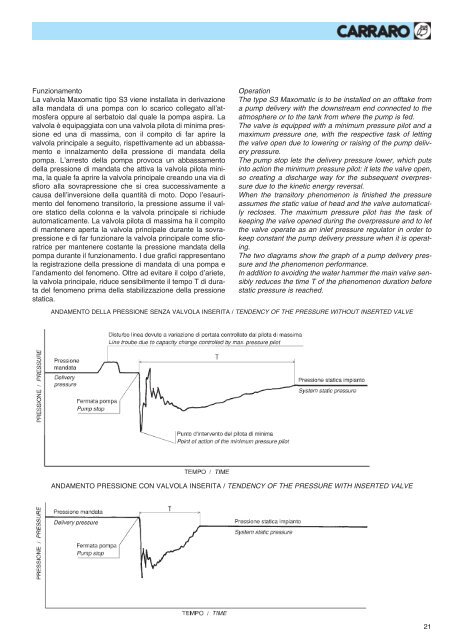
pompa durante il funzionamento. I due grafici rappresentano<br />
la registrazione della pressione di mandata di una pompa e<br />
l’andamento del fenomeno. Oltre ad evitare il colpo d’ariete,<br />
la valvola principale, riduce sensibilmente il tempo T di durata<br />
del fenomeno prima della stabilizzazione della pressione<br />
statica.<br />
Operation<br />
The type S3 Maxomatic is to be installed on an offtake from<br />
a pump delivery with the downstream end connected to the<br />
atmosphere or to the tank from where the pump is fed.<br />
The valve is equipped with a minimum pressure <strong>pilot</strong> and a<br />
maximum pressure one, with the respective task of letting<br />
the valve open due to lowering or raising of the pump delivery<br />
pressure.<br />
The pump stop lets the delivery pressure lower, which puts<br />
into action the minimum pressure <strong>pilot</strong>: it lets the valve open,<br />
so creating a discharge way for the subsequent overpressure<br />
due to the kinetic energy reversal.<br />
When the transitory phenomenon is finished the pressure<br />
assumes the static value of head and the valve automatically<br />
recloses. The maximum pressure <strong>pilot</strong> has the task of<br />
keeping the valve opened during the overpressure and to let<br />
the valve operate as an inlet pressure regulator in order to<br />
keep constant the pump delivery pressure when it is operating.<br />
The two diagrams show the graph of a pump delivery pressure<br />
and the phenomenon performance.<br />
In addition to avoiding the water hammer the main valve sensibly<br />
reduces the time T of the phenomenon duration before<br />
static pressure is reached.<br />
ANDAMENTO DELLA PRESSIONE SENZA VALVOLA INSERITA / TENDENCY OF THE PRESSURE WITHOUT INSERTED VALVE<br />
ANDAMENTO PRESSIONE CON VALVOLA INSERITA / TENDENCY OF THE PRESSURE WITH INSERTED VALVE<br />
21