maxomatic pilot operated control valves
maxomatic pilot operated control valves
maxomatic pilot operated control valves

Create successful ePaper yourself
Turn your PDF publications into a flip-book with our unique Google optimized e-Paper software.
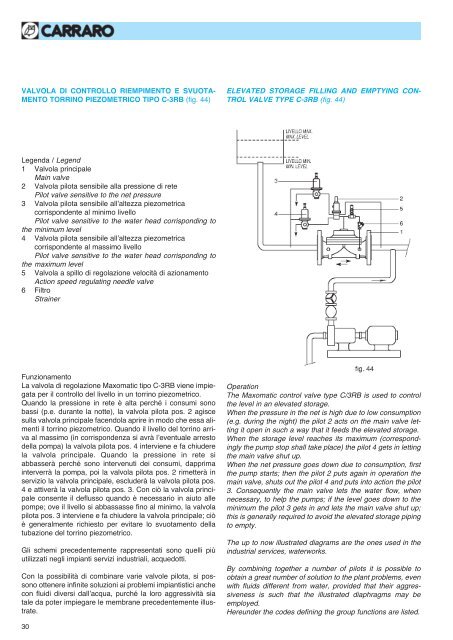
VALVOLA DI CONTROLLO RIEMPIMENTO E SVUOTA-<br />
MENTO TORRINO PIEZOMETRICO TIPO C-3RB (fig. 44)<br />
ELEVATED STORAGE FILLING AND EMPTYING CON-<br />
TROL VALVE TYPE C-3RB (fig. 44)<br />
Legenda / Legend<br />
1 Valvola principale<br />
Main valve<br />
2 Valvola <strong>pilot</strong>a sensibile alla pressione di rete<br />
Pilot valve sensitive to the net pressure<br />
3 Valvola <strong>pilot</strong>a sensibile all’altezza piezometrica<br />
corrispondente al minimo livello<br />
Pilot valve sensitive to the water head corrisponding to<br />
the minimum level<br />
4 Valvola <strong>pilot</strong>a sensibile all’altezza piezometrica<br />
corrispondente al massimo livello<br />
Pilot valve sensitive to the water head corrisponding to<br />
the maximum level<br />
5 Valvola a spillo di regolazione velocità di azionamento<br />
Action speed regulating needle valve<br />
6 Filtro<br />
Strainer<br />
Funzionamento<br />
La valvola di regolazione Maxomatic tipo C-3RB viene impiegata<br />
per il <strong>control</strong>lo del livello in un torrino piezometrico.<br />
Quando la pressione in rete è alta perché i consumi sono<br />
bassi (p.e. durante la notte), la valvola <strong>pilot</strong>a pos. 2 agisce<br />
sulla valvola principale facendola aprire in modo che essa alimenti<br />
il torrino piezometrico. Quando il livello del torrino arriva<br />
al massimo (in corrispondenza si avrà l’eventuale arresto<br />
della pompa) la valvola <strong>pilot</strong>a pos. 4 interviene e fa chiudere<br />
la valvola principale. Quando la pressione in rete si<br />
abbasserà perché sono intervenuti dei consumi, dapprima<br />
interverrà la pompa, poi la valvola <strong>pilot</strong>a pos. 2 rimetterà in<br />
servizio la valvola principale, escluderà la valvola <strong>pilot</strong>a pos.<br />
4 e attiverà la valvola <strong>pilot</strong>a pos. 3. Con ciò la valvola principale<br />
consente il deflusso quando è necessario in aiuto alle<br />
pompe; ove il livello si abbassasse fino al minimo, la valvola<br />
<strong>pilot</strong>a pos. 3 interviene e fa chiudere la valvola principale; ciò<br />
è generalmente richiesto per evitare lo svuotamento della<br />
tubazione del torrino piezometrico.<br />
Gli schemi precedentemente rappresentati sono quelli più<br />
utilizzati negli impianti servizi industriali, acquedotti.<br />
Con la possibilità di combinare varie valvole <strong>pilot</strong>a, si possono<br />
ottenere infinite soluzioni ai problemi impiantistici anche<br />
con fluidi diversi dall’acqua, purché la loro aggressività sia<br />
tale da poter impiegare le membrane precedentemente illustrate.<br />
Operation<br />
The Maxomatic <strong>control</strong> valve type C/3RB is used to <strong>control</strong><br />
the level in an elevated storage.<br />
When the pressure in the net is high due to low consumption<br />
(e.g. during the night) the <strong>pilot</strong> 2 acts on the main valve letting<br />
it open in such a way that it feeds the elevated storage.<br />
When the storage level reaches its maximum (correspondingly<br />
the pump stop shall take place) the <strong>pilot</strong> 4 gets in letting<br />
the main valve shut up.<br />
When the net pressure goes down due to consumption, first<br />
the pump starts; then the <strong>pilot</strong> 2 puts again in operation the<br />
main valve, shuts out the <strong>pilot</strong> 4 and puts into action the <strong>pilot</strong><br />
3. Consequently the main valve lets the water flow, when<br />
necessary, to help the pumps; if the level goes down to the<br />
minimum the <strong>pilot</strong> 3 gets in and lets the main valve shut up;<br />
this is generally required to avoid the elevated storage piping<br />
to empty.<br />
The up to now illustrated diagrams are the ones used in the<br />
industrial services, waterworks.<br />
By combining together a number of <strong>pilot</strong>s it is possible to<br />
obtain a great number of solution to the plant problems, even<br />
with fluids different from water, provided that their aggressiveness<br />
is such that the illustrated diaphragms may be<br />
employed.<br />
Hereunder the codes defining the group functions are listed.<br />
30