maxomatic pilot operated control valves
maxomatic pilot operated control valves
maxomatic pilot operated control valves

You also want an ePaper? Increase the reach of your titles
YUMPU automatically turns print PDFs into web optimized ePapers that Google loves.
FUNZIONAMENTO<br />
Gli organi essenziali per il funzionamento del gruppo di regolazione<br />
sono la membrana, la molla conica e il sistema <strong>pilot</strong>a.<br />
Quest’ultimo utilizza il liquido regolato come servofluido,<br />
facendo variare, in fase di regolazione, la sua pressione nella<br />
camera sopra la membrana. Questa funge contemporaneamente<br />
da otturatore e, assieme alla molla, da attuatore. La<br />
sua sagomatura le consente di assumere posizioni intermedie<br />
fra quella di totale chiusura e quella di massima apertura,<br />
e di fermarsi stabilmente in quella posizione che sia richiesta<br />
da un certo regime di esercizio. La posizione, sia in condizioni<br />
di regime, sia in fase di regolazione, è determinata<br />
dall’equilibrio delle forze agenti sopra e sotto la membrana e<br />
dovute alle pressioni del liquido, alla molla e alle azioni<br />
dinamiche. Il <strong>pilot</strong>a sensibile al parametro <strong>control</strong>lato, agisce<br />
sul flusso del servofluido, in modo da variare la pressione<br />
sulla membrana, perché essa si muova adeguando il grado<br />
di apertura alla portata richiesta, per mantenere costante il<br />
parametro <strong>control</strong>lato. Quando la valvola si è portata al grado<br />
di apertura necessario, la valvola <strong>pilot</strong>a riassetta in modo da<br />
stabilizzare come occorre il flusso di <strong>control</strong>lo, realizzando<br />
così la sua azione integrale.<br />
OPERATION<br />
The essential parts for the operation of the regulating device<br />
are the diaphragm, the conical spring and the <strong>pilot</strong> system.<br />
The diaphragm acts at the same time as a shutter and,<br />
together with the spring, as an actuator. Its shaping allows it<br />
to be brought in any position from totally close to fully open<br />
position without any particular strain. Its position is determined<br />
by a balance of the forces, due, in the closing direction,<br />
to the combined actions of the spring and the servofluid<br />
(which is the medium itself) acting on the diaphragm with<br />
pressure <strong>valves</strong> conveniently rated by the <strong>pilot</strong> system; and<br />
in the opening direction to the pressure of the medium acting<br />
on the lower diaphragm surface. The conical spring makes<br />
up or returns a force more than proportional to the diaphragm<br />
lift, and so increasing in correspondence with the dynamic<br />
forces acting on the diaphragm; it is therefore ready, when<br />
the servofluid pressure changes, to give up forces adequate<br />
for the proportional action, without chattering. The <strong>pilot</strong>, sensing<br />
the <strong>control</strong>led parameter, acts on the servofluid flow so as<br />
to charge the pressure on the diaphragm, in the direction<br />
required, to make it move in such a way that the valve lift corresponds<br />
to the opening required to keep the <strong>control</strong>led<br />
parameter constant. When the valve has reached the operating<br />
corresponding to the required capacity, the <strong>pilot</strong> resets,<br />
so as to let flow the same capacity as before the <strong>control</strong>ling<br />
action, thus carrying out its integral action.<br />
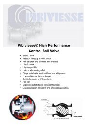
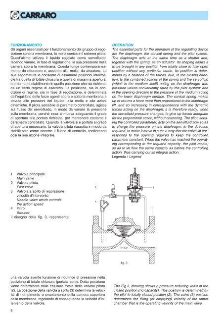
Legenda / Legend<br />
1 Valvola principale<br />
Main valve<br />
2 Valvola <strong>pilot</strong>a<br />
Pilot valve<br />
3 Valvola a spillo di regolazione<br />
velocità d’intervento<br />
Needle valve which <strong>control</strong>s<br />
the action speed<br />
4 Filtro<br />
Strainer<br />
Il disegno della fig. 3, rappresenta<br />
una valvola avente funzione di riduttrice di pressione nella<br />
posizione di totale chiusura (portata zero). Detta posizione<br />
viene determinata dalla chiusura totale della valvola <strong>pilot</strong>a<br />
(2). La posizione della valvola a spillo (3) determina la velocità<br />
di riempimento e svuotamento della camera superiore<br />
della membrana, regolando di conseguenza la velocità d’intervento<br />
della valvola.<br />
The Fig.3, drawing shows a pressure reducing valve in the<br />
closed position (no capacity). This position is determined by<br />
the <strong>pilot</strong> in totally closed position (2). The valve (3) position<br />
determines the filling (or emptying) velocity of the upper<br />
chamber that is the operating velocity of the main valve.<br />
6