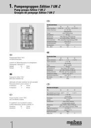
2. Pumpengruppen MK - Meibes
2. Pumpengruppen MK - Meibes
2. Pumpengruppen MK - Meibes

Create successful ePaper yourself
Turn your PDF publications into a flip-book with our unique Google optimized e-Paper software.
8. Gravity brake<br />
The gravity brake and/or check valves used in our systems are specifically marked. They are integrated into the ball valve. The handle is<br />
labelled with „SB”. The gravity brake can be de-activated by turning the handle approx. 45° to the stop position - “Anschlagstellung”.<br />
see Fig. 7. and 7.2<br />
9. Instructions for the proper and functional operation of the heating<br />
system<br />
Note!<br />
After filling and pressure testing the system open the ball valve of the return first. This will protect the gravity brake in the return circuit from<br />
being damaged by a shock wave (over pressure in system).<br />
see Fig. 8<br />
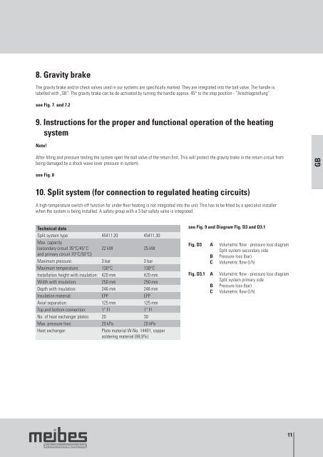
10. Split system (for connection to regulated heating circuits)<br />
A high-temperature switch-off function for under-floor heating is not integrated into the unit. This has to be fitted by a specialist installer<br />
when the system is being installed. A safety group with a 3 bar safety valve is integrated.<br />
Technical data<br />
Split system type:<br />
Max. capacity<br />
45411.20 45411.30<br />
(secondary circuit 35°C/45°C<br />
and primary circuit 70°C/50°C):<br />
22 kW 25 kW<br />
Maximum pressure: 3 bar 3 bar<br />
Maximum temperature: 130°C 130°C<br />
Installation height with insulation: 420 mm 420 mm<br />
Width with insulation: 250 mm 250 mm<br />
Depth with insulation: 246 mm 246 mm<br />
Insulation material: EPP EPP<br />
Axial separation: 125 mm 125 mm<br />
Top and bottom connection: 1“ FI 1“ FI<br />
No. of heat exchanger plates: 20 30<br />
Max. pressure loss: 20 kPa 20 kPa<br />
Heat exchanger: Plate material W-No. 14401, copper<br />
soldering material (99,9%)<br />
see Fig. 9 and Diagram Fig. D3 and D3.1<br />
Fig. D3 A Volumetric flow - pressure loss diagram<br />
Split system secondary side<br />
B Pressure loss (bar)<br />
C Volumetric flow (l/h)<br />
Fig. D3.1 A Volumetric flow - pressure loss diagram<br />
Split system primary side<br />
B Pressure loss (bar)<br />
C Volumetric flow (l/h)<br />
11<br />
GB