2. Pumpengruppen MK - Meibes
2. Pumpengruppen MK - Meibes
2. Pumpengruppen MK - Meibes

You also want an ePaper? Increase the reach of your titles
YUMPU automatically turns print PDFs into web optimized ePapers that Google loves.
12<br />
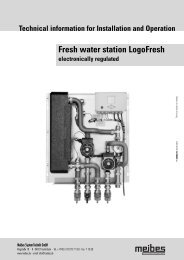
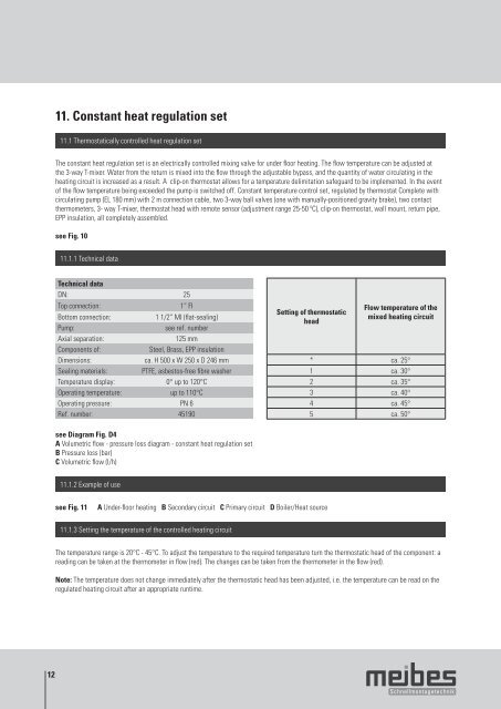
11. Constant heat regulation set<br />
11.1 Thermostatically controlled heat regulation set<br />
The constant heat regulation set is an electrically controlled mixing valve for under floor heating. The flow temperature can be adjusted at<br />
the 3-way T-mixer. Water from the return is mixed into the flow through the adjustable bypass, and the quantity of water circulating in the<br />
heating circuit is increased as a result. A clip-on thermostat allows for a temperature delimitation safeguard to be implemented. In the event<br />
of the flow temperature being exceeded the pump is switched off. Constant temperature control set, regulated by thermostat Complete with<br />
circulating pump (EL 180 mm) with 2 m connection cable, two 3-way ball valves (one with manually-positioned gravity brake), two contact<br />
thermometers, 3- way T-mixer, thermostat head with remote sensor (adjustment range 25-50 ºC), clip-on thermostat, wall mount, return pipe,<br />
EPP insulation, all completely assembled.<br />
see Fig. 10<br />
11.1.1 Technical data<br />
Technical data<br />
DN: 25<br />
Top connection: 1“ FI<br />
Bottom connection: 1 1/2“ MI (flat-sealing)<br />
Pump: see ref. number<br />
Axial separation: 125 mm<br />
Components of: Steel, Brass, EPP insulation<br />
Dimensions: ca. H 500 x W 250 x D 246 mm<br />
Sealing materials: PTFE, asbestos-free fibre washer<br />
Temperature display: 0° up to 120°C<br />
Operating temperature: up to 110°C<br />
Operating pressure: PN 6<br />
Ref. number: 45190<br />
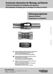
see Diagram Fig. D4<br />
A Volumetric flow - pressure loss diagram - constant heat regulation set<br />
B Pressure loss (bar)<br />
C Volumetric flow (l/h)<br />
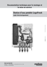
11.1.2 Example of use<br />
see Fig. 11 A Under-floor heating B Secondary circuit C Primary circuit D Boiler/Heat source<br />
11.1.3 Setting the temperature of the controlled heating circuit<br />
Setting of thermostatic<br />
head<br />
Flow temperature of the<br />
mixed heating circuit<br />
* ca. 25°<br />
1 ca. 30°<br />
2 ca. 35°<br />
3 ca. 40°<br />
4 ca. 45°<br />
5 ca. 50°<br />
The temperature range is 20°C - 45°C. To adjust the temperature to the required temperature turn the thermostatic head of the component: a<br />
reading can be taken at the thermometer in flow (red). The changes can be taken from the thermometer in the flow (red).<br />
Note: The temperature does not change immediately after the thermostatic head has been adjusted, i.e. the temperature can be read on the<br />
regulated heating circuit after an appropriate runtime.