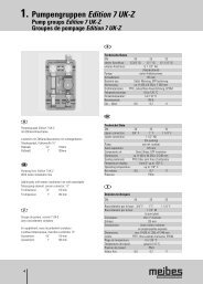
2. Pumpengruppen MK - Meibes
2. Pumpengruppen MK - Meibes
2. Pumpengruppen MK - Meibes

You also want an ePaper? Increase the reach of your titles
YUMPU automatically turns print PDFs into web optimized ePapers that Google loves.
14<br />
1<strong>2.</strong> Return temperature limiter system<br />
1<strong>2.</strong>1. Return flow heat regulation system DN 25 (1”) thermostatically controlled<br />
The return flow heat regulation system is mounted beneath the manifold joint. Depending on the return temperature, the flow is mixed to the<br />
return. The result is a shorter heating-up time and it prevents the combustion chamber from condensation. The required return temperature<br />
can be set via the thermostat or the electrical regulator on the 3-way T- mixer. The minimum return temperature dependents on the type of<br />
boiler used.<br />
see Fig. 13<br />
1<strong>2.</strong>1.1 Return temperature limiter system – technical data<br />
Technical data<br />
DN: 25<br />
Top connection: manifold connection 1 1/2“ FI<br />
Bottom connection: Boiler connection 1“ FI (flat-sealing)<br />
Pump: see ref. number<br />
Axial separation: 125 mm<br />
Components of: Brass, EPP-insulation<br />
Dimensions: ca. H 420 x W 250 x D 246 mm<br />
Sealing materials: PTFE, fiber joint free of astbestos, EPDM<br />
Temperature display: 0° up to 120°C<br />
Operating temperature: up to 110°C<br />
Operating pressure: PN 6<br />
Ref. number: 45441<br />
1<strong>2.</strong>1.3 Adjusting the return temperature<br />
The temperature range is 40°C - 70°C. The required temperature of the mixed circuit can be set at the top of the component’s thermostat and<br />
can be read from the thermometer in the return flow (blue).<br />
Note: The temperature does not change immediately after the thermostatic head has been adjusted, i.e. the temperature can be read on the<br />
regulated heating circuit after an appropriate runtime.<br />
1<strong>2.</strong><strong>2.</strong> Return flow heat regulator DN 25 (1”) electrically controlled<br />
Technical data<br />
DN:<br />
Upper/Hot Top/hot boiler boiler connection:<br />
Lower/boiler Bottom boiler connection:<br />
Pump:<br />
Axial separation:<br />
Components of:<br />
Dimensions:<br />
Sealing materials:<br />
Temperature display:<br />
Usage range (max.):<br />
Operational pressure:<br />
25<br />
1 1/2“ FI (flat-sealing)<br />
1“ FI<br />
see ref. number<br />
125 mm<br />
Brass, EPP insulation<br />
ca. H 500 x W 250 x D 250 mm<br />
PTFE, asbestos-free fibre sealing, EPDM<br />
0° up to 120°C<br />
up to 110°C<br />
PN 6<br />
see Diagram Fig. D5<br />
Fig. D5 A Volumetric flow - pressure loss<br />
diagram – return flow heat<br />
regulation<br />
B Pressure loss (bar)<br />
C Volumetric flow (l/h)<br />
1<strong>2.</strong>1.2 Example of use<br />
see Fig. 14 A Boiler/Heat source<br />
Design ref. number<br />
1“ without pump 45441.5 EA<br />
1“ with GRUNDFOS pump UPS<br />
25-40/180<br />
45441.5<br />
1“ with WILO pump STAR-RS 25/4 45441.5 WI<br />
see Fig. 14.1