Tema d'esame del 21 luglio 2011 - Costruzione di Macchine 2
Tema d'esame del 21 luglio 2011 - Costruzione di Macchine 2
Tema d'esame del 21 luglio 2011 - Costruzione di Macchine 2

You also want an ePaper? Increase the reach of your titles
YUMPU automatically turns print PDFs into web optimized ePapers that Google loves.
Politecnico <strong>di</strong> Milano - Corso <strong>di</strong> Laurea in Ingegneria Meccanica<br />
Anno accademico 2010-11<br />
<strong>Costruzione</strong> <strong>di</strong> <strong>Macchine</strong> 2<br />
(Prof. S. Beretta, Prof. L. Vergani)<br />
<strong>Tema</strong> d’esame: <strong>21</strong> <strong>luglio</strong> <strong>2011</strong><br />
NOME :<br />
COGNOME :<br />
MATRICOLA :<br />
SPAZIO RISERVATO AL DOCENTE:<br />
1<br />
2<br />
Totale<br />
NOTA: Le risposte agli esercizi vanno riportate esclusivamente sul foglio consegnato.<br />
Esercizio 1.<br />
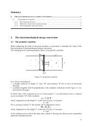
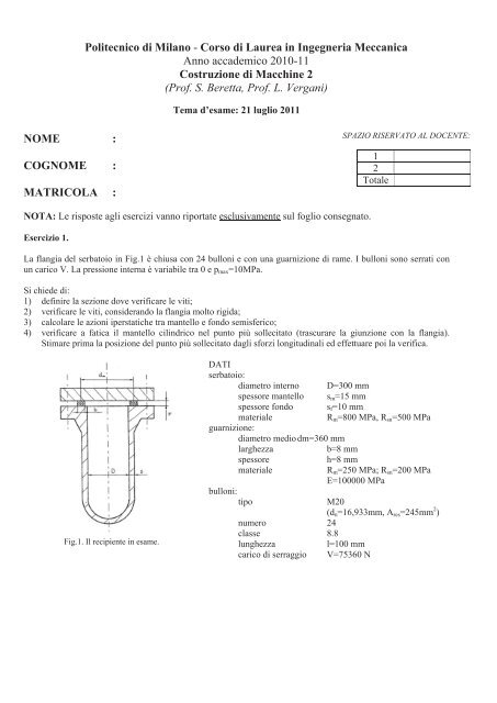
La flangia <strong>del</strong> serbatoio in Fig.1 è chiusa con 24 bulloni e con una guarnizione <strong>di</strong> rame. I bulloni sono serrati con<br />
un carico V. La pressione interna è variabile tra 0 e p max =10MPa.<br />
Si chiede <strong>di</strong>:<br />
1) definire la sezione dove verificare le viti;<br />
2) verificare le viti, considerando la flangia molto rigida;<br />
3) calcolare le azioni iperstatiche tra mantello e fondo semisferico;<br />
4) verificare a fatica il mantello cilindrico nel punto più sollecitato (trascurare la giunzione con la flangia).<br />
Stimare prima la posizione <strong>del</strong> punto più sollecitato dagli sforzi longitu<strong>di</strong>nali ed effettuare poi la verifica.<br />
Fig.1. Il recipiente in esame.<br />
DATI<br />
serbatoio:<br />
<strong>di</strong>ametro interno D=300 mm<br />
spessore mantello s m =15 mm<br />
spessore fondo s f =10 mm<br />
materiale<br />
R m =800 MPa, R sn =500 MPa<br />
guarnizione:<br />
<strong>di</strong>ametro me<strong>di</strong>o dm=360 mm<br />
larghezza<br />
b=8 mm<br />
bulloni:<br />
tipo<br />
spessore<br />
materiale<br />
numero 24<br />
classe 8.8<br />
lunghezza<br />
l=100 mm<br />
carico <strong>di</strong> serraggio V=75360 N<br />
h=8 mm<br />
R m =250 MPa; R sn =200 MPa<br />
E=100000 MPa<br />
M20<br />
(d n =16,933mm, A res =245mm 2 )
Esercizio 2.<br />
In Fig.2 è mostrata una struttura con una trave vincolata alle sue estremità A con un incastro e B con un carrello.<br />
Sopra la trave è posizionato un carrello con un peso P. Il carrello può traslare orizzontalmente.<br />
Si richiede <strong>di</strong>:<br />
1) determinare l’andamento <strong>del</strong>le reazioni all’incastro A <strong>del</strong>la trave in funzione <strong>del</strong>la posizione orizzontale x 0 <strong>del</strong><br />
carrello, eventualmente con uno stu<strong>di</strong>o per punti;<br />
2) <strong>di</strong>mensionare la saldatura <strong>del</strong>la piastra in modo da verificarne la resistenza statica.<br />
y<br />
A<br />
P<br />
B<br />
y<br />
x<br />
z<br />
l<br />
x 0<br />
DATI<br />
Tipo <strong>di</strong> trave: HEA200<br />
Piastra: quadrata, 300x300 mm, materiale: Fe430<br />
P = 25000 N<br />
l = 4000 mm<br />
Fig.1. Schema <strong>del</strong>la trave e <strong>del</strong>la sua sezione <strong>di</strong> incastro (A).