MULTIBODY DYNAMICS 2007, ECCOMAS Thematic ... - BBAA VI
MULTIBODY DYNAMICS 2007, ECCOMAS Thematic ... - BBAA VI
MULTIBODY DYNAMICS 2007, ECCOMAS Thematic ... - BBAA VI

You also want an ePaper? Increase the reach of your titles
YUMPU automatically turns print PDFs into web optimized ePapers that Google loves.
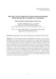
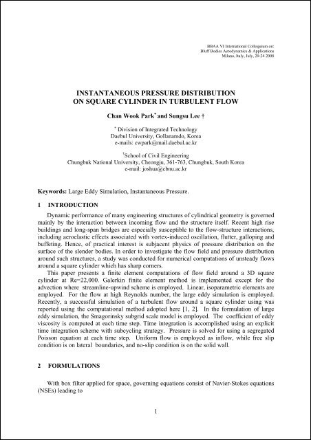
<strong>BBAA</strong> <strong>VI</strong> International Colloquium on:Bluff Bodies Aerodynamics & ApplicationsMilano, Italy, July, 20-24 2008INSTANTANEOUS PRESSURE DISTRIBUTIONON SQUARE CYLINDER IN TURBULENT FLOWChan Wook Park ∗ and Sungsu Lee †∗ Division of Integrated TechnologyDaebul University, Gollanamdo, Koreae-mails: cwpark@mail.daebul.ac.kr† School of Civil EngineeringChungbuk National University, Cheongju, 361-763, Chungbuk, South Koreae-mail: joshua@cbnu.ac.krKeywords: Large Eddy Simulation, Instantaneous Pressure.1 INTRODUCTIONDynamic performance of many engineering structures of cylindrical geometry is governedmainly by the interaction between incoming flow and the structure itself. Recent high risebuildings and long-span bridges are especially susceptible to the flow-structure interactions,including aeroelastic effects associated with vortex-induced oscillation, flutter, galloping andbuffeting. Hence, of practical interest is subjacent physics of pressure distribution on thesurface of the slender bodies. In order to investigate the flow field and pressure distributionaround such structures, a study was conducted for numerical computations of unsteady flowsaround a square cylinder which has sharp corners.This paper presents a finite element computations of flow field around a 3D squarecylinder at Re=22,000. Galerkin finite element method is implemented except for theadvection where streamline-upwind scheme is employed. Linear, isoparametric elements areemployed. For the flow at high Reynolds number, the large eddy simulation is employed.Recently, a successful simulation of a turbulent flow around a square cylinder using wasreported using the computational method adopted here [1, 2]. In the formulation of largeeddy simulation, the Smagorinsky subgrid scale model is employed. The coefficient of eddyviscosity is computed at each time step. Time integration is accomplished using an explicittime integration scheme with subcycling strategy. Pressure is solved for using a segregatedPoisson equation at each time step. Uniform flow is employed as inflow, while free slipcondition is on lateral boundaries, and no-slip condition is on the solid wall.2 FORMULATIONSWith box filter applied for space, governing equations consist of Navier-Stokes equations(NSEs) leading to1
Chan-Wook Park and Sungsu Lee∂ui∂t∂u∂Pν ∂ S ∂τi 1 $ij ij+ uj= − + −∂xρ ∂x∂x∂xjwhere* *$ τij = τij − 1 3 δijτkk , P = p+ 1 ij3 τ * kk(2)ijSmagorinsky model based on the eddy viscosity concept and the mixing length theory isemployed, where the eddy viscosity concept leads to the following model:$ τ =−2 ν S . (3)ij SGS ijwhere ν SGS is the eddy viscosity for LES which has the form of( C )ν SGS SS ij ijijj(1)= Δ 2 2 S (4)where C S is the Smagorinsky constant set to 0.1 in this study.Applying GFEM with isoparametric elements to governing equations results in thefollowing algebraic equations.MV& + K(V)V − CP = Q and CT V = 0(5)where V is a global velocity vector, P is a global pressure vector, and Q is a force vectorincorporating the velocity natural boundary conditions. M is the mass matrix and K containsthe advection and the diffusion terms. C is the gradient matrix while its transpose, C T is thedivergence matrix. The Reynolds SGS stress term is included in K and the eddyviscosityν SGSis evaluated at the centroid of each element, at each time step. Explicit (Euler)method is employed for time integration, which a Poisson equation is solved for the pressurefield at each time step, and the initial flow field is set to zero except for the inflow boundary,and it is next modified to satisfy the continuity equation by solving an auxiliary Poissonequation. Fig (1) depicts the computational domain employed in this study. No-slip on thesolid wall and traction free on the outflow boundary are imposed.3 PRESSURE FIELDFigure 1: Computational DomainIn order to verify the computational results of the present study, integral parameters arecompared with others in Table (1). The computation results in 0.134 as the Strouhal numbersfound at the frequency where the peak of the spectral distribution of lift coefficient is located.It is close to the experimental value of 0.13 measured by Lin et al [5,6]. The drag coefficientis 2.06 and the time-averaged lift coefficient predicted is O(10 -2 ). These results are in goodagreement with other experimental and computational data.In order to investigate the instantaneous flow field around the square cylinder, fiverepresentative instances were defined using lift coefficients. Those instants were referred to a‘Frames’ and depicted in Fig (2). Fig (3) shows the contour plots of instantaneous pressurecoefficients on the surfaces of the square cylinder at the instant corresponding to Frame 5 in2
Chan-Wook Park and Sungsu LeeFig (2). Each plot corresponds to a side of the square cylinder as depicted in a small diagram.Apparently the pressure on the lower surface is higher than that on the upper surface,resulting in positive lift (frame 5). Close to the windward corners, concentrations of pressuregradients of large magnitude are observed. Pressure distribution on the windward face isfairly uniform in spanwise direction (z) due to the uniformity of inflow. A mild uniformity ofpressure is exhibited on the lower surface where the pressure is higher than that on the uppersurface, whereas a large area of low pressure is seen on the upper surface. On the other hand,relatively large changes of pressure distribution in the z-direction are shown on the leewardface due to the three-dimensional characteristics of vortex shedding behind the cylinder.Cases Re St C D (C L ) rms l rMean rmsPresent 3D LES (SM) FEM 22000 0.134 2.06 0.33 1.214 0.75(47760)Murakami and 3D LES (SM) FDM 22000 0.132 2.09 - - 0.64Mochida[3](71760)Lyn et al [4,5] Experiment 9.75 21400 0.132-0.1342.1 - - 0.88Table 1: Comparison of integral parameters.Figure 2: Definition of frames in instantaneous flow field.It is well recognized that random reattachments of a separated shear layer createsintermittent recirculation regions on the upper and lower walls of the cylinder where lowerpressure is expected. In order to investigate this feature, instantaneous flow fields adjacent tothe cylinder and pressure distributions on the surface were considered.A sequence of pressure distributions on the upper wall of the cylinder is shown in Fig (4),each of which corresponds to the frames 1 and 5. The figures also include surface-elevatedplots of horizontal velocity and contour plots of lateral velocity adjacent to the surface. In thesurface-elevated plots in Fig (4), positive values are flattened out so that the recirculationregions can be visualized.In the surface-elevated plots of negative horizontal velocity, contours with thick solid lineindicates the boundary of the recirculation regions. For all the frames considered here, a largemagnitude of negative horizontal velocity is observed close to the windward corners,indicating separation of the incoming flow. The separation is often followed by immediatereattachment resulting in a large gradient of pressure, depending on the spanwise location.Comparing the surface-elevated plots with the pressure contours, the high pressure zone isseen in the region where reattachment occurs. Local detachment of the reattached flow isalso observed. The variation of the surface-elevated plots in time and space does not showany particular patterns and confirms that the process of reattachment and detachment israndom and intermittent.4 CONCLUSIONIn order to understand the correlation of surface pressure and flow field, large eddysimulation of 3D turbulent flow around a square cylinder was carried out. The simulatedthree-dimensional distributions of the pressure on the surface of the cylinder showed the3
Chan-Wook Park and Sungsu Leenonuniformity of the pressure field in the spanwise direction. Random and intermittentprocesses of reattachment and detachment of the separated shear layer on the cylinder surfacewere identified, and the reattachment was shown to be responsible for the increase in localpressure. A spanwise correlation of the simulated pressure field was compared to theavailable experimental data and showed reasonable agreement. In addition, an intermittentreattachment of short recirculation length was shown to be responsible for large negativepressure on the surface.z/H0.0 0.5 1.0 1.5 2. 04.0 (0.0)3.5Leeward FaceHorizontal VelocityHorizontal Velocity3.03.02.5Upper Surface2.0Spanwise Velocity(+w)Spanwise Velocity(-w)2.0(+w)(-w)1.5Windward Face1.01.0Pressure CoefficientPressure Coefficient2 3Inflow1 0 (4)ss/H0.5Lower Surface0.00.0 0.5 1.0 1.5 2.0z/HFigure 3: Instantaneous pressure at frame 5Figure 4: Instantaneous pressure and velocity on upper wallACKNOWLEDGEMENTSThis work was supported by the grant from Underwater Vehicle Research Center andAgency for Defence Development, South Korea.REFERENCES[1] S. Lee, Large eddy simulation of flow past a square cylinder using finite elementmethod, Ph.D Dissertation, Colorado State University, Ft. Collins, USA, 1997.[2] S. Lee, Numerical study of wake structure behind a square cylinder at high Reynoldsnumber, Wind and Structures, Int. J., vol.1, no.2, pp.127-144. 1998.[3] S. Murakami, A. Mochida and K. Hibi, Three-dimensional numerical simulation of airflow around a cubic model by means of large eddy simulation J. Wind Eng. Ind.Aerodyn., Vol. 25, 1987, pp.291-305.[4] D.A. Lyn and W. Rodi,The flapping shear layer formed by flow separation from theforward corner of a square cylinder, J. Fluid Mech., vol. 267, 1994, pp.353-376.[5] D.A. Lyn, S. Einav, W. Rodi, and J.-H. Park, A laser-Doppler velocimeter study ofensemble-averaged characteristics of the turbulent near wake of a square cylinder, J.Fluid Mech., vol. 304, 1995, pp.285-319.4