AERODYNAMIC DESIGN OF A FORMULA SAE RACE CAR - BBAA VI
AERODYNAMIC DESIGN OF A FORMULA SAE RACE CAR - BBAA VI
AERODYNAMIC DESIGN OF A FORMULA SAE RACE CAR - BBAA VI
- No tags were found...

You also want an ePaper? Increase the reach of your titles
YUMPU automatically turns print PDFs into web optimized ePapers that Google loves.
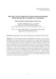
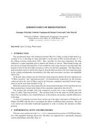
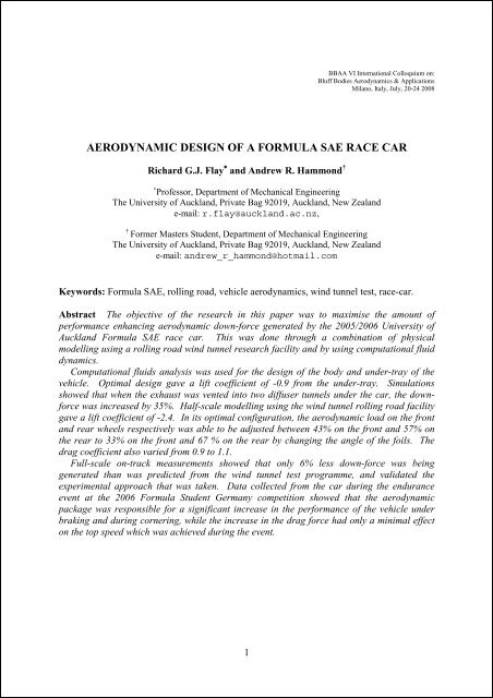
<strong>BBAA</strong> <strong>VI</strong> International Colloquium on:Bluff Bodies Aerodynamics & ApplicationsMilano, Italy, July, 20-24 2008<strong>AERODYNAMIC</strong> <strong>DESIGN</strong> <strong>OF</strong> A <strong>FORMULA</strong> <strong>SAE</strong> <strong>RACE</strong> <strong>CAR</strong>Richard G.J. Flay ∗ and Andrew R. Hammond †∗ Professor, Department of Mechanical EngineeringThe University of Auckland, Private Bag 92019, Auckland, New Zealande-mail: r.flay@auckland.ac.nz,†Former Masters Student, Department of Mechanical EngineeringThe University of Auckland, Private Bag 92019, Auckland, New Zealande-mail: andrew_r_hammond@hotmail.comKeywords: Formula <strong>SAE</strong>, rolling road, vehicle aerodynamics, wind tunnel test, race-car.Abstract The objective of the research in this paper was to maximise the amount ofperformance enhancing aerodynamic down-force generated by the 2005/2006 University ofAuckland Formula <strong>SAE</strong> race car. This was done through a combination of physicalmodelling using a rolling road wind tunnel research facility and by using computational fluiddynamics.Computational fluids analysis was used for the design of the body and under-tray of thevehicle. Optimal design gave a lift coefficient of -0.9 from the under-tray. Simulationsshowed that when the exhaust was vented into two diffuser tunnels under the car, the downforcewas increased by 35%. Half-scale modelling using the wind tunnel rolling road facilitygave a lift coefficient of -2.4. In its optimal configuration, the aerodynamic load on the frontand rear wheels respectively was able to be adjusted between 43% on the front and 57% onthe rear to 33% on the front and 67 % on the rear by changing the angle of the foils. Thedrag coefficient also varied from 0.9 to 1.1.Full-scale on-track measurements showed that only 6% less down-force was beinggenerated than was predicted from the wind tunnel test programme, and validated theexperimental approach that was taken. Data collected from the car during the enduranceevent at the 2006 Formula Student Germany competition showed that the aerodynamicpackage was responsible for a significant increase in the performance of the vehicle underbraking and during cornering, while the increase in the drag force had only a minimal effecton the top speed which was achieved during the event.1
Richard G.J. Flay, and Andrew R. Hammond1 INTRODUCTIONThe Formula <strong>SAE</strong> competition was established in 1981 by the Society of AutomotiveEngineers (<strong>SAE</strong>) in the United States of America as an educational tool to develop theknowledge and skill base of the automotive industry at the University level. The competitionrequires that each team from their respective universities design, build, and test a small, openwheeled,single-seater race-car with the premise that a manufacturing firm has employed theteam to design the vehicle for a one-make racing series, for which the cost to reproduce eachof the vehicles must not exceed US$25,000. The competition comprises both static anddynamic events. The static events consist of a business and design presentation each of whichare marked by a panel of experts. A tilt test of the vehicle is also performed to simulatecornering and the determination of the height of the centre of gravity of the vehicle. Thedynamic events aim to test the vehicle in all aspects of competition car performance withacceleration, skid pan cornering, autocross and a final twenty-two kilometre endurance test.Marks are awarded for the performance of the vehicle in each of these tests as well as on thefuel economy of the vehicle during the endurance event. The total marks received from boththe static and the dynamic events determine the overall winner of the competition.Aerodynamic downforce is hugely exploited in the design of the modern race car (Refs.[1][2]). The performance benefits which can be gained through the resulting increase intraction has made the search for increased downforce and reduced drag a highly sought afterperformance edge in motorsport. The benefits of downforce and effective aerodynamic designin the Formula <strong>SAE</strong> car, however, were not entirely clear. It was the goal of the presentresearch to determine areas where the aerodynamic forces are most performance enhancing byutilising CFD as well as model testing in a wind tunnel equipped with a moving belt groundplane, and then to validate the predictions using on-road measurements. Further details areavailable in Ref. [3].2 NUMERICAL MODELLINGThe purpose of the CFD analysis was primarily to design the body (including side pods) andthe under-tray of the vehicle prior to carrying out wind tunnel testing. The CAD models ofthe car body and under-tray were constructed using ProEngineer Wildfire 2.0, the-0.8Lift coefficient-1ExhaustTemp. 300CExhaustTemp. 450CExhaustTemp. 600C-1.20 0.02 0.04 0.06Exhaust mass flow rate, kg/sFigure 1: Effect of rear diffuser tunnelexhaust mass flow rate and gas temperatureon the lift coefficientFigure 1 Photograph of half-scale modelmounted in wind tunnel above moving beltground plane2
Richard G.J. Flay, and Andrew R. Hammondcomputational domain was meshed using ICEM CFD mesh builder, and the CFD analysis wascarried out using the CFX 5.6 Pre, Solver and Post programs. To get the maximumperformance from the available software and hardware, a computational half-model was used(cut along the longitudinal centreline) 13m long, 3m wide, and 2.5m high, giving a blockageof 3.7%, or in terms of the model maximum dimensions: l, w, h: 4.56 x l, 4.69 x w and 3.56 xh. A mesh refinement study was conducted and it was determined, given the computationalpower available, that the optimal mesh for the study of the body and under-tray consisted ofapproximately 1.5 million cells. The surface of the model was given an inflated meshconsisting of five layers of inflation with an expansion rate of 1.2 between each layer. Theremainder of the mesh was generated using tetrahedral cells with a minimum edge length of1.4mm and a maximum of 106mm. The software solved the Reynolds Averaged NavierStokes (RANS) equations, using the Shear-Stress-Transport (SST) turbulence model.As an example of a typical result obtained, the effect of directing the exhaust gases into therear diffuser tunnels under the car on the lift coefficient for a number of exhaust gastemperatures was investigated, and the results are shown in Fig. (1) for a vehicle speed of 15m/s. It is clearly evident that the downforce is increased as the mass flow rate and gastemperature increase.3 WIND TUNNEL TESTINGThe wind tunnel testing was carried out in the University of Auckland’s Twisted FlowWind Tunnel, with the twisting vanes removed, and the walls contoured into a contraction toform an open jet of size 3.5 x 3.5 m 2 . In addition, a moving belt 1.6m wide and 3m longdriven by an electric motor was used to provide the correct boundary condition at the groundby being driven at the same speed as the onset air flow. A half-scale model made of carbonfibre was used for the testing. It was attached to the under-floor wind tunnel balance. The carwheels were not attached to the car model, but were positioned accurately and spun by thebelt action. A photograph of the model mounted above the belt is given in Fig. (2). The flowquality above the belt was examined by performing many velocity profiles. There is notspace in this abstract to include those profiles.CoP - distance from rear axle0.40.30.20.140 60 80Flap Position, degreesFigure 3: Rear wing height Effect on centre of pressure495mm (Front Wing with ThirdElement With all Accessorieswith no Rear Wing Gurney Flap)495mm (Front Wing with ThirdElement With Endplate Flaps,Central Gurney Flap and 3rdSecond Element)495mm (Front Wing with ThirdElement No Accessories)525mm (Front Wing with ThirdElement With all Accessories)495mm (With Endplate Flaps,Central Gurney Flap and 3rdSecond Element)495mm3
Richard G.J. Flay, and Andrew R. HammondA large amount of wind tunnel testing was carried out including: independent front andrear wing testing, evaluation of Reynolds number effects on the half-scale model, on-modelfront and rear wing testing at various angles with a Gurney flap of various sizes, pitch andyaw tests, and estimation of the centre of pressure. As an example, the effect of the rear wingheight and front wing accessories on the location of the centre of pressure are presentedherewith in Fig. (3). The aerodynamic appendages enable the centre of pressure to be movedsubstantially, and give the designer considerable freedom to optimise the design.4 ON-TRACK EVALUATION <strong>OF</strong> THE <strong>AERODYNAMIC</strong> FEATURESData were recorded from the 2006 University of Auckland Formula <strong>SAE</strong> race car utilisinga MOTEC ADL2 advanced data logger. The data received by the ADL2 which is most usefulfor the analysis of the performance of the aerodynamic appendages are those of the movementof the shock absorbers, longitudinal and lateral accelerations recorded by the vehicle, as wellas engine parameters such as throttle position, RPM and coolant temperature. Two of thethree available axes from the accelerometer were utilised to determine the braking,acceleration and cornering performance of the vehicle. Data were collected from the fouracceleration runs undertaken at the 2006 Formula Student Germany competition. As the trackwas particularly bumpy in places only data recorded from a smooth section in the middle ofthe run was utilised to establish the relationship between the position of the shock absorberand the speed with which the vehicle was travelling. Full details of the effect of adding theaerodynamic features, and a comparison with the CFD and wind tunnel test predictions willbe given in the full paper.5 CONCLUSIONSFrom the CFD analysis of the vehicle it was established that a lift coefficient of -0.87 couldbe obtained from an under-tray design consisting of three rear diffuser tunnels, and one eitherside in front of the rear wheels. Exiting the exhaust flow into to each of the outside reardiffuser tunnels through a 20mm diameter pipe produced a 34.5% increase in the amount ofdownforce produced by the model.The wind tunnel testing of a half-scale model determined that a lift coefficient of -2.36 wasable to be obtained with the inclusion of a front and rear wing to the under-tray and bodydesigned using the CFD programs. It was found that the centre of aerodynamic load for threeelementfront and rear wing configurations was able to be adjusted so that a weight splitranging from 43% on the front wheels and 57% on the rear to 33% on the front and 67% onthe rear, could be obtained with a rear wing height of 495mm above the belt.REFERENCES[1] S. McBeath. Competition Car Downforce: A Practical Guide. Haynes Publishing,Sparkford, Nr Yeovil, Somerset, 2001.[2] J. Katz. Race Car Aerodynamics: Designing for Speed. Bentley Publishers, Cambridge,MA 02138 USA, 1995.[3] A.R. Hammond. Development of a rolling road wind tunnel research facility for theaerodynamic design of a Formula <strong>SAE</strong> race car. Master of Engineering Thesis,Department of Mechanical Engineering, University of Auckland, New Zealand, 2006.4