Concept Design Using Topology and Topography Optimization
Concept Design Using Topology and Topography Optimization
Concept Design Using Topology and Topography Optimization

You also want an ePaper? Increase the reach of your titles
YUMPU automatically turns print PDFs into web optimized ePapers that Google loves.
Altair ® OptiStruct ®<strong>Concept</strong> <strong>Design</strong> using <strong>Topology</strong><strong>and</strong> <strong>Topography</strong> <strong>Optimization</strong>
Altair Engineering Contact InformationWeb siteFTP sitewww.altair.comAddress: ftp.altair.com or ftp2.altair.com or http://ftp.altair.com/ftpLogin: ftpPassword: Location Telephone e-mailNorth America 248.614.2425 HyperWorks hwsupport@altair.comHyperMesh hmsupport@altair.comHyperFormOptiStructMotionViewHyperViewHyperGraphHyperStudyHyperOptProcess ManagerChina 86.21.5393.0011 support@altair.com.cnFrance 33.1.4133.0990 francesupport@altair.comGermany 49.7031.6208.22 hwsupport@altair.deIndia 91.80.265885401600.44.0234 (toll free)support@india.altair.comItaly 39.800.905.595 support@altairtorino.itJapan 81.3.5396.134181.3.5396.2881support@altairjp.co.jpKorea 82.31.728.8600 support@altair.co.krSc<strong>and</strong>inavia 46.46.286.2052 support@altair.seUnited Kingdom 44.2476.323.600 support@uk.altair.comhfsupport@altair.comossupport@altair.commvsupport@altair.comhvsupport@altair.comhgsupport@altair.comhstsupport@altair.comhosupport@altair.compmgrsupport@altair.comThe following countries have distributors for Altair Engineering: Australia, Brazil, Czech Republic, Greece,New Zeal<strong>and</strong>, Romania, South Korea, Singapore, Spain, <strong>and</strong> Taiwan. See www.altair.com for completecontact information.© 2004 Altair Engineering, Inc. All rights reserved.Trademark <strong>and</strong> Registered Trademark AcknowledgmentsHyperForm, HyperGraph, HyperMesh, HyperOpt, HyperShape, HyperStudy, HyperView, HyperView Player,HyperWeb, HyperWorks, MotionView, MotionSolve, Process Manager, BatchMesher <strong>and</strong> OptiStruct areregistered trademarks of Altair Engineering, Inc.All other trademarks <strong>and</strong> registered trademarks are the property of their respective owners.OS70_Topo_ReleaseA, created on November 3, 2004
Table of ContentsChapter 1: <strong>Topology</strong> <strong>Optimization</strong> of a Structural C-Clip .........................................................3Chapter 2: <strong>Topology</strong> <strong>Optimization</strong> of an Automotive Control Arm........................................25Chapter 3: <strong>Topology</strong> <strong>Optimization</strong> with Manufacturing Constraints .....................................49Chapter 4: Optimal Rib Pattern for an Automotive Splash Shield .........................................69Chapter 5: <strong>Topography</strong> <strong>Optimization</strong> of a Torsion Plate.........................................................81Chapter 6: Combined <strong>Topology</strong> <strong>and</strong> <strong>Topography</strong> <strong>Optimization</strong> of a Slider Suspension ....93OptiStruct 7.0<strong>Concept</strong> <strong>Design</strong> <strong>Using</strong> <strong>Topology</strong> <strong>and</strong> <strong>Topography</strong> <strong>Optimization</strong> iProprietary Infromation of Altair Engineering, Inc.
Table of Contentsii <strong>Concept</strong> <strong>Design</strong> <strong>Using</strong> <strong>Topology</strong> <strong>and</strong> <strong>Topography</strong> <strong>Optimization</strong> OptiStruct 7.0Proprietary Information of Altair Engineering, Inc.
PrefaceWho should attendThis course is designed for individuals who want to become familiar with optimizationtechniques using OptiStruct. It is recommended that students attend HyperMesh Basictraining <strong>and</strong> be familiar with one of the finite element packages. This course covers theoptimization portion of the software <strong>and</strong> the analysis part is blended within theoptimization exercises. This course covers the basics of topology, topography, shape<strong>and</strong> size optimization <strong>and</strong> their implementation in OptiStruct.Each section includes "h<strong>and</strong>s-on" exercises to help the students become comfortablewith the techniques presented. This course introduces the principles of optimization <strong>and</strong>helps to develop familiarity with various types of optimization problems.Manual notationsThis manual uses the following notations.• courier for text that you type in <strong>and</strong> file names.• bold italic for panel names, button names, <strong>and</strong> subpanel names.Information that is of importance or warning messages will appear in a note box..Thisis an example of a note box. Important information appears here.For more helpFor additional help with material in this course, see the back of the title page of thismanual for contact information.Comments about this manual may be directed to documentation@altair.com.OptiStruct 7.0<strong>Concept</strong> <strong>Design</strong> <strong>Using</strong> <strong>Topology</strong> <strong>and</strong> <strong>Topography</strong> <strong>Optimization</strong>Proprietary Information of Altair Engineering, Inc.1
Preface2<strong>Concept</strong> <strong>Design</strong> <strong>Using</strong> <strong>Topology</strong> <strong>and</strong> <strong>Topography</strong> <strong>Optimization</strong> OptiStruct 7.0Proprietary Information of Altair Engineering, Inc.
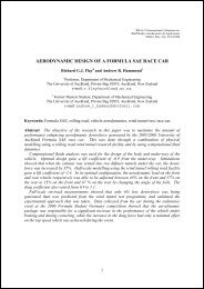
Chapter 1<strong>Topology</strong> <strong>Optimization</strong> of aStructural C-ClipPurposeThis exercise involves performing topology optimization using OptiStruct. The topologyoptimization technique provides us with a new design <strong>and</strong> optimal material distribution.<strong>Topology</strong> optimization is performed on a concept design <strong>and</strong> the resulting design spaceis returned to the designer for suitable modifications. The optimized design in mostcases is lighter <strong>and</strong> performs better than the concept design. The modified design fromthe designer can be further fine-tuned using shape or size optimization.We perform topology optimization on this model to create a new boundary for thisstructure <strong>and</strong> remove any unnecessary material. This optimization normalizes eachelement according to its density <strong>and</strong> lets you remove elements that have low density.This exercise describes the stepsto define topology optimization forthe surface model of a c-clip withshell elements with a singlesubcase (loadstep). The exercisedescribes the steps to perform afinite element mesh; define force,boundary conditions, <strong>and</strong>optimization parameters usingHyperMesh; conduct a linear staticanalysis using OptiStruct; <strong>and</strong>perform its optimization. Theresulting structure is lighter <strong>and</strong>satisfies all constraints.Figure 1-1: <strong>Design</strong> space with conditions <strong>and</strong>design constraintsABOptiStruct 7.0<strong>Concept</strong> <strong>Design</strong> <strong>Using</strong> <strong>Topology</strong> <strong>and</strong> <strong>Topography</strong> <strong>Optimization</strong>Proprietary Information of Altair Engineering, Inc.3
Chapter 1: <strong>Topology</strong> <strong>Optimization</strong> of a Structural C-ClipProblem StatementPerform structural optimization on a structural c-clip (see Figure 1-1) ensuring that aminimum amount of material is used <strong>and</strong> movement at the end nodes of the opening(see A <strong>and</strong> B in Figure 1-1) does not exceed 0.14mm in the y-direction.Objective functionMinimize volumeConstraints 1) Translation in the y-axis for node A < 0.07mm2) Translation in the y-axis at node B > -0.07mm<strong>Design</strong> VariablesElement densities<strong>Optimization</strong> ProcessThe process to complete a topology optimization using OptiStruct is a three-partprocess.• Use HyperMesh to create the appropriate input deck• Run OptiStruct using the created input deck• Examine the resultsThese are the steps the exercise follows.1. Load the geometry into HyperMesh.2. Define the material properties <strong>and</strong> components.3. Generate a finite element mesh.4. Apply loads <strong>and</strong> boundary conditions.5. Create load case.6. Set up optimization problem using HyperMesh.7. Define the design space for optimization.8. Define optimization responses, constraints, <strong>and</strong> objective function.9. Solve topology optimization using OptiStruct to determine the optimal materialdistribution.10. Post-process the results.4<strong>Concept</strong> <strong>Design</strong> <strong>Using</strong> <strong>Topology</strong> <strong>and</strong> <strong>Topography</strong> <strong>Optimization</strong> OptiStruct 7.0Proprietary Information of Altair Engineering, Inc.
Chapter 1: <strong>Topology</strong> <strong>Optimization</strong> of a Structural C-ClipCreate FE ModelStep 1: Load the geometry into HyperMesh1. Launch HyperMesh.2. Go to Geom page <strong>and</strong> click user profile….3. From the pull-down menu, select OptiStruct <strong>and</strong> click OK.4. This sets the HyperMesh environment for the OptiStruct solver.5. From any main page in HyperMesh, select the files panel.6. Select retrieve …, locate the file, cclip.hm, <strong>and</strong> click Open.Sample directory name where input files are located:/altair/tutorials/os/(Note: The instructor will mention the location of the training file for classroominstruction. Otherwise, the files are in the tutorials section of the installation CD).7. Click return to go back to the main page.Step 2: Define the material properties <strong>and</strong> componentsBecause components need to reference a material, create material collectors first.At any time, you can modify the card images <strong>and</strong> materials for collectors from thecollectors panel. For card images, use the card image subpanel. For a differentmaterial, use the update subpanel.1. From any main page of HyperMesh select the collectors panel.2. Click the radio button to the left of create to access the create subpanel.3. To the right of collector type:, click the switch. From the pop-up menu, click mats.4. Click name =. In the text box, type steel.5. Click card image = <strong>and</strong> from the pop up menu select MAT1.6. Click create/edit to load the MAT1 card image for the material steel.7. Click E to select it <strong>and</strong> enter the value of 2e5 <strong>and</strong> in a similar fashion select NU <strong>and</strong>set it to the value of 0.30.8. Click return to go to the collectors panel.9. Change collector type: to comps using the switch.OptiStruct 7.0<strong>Concept</strong> <strong>Design</strong> <strong>Using</strong> <strong>Topology</strong> <strong>and</strong> <strong>Topography</strong> <strong>Optimization</strong>Proprietary Information of Altair Engineering, Inc.5
Chapter 1: <strong>Topology</strong> <strong>Optimization</strong> of a Structural C-Clip10. Click name = <strong>and</strong> type shells.11. Click card image = <strong>and</strong> from the pop up menu select PSHELL.12. Click material =.You will see a list of materials you just created.13. Click steel.14. Click color <strong>and</strong> select yellow (color12).15. Click create/edit to load the PSHELL card image for the component shells.16. Enter the thickness for the shell component by clicking T, clicking in the text box, <strong>and</strong>typing 1.17. Click return to go back to the collectors page.18. Click return to go to a main page.Step 3: Generate a finite element meshUse the automesh module to create a quad dominant mesh. Since the shellscomponent you just created is your current component, any elements you generate areorganized into that component.1. Access the automesh panel. (Select the 2D page, then automesh or press F12).2. Click the check box to the left of reset meshing parameters to:.3. Click element size =, type 2.5, <strong>and</strong> press ENTER to set element size.4. Use the switch under element size to set element type to mixed.5. Select the top half of the surface by clicking any line in that surface.6. Click mesh.The mesh density is displayed on the surface.7. Click mesh again.The automesher should create about 560 shell elements. See the HyperMeshMessage Bar for the message.6<strong>Concept</strong> <strong>Design</strong> <strong>Using</strong> <strong>Topology</strong> <strong>and</strong> <strong>Topography</strong> <strong>Optimization</strong> OptiStruct 7.0Proprietary Information of Altair Engineering, Inc.
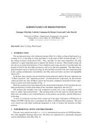
Chapter 1: <strong>Topology</strong> <strong>Optimization</strong> of a Structural C-ClipFigure 1-2: Quad mesh created from automesh panel8. Click return to save the mesh into the shells component.Note the mesh color corresponds to the color selected for the current component.9. Click return to go to the main panel.OptiStruct 7.0<strong>Concept</strong> <strong>Design</strong> <strong>Using</strong> <strong>Topology</strong> <strong>and</strong> <strong>Topography</strong> <strong>Optimization</strong>Proprietary Information of Altair Engineering, Inc.7
Chapter 1: <strong>Topology</strong> <strong>Optimization</strong> of a Structural C-ClipStep 4: Create a mirrored duplicate of the upper surface elements1. Click Tool to select the tool page.2. Select the reflect panel.3. Click the switch under the Reflect heading <strong>and</strong>, from the pop up menu, selectelems.4. Click elems button <strong>and</strong> select displayed from the pop up menu.5. Click elems again <strong>and</strong> from the pop up menu select duplicate, <strong>and</strong> from the nextpop up menu select original comp.6. Click the switch in the center of the page. From the pop up menu, select the normaldirection of the reflection plane (the y-axis in this case).7. Click base <strong>and</strong> select the node as shown in Figure 1-3.The node is needed to reflect the mesh about the y-axis.Figure 1-3: Node to select as base to reflect elements8. Click reflect.Mesh appears in the lower half of the image.9. Click return.10. To refresh the screen, from the permanent menu click p (or press P on thekeyboard).8<strong>Concept</strong> <strong>Design</strong> <strong>Using</strong> <strong>Topology</strong> <strong>and</strong> <strong>Topography</strong> <strong>Optimization</strong> OptiStruct 7.0Proprietary Information of Altair Engineering, Inc.
Chapter 1: <strong>Topology</strong> <strong>Optimization</strong> of a Structural C-ClipStep 5: Equivalencing duplicate nodes between the meshesThe nodes on the edges shared by the two surfaces are defined for each edge. Theyneed to be equivalenced.1. Select the edges panel.2. With the left mouse button, click any of the elements in the figure to select it <strong>and</strong>place its component into the comps buffer.3. Click preview equiv.This highlights the twenty-one nodes defining the seam between the two sets ofelements.4. Click equivalence.The message “21 nodes were equivalenced” appears.5. Click return to go back to the Tool page.Define LoadsStep 1: Create load collectorsCreate two load collectors <strong>and</strong> assign each a color: spc (green) <strong>and</strong> forces (red).Follow these steps for each load collector.1. Go to the BCs page.2. Click collectors.3. Verify the create subpanel is active.4. Click the switch to the right of collector type: <strong>and</strong> select loadcols from the menu.Use steps 4 – 8 to create each load collector <strong>and</strong> assign its name <strong>and</strong> color per thediagram.5. Click name = <strong>and</strong> type in the name of the loadcollector.6. Press enter.7. Click color <strong>and</strong> select assigned color from thepop-up menu.Load Collectors <strong>and</strong>Display ColorLoad Collector Colorspc greenforces red8. Click create.It is not necessary to assign a card image for these load collectors.9. When both collectors are created, click return to go back to the BCs page.OptiStruct 7.0<strong>Concept</strong> <strong>Design</strong> <strong>Using</strong> <strong>Topology</strong> <strong>and</strong> <strong>Topography</strong> <strong>Optimization</strong>Proprietary Information of Altair Engineering, Inc.9
Chapter 1: <strong>Topology</strong> <strong>Optimization</strong> of a Structural C-ClipStep 2: Apply loads <strong>and</strong> boundary conditionsFor the three nodes in Figure 1 - 4 that show constraints, we need to create theseconstraints <strong>and</strong> assign them to the spc load collector. To do that, follow these steps.Figure 1-4: Mesh showing the boundary conditions applied on the c-clip1. From the permanent menu, click global.2. Check the current setting of loadcols =. If it is not spc, click loadcols = <strong>and</strong> selectspc.3. Click return to go to the BCs page.4. Select the constraints panel.5. Left click on the node at the center of the left edge of the design space to select it(see Figure 1-4).Active degrees of freedom contain a check in the box to the left of their label.6. Verify dof1, dof2, <strong>and</strong> dof3 are active.7. De-select dof4, dof5, <strong>and</strong> dof6 by clicking in the check box to remove the check.8. Click create to apply this constraint to the selected node.Note a triangle with a number for each dof selected appears at the node.9. Left click the node at the center of the c-clip curve (see Figure 1-4).10<strong>Concept</strong> <strong>Design</strong> <strong>Using</strong> <strong>Topology</strong> <strong>and</strong> <strong>Topography</strong> <strong>Optimization</strong> OptiStruct 7.0Proprietary Information of Altair Engineering, Inc.
Chapter 1: <strong>Topology</strong> <strong>Optimization</strong> of a Structural C-ClipDegree of freedom (dof)dof1dof2dof3dof4dof5dof6DefinitionTranslation about X-axisTranslation about Y-axisTranslation about Z-axisRotation about X -axisRotation about Y -axisRotation about Z -axis10. Set only dof2.11. Click create.12. Left mouse click on the node at the upper left corner of the c-clip design space (seeFigure 1-4).13. Set only dof3. Unselect any other dof that might be active.14. Click create.Your image should appear as in Fig 1-4.15. Click return.OptiStruct 7.0<strong>Concept</strong> <strong>Design</strong> <strong>Using</strong> <strong>Topology</strong> <strong>and</strong> <strong>Topography</strong> <strong>Optimization</strong>Proprietary Information of Altair Engineering, Inc.11
Chapter 1: <strong>Topology</strong> <strong>Optimization</strong> of a Structural C-ClipStep 3: Apply force boundary conditionsLoad the structure with two opposing forces of 100.0 N at the opposite tips of theopening of the c-clip as shown in Figure 1-5.1. Click global (permanent menu).2. Click loadcol =.3. Select the forces collector.4. Click return.5. From the BCs page, select the forces panel.Figure 1-5: Opposing forces created at the opening of the c-clip6. To create the force at the top of the opening, left mouse click on the node at the topof the opening (A) of the c-clip (see Figure 1-5).7. Click magnitude =, type 100.0 <strong>and</strong> press ENTER.8. Click the switch to the left of N1, N2, N3 <strong>and</strong> from the pop up menu select y-axis.9. Click create.An arrow (pointing up) should appear at the node on the screen.10. To create the force at the bottom of the opening, left mouse click on the node at thebottom of the opening (B) of the c-clip (see Figure 1-5).11. Click magnitude = , type -100.0 <strong>and</strong> press ENTER.12<strong>Concept</strong> <strong>Design</strong> <strong>Using</strong> <strong>Topology</strong> <strong>and</strong> <strong>Topography</strong> <strong>Optimization</strong> OptiStruct 7.0Proprietary Information of Altair Engineering, Inc.
Chapter 1: <strong>Topology</strong> <strong>Optimization</strong> of a Structural C-Clip12. Verify the y-axis is selected (under magnitude =).13. Click create.14. An arrow (pointing down) should appear at the node on the screen.15. To provide a separation between the arrows, select uniform size=, type 7 <strong>and</strong> pressENTER.16. Click return to return to the BCs page.Step 9: Create load caseThe last step in establishing boundary conditions is the creation of an OptiStructsubcase (a load step to HyperMesh).1. From the BCs page, click load steps.2. Click name=, type opposing forces <strong>and</strong> press enter.3. Click loadcols <strong>and</strong> select spc <strong>and</strong> forces from the collector list.4. Click select.5. Click create.6. Click return to go back to the BCs page.Analysis of FE ModelStep 1: Perform analysisWe perform linear static analysis on this cclip before defining the optimization process.An analysis identifies the responses of the structure before optimization. This ensuresconstraints defined for the optimization are reasonable.1. From the BCs page select the OptiStruct panel.This panel exports the deck, runs the analysis/optimization <strong>and</strong> then loads the resultsfiles into HyperMesh after the job is complete.2. Click save as…. <strong>and</strong> enter cclip_analysis.fem as the file name <strong>and</strong> click Save.3. Click the switch below Run Options: <strong>and</strong> select analysis.4. Click optistruct to run the analysis.Running OptiStruct from this panel automatically loads the results file after the job isdone.5. Close the DOS window or shell window <strong>and</strong> click return.OptiStruct 7.0<strong>Concept</strong> <strong>Design</strong> <strong>Using</strong> <strong>Topology</strong> <strong>and</strong> <strong>Topography</strong> <strong>Optimization</strong>Proprietary Information of Altair Engineering, Inc.13
Chapter 1: <strong>Topology</strong> <strong>Optimization</strong> of a Structural C-ClipStep 2: Post-process analysis results1. From the Post page, select the contour panel.2. Click simulation= <strong>and</strong> select opposing forces.3. Click data type= <strong>and</strong> select Displacements.4. Change from total disp to y comp.5. Activate min/max titles <strong>and</strong> info title.6. Click contour.What is the displacement at Nodes A <strong>and</strong> B (upper node <strong>and</strong> lower node,respectively see Figure 1-4)?________________________________________________________7. Click return.<strong>Optimization</strong> SetupStep 1: <strong>Topology</strong> optimizationWe have defined the preliminary finite element model consisting of shell elements,element properties, material properties, <strong>and</strong> loads <strong>and</strong> boundary conditions. Now we willperform topology optimization with the goal of minimizing the amount of material to beused. However, when using less material in the existing mesh with the same loads <strong>and</strong>boundary conditions, we would expect the model to be less stiff <strong>and</strong> deform more than itdid. Therefore, we need to constrain the optimization process with a displacement sothat we achieve a balance between the material to be used <strong>and</strong> the overall stiffness ofthe material.The forces in the structure are applied on the outer nodes of the opening of the clipmaking those two nodes critical locations in the mesh. We applied a displacementconstraint on the end nodes so they would not displace more than 0.07 in the y-axis.Define the design space for topology optimization from the optimization panel inHyperMesh using the topology subpanel. The optimization process is as follows:1. Define the design space for optimization <strong>and</strong> thereby, the design variables.2. Define all responses for the optimization (in this tutorial, the responses would bevolume fraction <strong>and</strong> displacement).3. Define the displacement at the end nodes of the c-clip as constraints.4. Define volume fraction as the objective function..Definingthe same response as the objective function <strong>and</strong> a constraint is notallowed.14<strong>Concept</strong> <strong>Design</strong> <strong>Using</strong> <strong>Topology</strong> <strong>and</strong> <strong>Topography</strong> <strong>Optimization</strong> OptiStruct 7.0Proprietary Information of Altair Engineering, Inc.
Chapter 1: <strong>Topology</strong> <strong>Optimization</strong> of a Structural C-ClipStep 2: Define the topology design variables1. From the BCs page, select optimization.2. Select topology to access the topology optimization subpanel.3. Select create.4. Click comps <strong>and</strong> select shells <strong>and</strong> click select.5. Choose type : to be PSHELL.6. Assign a name of shells in DESVAR= <strong>and</strong> press ENTER.7. Verify base thickness is 0.00.A value of 0.0 implies that the thickness at a specific element can go to zero <strong>and</strong>therefore it becomes a void.8. Click create.9. Click return to go back to optimization panel.Step 3: Define responses for optimizationThe three responses for this problem need to be defined. The first response is thevolume fraction, which forms the objective function, <strong>and</strong> two responses for thedisplacements because the two nodes move in opposite directions.Define volume as a response1. Click Responses.2. In response=, assign the name Vol.3. Change the response type: to volumefrac.4. Verify the toggle below response type: is total.5. Click create.OptiStruct 7.0<strong>Concept</strong> <strong>Design</strong> <strong>Using</strong> <strong>Topology</strong> <strong>and</strong> <strong>Topography</strong> <strong>Optimization</strong>Proprietary Information of Altair Engineering, Inc.15
Chapter 1: <strong>Topology</strong> <strong>Optimization</strong> of a Structural C-ClipDefine displacement as a responseTo create a displacement as a response you need to: supply a meaningful name to theresponse, set the response type to displacement, select the node for the response, <strong>and</strong>select the type of displacement (dof).1. In response=, assign a name upperdis.2. Change the response type: to displacement.3. Click the node labeled A (upper opening of c-clip) in Figure 1-5 to select it.4. Choose the dof2 for the node.5. Click create.6. In response=, assign a name lowerdis.The response type: is still displacement.7. Click the node labeled B (lower opening of the c-clip) in Figure 1-5 to select it.8. Select dof2 <strong>and</strong> create the response.9. Select review to see the list of responses you just created.10. Click return to leave this panel.11. Click return to go back to optimization panel.Define constraintsSet the upper <strong>and</strong> lower bound constraint criteria for this analysis.1. Select dconstraints to access the constraints panel.2. In constraint=, assign a name const1.3. Activate upper bound=.4. In upper bound=, assign a value of 0.07.5. Select response= <strong>and</strong> set it to upperdis.6. Select loadsteps.7. Activate opposing forces.8. Click select.16 <strong>Concept</strong> <strong>Design</strong> <strong>Using</strong> <strong>Topology</strong> <strong>and</strong> <strong>Topography</strong> <strong>Optimization</strong> OptiStruct 7.0Proprietary Information of Altair Engineering, Inc.
Chapter 1: <strong>Topology</strong> <strong>Optimization</strong> of a Structural C-Clip9. Click Create.10. In constraint=, assign a name const2.11. De-activate upper bound=.12. Activate lower bound=.13. In lower bound=, assign a value of –0.07.14. Select response= <strong>and</strong> set it to lowerdis.15. Click loadsteps.16. Select opposing forces.17. Click select.18. Click create.19. Select Review to see a list to the newly created constraints.20. Click return.21. Click return to go back to optimization panel.OptiStruct 7.0<strong>Concept</strong> <strong>Design</strong> <strong>Using</strong> <strong>Topology</strong> <strong>and</strong> <strong>Topography</strong> <strong>Optimization</strong>Proprietary Information of Altair Engineering, Inc.17
Chapter 1: <strong>Topology</strong> <strong>Optimization</strong> of a Structural C-ClipDefine objective function1. Click objective.2. Verify Objective is set to min.3. Click response= <strong>and</strong> select vol.4. Click create.5. Click return twice to exit the <strong>Optimization</strong> panel.Solve the problem1. From the BCs page, select OptiStruct to access the OptiStruct solver.This panel exports the deck, runs the analysis/optimization <strong>and</strong> then loads the resultsfiles into HyperMesh after the job is completed.2. Click save as…., enter cclip_complete.fem as the file name, <strong>and</strong> click Save.This indicates to OptiStruct what file name is to be associated with the variousoutputs it creates <strong>and</strong> where to locate the files. The actual save occurs at thecompletion of the optimization run.3. Click the switch below Run Options: <strong>and</strong> select <strong>Optimization</strong>.4. Click Optistruct to run the optimization.Running OptiStruct from this panel automatically loads the results file after the job isdone. When you click the optistruct button, OptiStruct: writes out the OptiStructinput file, solves the optimization, <strong>and</strong> loads the results into HyperMesh for postprocessing.You no longer need to export the file with the OptiStruct template,manually initiate the solver, <strong>and</strong> import the results file for post-processing.The message “….Processing complete” appears in the window at thecompletion of the OptiStruct job. OptiStruct also reports error messages, if any. Iferror messages appear, open the file cclip_complete.out in a text editor to lookfor details about the error. The cclip_complete.out file is written to the samedirectory as the .fem file.5. Close the DOS window or shell <strong>and</strong> click Return.18<strong>Concept</strong> <strong>Design</strong> <strong>Using</strong> <strong>Topology</strong> <strong>and</strong> <strong>Topography</strong> <strong>Optimization</strong> OptiStruct 7.0Proprietary Information of Altair Engineering, Inc.
Chapter 1: <strong>Topology</strong> <strong>Optimization</strong> of a Structural C-ClipDefault files written to your directory on a successful runcclip_complete.resThe HyperMesh binary results file.cclip_complete.HM.ent.cmfA HyperMesh comm<strong>and</strong> file that organizes elements into entity sets based ontheir density result values (only used with OptiStruct topology optimizationruns).cclip_complete.HM.comp.cmfA HyperMesh comm<strong>and</strong> file that organizes elements into components based ontheir density result values (only used with OptiStruct topology optimizationruns).cclip_complete.outthe OptiStruct output file containing specific information on the file setup, thesetup of your optimization problem, estimate for the amount of RAM <strong>and</strong> diskspace required for the run, information for each optimization iteration, <strong>and</strong>compute time information. Review this file for warnings <strong>and</strong> errors that areflagged from processing the cclip.fem file.cclip_complete.shThe shape file for the final iteration contains the material density, the void sizeparameters, <strong>and</strong> void orientation angle for each element in the analysis. Thisfile may be used to restart a run.cclip_complete.hgdataHyperGraph file containing data for the objective function, percent constraintnotation <strong>and</strong> constraints for each iteration.cclip_complete.ossOSSmooth file with a default density threshold of 0.3. The user may edit theparameters in the file to obtain the desired results.Clip_complete_hist.mvwThis file contains the iteration history of the objective, constraints <strong>and</strong> the designvariables <strong>and</strong> can be used to plot curves in HyperGraph, HyperView, <strong>and</strong>MotionView.Clip_complete.statThis file contains information about the CPU time utilized for the complete run<strong>and</strong> also the break up of the CPU time for reading the input deck, assembly,analysis, convergence etc…OptiStruct 7.0<strong>Concept</strong> <strong>Design</strong> <strong>Using</strong> <strong>Topology</strong> <strong>and</strong> <strong>Topography</strong> <strong>Optimization</strong>Proprietary Information of Altair Engineering, Inc.19
Chapter 1: <strong>Topology</strong> <strong>Optimization</strong> of a Structural C-ClipView ResultsStep 1: Post-process the resultsOptiStruct gives you density information for all iterations. OptiStruct also gives youdisplacement <strong>and</strong> Von Mises Stress results for your linear static analysis in iteration0<strong>and</strong> iteration29. This section describes how to view those results in HyperMesh.View a deformed shapeIt is helpful to first view the deformed shape of your model to determine if the boundaryconditions have been defined correctly <strong>and</strong> also to check if the model is deforming asexpected.1. Select the Post page.2. Select the deformed panel.3. Click simulation =.You will notice that there are many simulations. At the end of the simulation list, yousee opposing forces - ITERATION 0 <strong>and</strong> opposing forces - ITERATION 29.4. Select opposing forces - ITERATION 0.5. Verify the datatype = is pointing to displacements.6. Toggle model units = to scale factor =.7. Set the scale factor to 100.000.8. Click deform to view a deformed plot of your model overlaid on the original,undeformed mesh. (Figure 1-6 shows the plot from a top view).Does the deformed shape look correct for the boundary conditions you applied to themesh?20<strong>Concept</strong> <strong>Design</strong> <strong>Using</strong> <strong>Topology</strong> <strong>and</strong> <strong>Topography</strong> <strong>Optimization</strong> OptiStruct 7.0Proprietary Information of Altair Engineering, Inc.
Chapter 1: <strong>Topology</strong> <strong>Optimization</strong> of a Structural C-ClipFigure 1-6: Deformed plot overlaid on original undeformed mesh. Scale factor is set to100.000. The darker mesh is the deformed plot <strong>and</strong> the lighter mesh is the original location.9. Click return.View a transient animation of density resultsThis step views how the material distributes during the optimization.1. From the permanent menu select the options panel.2. Select the graphics subpanel.3. Toggle the graphics engine mode to st<strong>and</strong>ard.4. Click return.5. From the Post page in HyperMesh, select the transient panel.6. Set start with = DESIGN-ITER0.7. Set end with = DESIGN–ITER29, the last iteration.8. Set data type = to Element Density.9. Click transient.OptiStruct 7.0<strong>Concept</strong> <strong>Design</strong> <strong>Using</strong> <strong>Topology</strong> <strong>and</strong> <strong>Topography</strong> <strong>Optimization</strong>Proprietary Information of Altair Engineering, Inc.21
Chapter 1: <strong>Topology</strong> <strong>Optimization</strong> of a Structural C-Clip10. Set the following options located on the left side of the animation panel.modecolorlightsmeshhidden linecontoursmoothon11. Use the slower button to slow down the animation if the frames animate too quickly.12. Click exit when you are finished viewing the animation.13. Click return.View a static contour plotThis plot assigns density to all the elements in the model.1. From the Post page in HyperMesh, select the contour panel.2. Set simulation = to DESIGN–ITER29.3. Click data type = <strong>and</strong> select Element Density.4. Click assign to see the element densities of each element at the end of optimization.The regions with high element densities indicate the areas where material is needed<strong>and</strong> the regions with low element densities are areas with scope for mass reduction.5. Click return.View an isosurface plotThis plot provides the information about the element density. Isosurface retains all theelements at <strong>and</strong> above a certain density threshold. Pick the density threshold providingthe structure that suits your needs.1. From the permanent menu, select the options panel.2. Select the graphics subpanel.3. Toggle the graphics engine mode to per (performance).4. Click return.5. From the Post page in HyperMesh, select the contour panel.6. Set your simulation to DESIGN–ITER29.7. Click data type = <strong>and</strong> select Element Density.8. Click the radio button to the left of isosurface to select the subpanel.22<strong>Concept</strong> <strong>Design</strong> <strong>Using</strong> <strong>Topology</strong> <strong>and</strong> <strong>Topography</strong> <strong>Optimization</strong> OptiStruct 7.0Proprietary Information of Altair Engineering, Inc.
Chapter 1: <strong>Topology</strong> <strong>Optimization</strong> of a Structural C-Clip9. Activate show.10. Toggle the mode from legend based to value based.11. Set the iso surface = field to 0.300.12. Activate include faces above.13. Click contour.Figure 1-7: Isosurface plot of an optimal layout of the designable material14. On the triangle shown in the legend (currently pointing to a value representing 0.300for your density), click <strong>and</strong> hold the left mouse button then scroll up <strong>and</strong> down tochange the threshold surface. You will see the isosurface in the graphics windowupdate interactively when you scroll to a new value. Use this tool to get a better lookat the material layout <strong>and</strong> the load paths from OptiStruct.OptiStruct 7.0<strong>Concept</strong> <strong>Design</strong> <strong>Using</strong> <strong>Topology</strong> <strong>and</strong> <strong>Topography</strong> <strong>Optimization</strong>Proprietary Information of Altair Engineering, Inc.23
Chapter 1: <strong>Topology</strong> <strong>Optimization</strong> of a Structural C-ClipReview1. Have most of your elements converged to a density of 1 or 0?If there are many elements with intermediate densities, you may need to adjust thediscrete parameter. The DISCRETE parameter (set in the opti cntl panel) can beused to push elements with intermediate densities towards 1 or 0 so that a morediscrete structure is given.2. Is the max = field showing 1.0e+00?In this case, it is.If it is not, your optimization has not progressed far enough. Allow more iterations<strong>and</strong>/or decrease the OBJTOL parameter (set in the opti cntl panel).ConclusionThe exercises in this tutorial covered:• Creating a finite element mesh using HyperMesh.• Creating loads <strong>and</strong> boundary conditions.• Performing linear static analysis <strong>and</strong> topology optimization.• Post-processing topology results using isosurfaces in HyperMesh.24<strong>Concept</strong> <strong>Design</strong> <strong>Using</strong> <strong>Topology</strong> <strong>and</strong> <strong>Topography</strong> <strong>Optimization</strong> OptiStruct 7.0Proprietary Information of Altair Engineering, Inc.
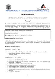
Chapter 2<strong>Topology</strong> <strong>Optimization</strong> of anAutomotive Control ArmPurposeThis exercise involves performing topology optimization using OptiStruct. <strong>Topology</strong>optimization is a technique that provides a new design boundary <strong>and</strong> optimal materialdistribution. <strong>Topology</strong> optimization is performed on a concept design <strong>and</strong> the resultingdesign space is returned to the designer for suitable modifications. The optimized designwill always be lighter <strong>and</strong> usually stiffer than the concept design. The modified designfrom the designer can then be further fine-tuned using shape or size optimization.This exercise describes the steps involved in defining a topology optimization for anautomotive control arm modeled with solid elements <strong>and</strong> with three subcases(loadsteps). The exercise describes the steps to define force, boundary conditions, <strong>and</strong>optimization parameters using HyperMesh.The optimization is carried out with constraints for three different subcases. The resultingstructure is lighter <strong>and</strong> satisfies constraints for all subcases.Problem statementPerform topology optimization on an automotive control arm. The optimization problemfor this exercise is:Objective:minimize volumeConstraints: resultant displacement at node id 2699 induced by subcase 1 < 0.05.<strong>Design</strong> variables:resultant displacement at node id 2699 induced by subcase 2 < 0.02.resultant displacement at node id 2699 induced by subcase 3 < 0.04.element densityOptiStruct 7.0<strong>Concept</strong> <strong>Design</strong> <strong>Using</strong> <strong>Topology</strong> <strong>and</strong> <strong>Topography</strong> <strong>Optimization</strong>Proprietary Information of Altair Engineering, Inc.25
Chapter 2: <strong>Topology</strong> <strong>Optimization</strong> of an Automotive Control ArmFigure 2-1: Finite element mesh containing designable <strong>and</strong> non-designable material<strong>Optimization</strong> ProcessThe process to complete a topology optimization using OptiStruct is a three-partprocess.• Use HyperMesh to create the appropriate input deck.• Run OptiStruct using the created input deck.• Examine the results.This tutorial will follow the steps outlined below:1. Load the model into HyperMesh.2. Define material properties <strong>and</strong> assign materials to the components.3. Apply load <strong>and</strong> boundary conditions.4. Setup the optimization problem using HyperMesh.5. Define the design space for optimization.6. Define optimization responses, constraints, <strong>and</strong> objective function.7. Solve topology optimization using OptiStruct to determine the optimal materialdistribution.8. Post-process the results.26<strong>Concept</strong> <strong>Design</strong> <strong>Using</strong> <strong>Topology</strong> <strong>and</strong> <strong>Topography</strong> <strong>Optimization</strong> OptiStruct 7.0Proprietary Information of Altair Engineering, Inc.
Chapter 2: <strong>Topology</strong> <strong>Optimization</strong> of an Automotive Control ArmLoad the ModelStep 1: Set up the FEA model in HyperMesh1. Delete the current model by pressing F2 to access the delete panel <strong>and</strong> selectingdelete model.2. From any main page in HyperMesh, select the files panel.3. Select hm file.4. Click retrieve …, select carm.hm, <strong>and</strong> click Open.5. Click return.6. From the Geom page, select user prof….7. Select optistruct from the list <strong>and</strong> click OK.This sets the HyperMesh environment for the OptiStruct solver .Step 2: Set up material propertiesThe components for this exercise have already been created. The next step is to createthe material collectors <strong>and</strong> assign to each component the appropriate material.Create a material called steel1. From the Geom page select the collectors panel.2. Select the create subpanel.3. Specify the collector type to be mats by clicking the switch to the right of collectortype: <strong>and</strong> from the pop up menu choose mats.4. Select name =, type steel in the text box, <strong>and</strong> press ENTER.5. Select card image = <strong>and</strong>, from the pop up menu, choose MAT1.6. Click create/edit to load the MAT1 card image for the new material, steel.7. Set the values for E to 2E5 <strong>and</strong> NU to 0.300.To establish values in these fields: Select the field name, click in the text box, type ina value, <strong>and</strong> press ENTER..Sincethis problem is a linear static analysis with volume as a response, you donot need to define a density value. Density values are required for a normalmodes analysis or if mass is used as a response.8. Click return.OptiStruct 7.0<strong>Concept</strong> <strong>Design</strong> <strong>Using</strong> <strong>Topology</strong> <strong>and</strong> <strong>Topography</strong> <strong>Optimization</strong>Proprietary Information of Altair Engineering, Inc.27
Chapter 2: <strong>Topology</strong> <strong>Optimization</strong> of an Automotive Control ArmAssign the material to the components1. Remain in the collectors panel, <strong>and</strong> select the update subpanel.2. Change the collector type to comps.3. Click the yellow comps button.4. Activate components, design <strong>and</strong> non-design (click the box on the left of each).5. Click select.6. Click material= <strong>and</strong> select steel.7. Click the green update button.8. Activate material id.9. Click update.The MID fields for both components should now be set to 1 since only one material isdefined. The following steps allow you to verify the card image for each componentto ensure the MID fields are updated.10. Select the card image subpanel.11. Click name = twice <strong>and</strong> select nondesign.12. Select card image = <strong>and</strong> choose PSOLID.13. Click load/edit.14. Verify MID is 1.15. Click return.16. Repeat 10 through 15 for the design component.17. Click return.Step 3: Apply boundary conditions <strong>and</strong> loadsCreate the load collectorsThis problem requires four load collectors, one for boundary conditions <strong>and</strong> three forforces in the x, y, <strong>and</strong> z-axis at node 2699. To accomplish this, give each collector ameaningful name, assign it a color, then create it. The following steps take you throughthis process for all four collectors.1. On the collectors panel, select the create subpanel.2. Set the collector type: to loadcols (click on the switch to the right of collector type:<strong>and</strong> choose loadcols from the pop up menu).3. Click name = <strong>and</strong> type spc.28<strong>Concept</strong> <strong>Design</strong> <strong>Using</strong> <strong>Topology</strong> <strong>and</strong> <strong>Topography</strong> <strong>Optimization</strong> OptiStruct 7.0Proprietary Information of Altair Engineering, Inc.
Chapter 2: <strong>Topology</strong> <strong>Optimization</strong> of an Automotive Control Arm4. Click color <strong>and</strong> select green (color 10).5. Click create.6. Click name= <strong>and</strong> type brake.7. Click color <strong>and</strong> select yellow (color 12).8. Click create.9. Click name= <strong>and</strong> type, corner.10. Click color <strong>and</strong> select orange (color 13).11. Click create.12. Click name = <strong>and</strong> type, pothole.13. Click color <strong>and</strong> select red (color 15).14. Click create.15. To review all of the collectors, click name = twice <strong>and</strong> read through the list. Thenclick return to bring up the collectors panel.16. Click return to go back to the main screen.Apply constraints to the modelThe model needs to be constrained using single point constraints at the two bushinglocations. Apply constraints dof1, dof2 <strong>and</strong> dof3 at one end of the bushing <strong>and</strong> dof2,dof3 at the other end. Apply constraint dof3 on node 3239.1. Click global in the permanent menu, then click loadcol=.2. Select spc from the list.3. Click return.4. From the BCs page, select the constraints panel.5. Select the foreground node at one end of the bushing (see Figure 2-2) <strong>and</strong> constraindof1, dof2 <strong>and</strong> dof3.DOFs Definition1 Translation on x-axis.2 Translation on y-axis.3 Translation on z-axis.4 Rotation on x-axis.5 Rotation on y-axis.6 Rotation on z-axis.Make sure dofs 1,2 <strong>and</strong> 3 have been checked.OptiStruct 7.0<strong>Concept</strong> <strong>Design</strong> <strong>Using</strong> <strong>Topology</strong> <strong>and</strong> <strong>Topography</strong> <strong>Optimization</strong>Proprietary Information of Altair Engineering, Inc.29
Chapter 2: <strong>Topology</strong> <strong>Optimization</strong> of an Automotive Control Arm6. Select create to apply these constraints to the selected node.Figure 2-2: Constraining dof1, dof2 <strong>and</strong> dof3 at one end of the bushing7. Select the background node at the other end of the bushing (see Figure 2-3) <strong>and</strong>constrain dof2 <strong>and</strong> dof3.Figure 2-3: Constraining dof2 <strong>and</strong> dof3 at the other end of the bushing30<strong>Concept</strong> <strong>Design</strong> <strong>Using</strong> <strong>Topology</strong> <strong>and</strong> <strong>Topography</strong> <strong>Optimization</strong> OptiStruct 7.0Proprietary Information of Altair Engineering, Inc.
Chapter 2: <strong>Topology</strong> <strong>Optimization</strong> of an Automotive Control Arm8. Make sure the check boxes to the left of dofs 2 <strong>and</strong> 3 have checks.9. Select create to apply these constraints to the selected node.10. From the permanent menu, click f to fit the model to the screen.11. Click nodes, then select by id.12. Type 3239 <strong>and</strong> press ENTER to select node ID 3239.Move mouse off pop-up menu to close the menu. See Figure 2-4.Figure 2-4: Constraining dof3 on node id 323913. Select dof3 to activate it.14. Select create to apply the constraint to the selected node.15. Click return to bring up the BCs menu page in HyperMesh.OptiStruct 7.0<strong>Concept</strong> <strong>Design</strong> <strong>Using</strong> <strong>Topology</strong> <strong>and</strong> <strong>Topography</strong> <strong>Optimization</strong>Proprietary Information of Altair Engineering, Inc.31
Chapter 2: <strong>Topology</strong> <strong>Optimization</strong> of an Automotive Control ArmStep 4: Apply forces to the modelAt node 2699, load the structure with three separate forces in the x, y, <strong>and</strong> z directionsorganized into the three load collectors brake, corner, <strong>and</strong> pothole.Use the following table values to set the forces. Use the instructions below for eachforce.Node Id Collector Magnitude Axis2699 brake 1000 x-axis2699 corner 1000 y-axis2699 pothole 1000 z-axisCreate forces by node1. From the BCs page, access the forces panel.2. Select the create subpanel.3. Click global in the permanent menu.4. Click loadcol = to access the list of collectors.5. Select the appropriate collector from the table provided.6. Click return to go back to the forces panel.7. Click the yellow nodes button.8. Choose by id.9. Enter the id number (from the table provided) <strong>and</strong> press ENTER <strong>and</strong> move themouse to release the pop up menu.10. Click magnitude =, type in the value from the table, <strong>and</strong> press ENTER.11. Set the vector definition switch below magnitude = to the appropriate axis accordingto the table.12. Click create.13. Repeat Steps 3 -13 for the remaining forces.14. After you have created all three forces, click return to go back to the BCs panel.Your forces should appear as in Figure 2-5.32<strong>Concept</strong> <strong>Design</strong> <strong>Using</strong> <strong>Topology</strong> <strong>and</strong> <strong>Topography</strong> <strong>Optimization</strong> OptiStruct 7.0Proprietary Information of Altair Engineering, Inc.
Chapter 2: <strong>Topology</strong> <strong>Optimization</strong> of an Automotive Control ArmFigure 2-5: Three separate forces in load collectors brake, corner <strong>and</strong> potholeOptiStruct 7.0<strong>Concept</strong> <strong>Design</strong> <strong>Using</strong> <strong>Topology</strong> <strong>and</strong> <strong>Topography</strong> <strong>Optimization</strong>Proprietary Information of Altair Engineering, Inc.33
Chapter 2: <strong>Topology</strong> <strong>Optimization</strong> of an Automotive Control ArmSet up loadstepsThe last step in setting up the boundary conditions is to create OptiStruct subcases(loadsteps in HyperMesh). The procedure is to name the loadstep <strong>and</strong> associate theappropriate load collectors to the loadstep.1. From the BCs page of HyperMesh, access the load steps panel.2. Click name =, type brake, <strong>and</strong> press ENTER.3. Select loadcols <strong>and</strong> activate spc <strong>and</strong> brake from the collector list.4. Click select.5. Click create.6. Click name =, type corner, <strong>and</strong> press ENTER.7. Select loadcols <strong>and</strong> activate spc <strong>and</strong> corner from the collector list.8. Click select <strong>and</strong> then click create.9. Click name =, type pothole, <strong>and</strong> press ENTER.10. Select loadcols <strong>and</strong> activate spc <strong>and</strong> pothole from the collector list.11. Click select.12. Click create.13. Verify the creation of all three loadsteps by clicking review.14. Click return to go back to the load steps panel.15. Click return to go back to the BCs page.34<strong>Concept</strong> <strong>Design</strong> <strong>Using</strong> <strong>Topology</strong> <strong>and</strong> <strong>Topography</strong> <strong>Optimization</strong> OptiStruct 7.0Proprietary Information of Altair Engineering, Inc.
Chapter 2: <strong>Topology</strong> <strong>Optimization</strong> of an Automotive Control ArmPrepare for <strong>Optimization</strong>Step 1: Set up topology optimizationDefine topology design space for solid elementsThese steps define the whole component of design as a designable region. Thecomponent non-design is not affected when optimization is performed.1. From the BCs page, select the optimization panel.2. Click topology.3. Select the create subpanel.4. Select comps.5. Activate design.6. Click Select.7. Select the component type by selecting the type: switch <strong>and</strong> choosing PSOLID fromthe popup menu.8. To desvar = assign the name solids.9. Click create.10. Click return to go back to the optimization set up panel.Define responses for optimizationThe objective of this exercise is to remove material from the control arm. Three differentforces are applied at one end of the control arm <strong>and</strong> that node has the maximumdisplacement in the structure. Therefore define the optimization deck with the objectivefunction of minimizing the volume <strong>and</strong> constraints as the displacement of node 2699 atthe application of the forces..Sinceall three load cases use the same node <strong>and</strong> direction of displacement,we need to define only one response for the displacement.1. From the optimization panel, select the responses panel.2. For response =, assign the name vol.3. Set the response type: to volumefrac by clicking the switch <strong>and</strong> selectingvolumefrac from the pop up menu.4. Click create.OptiStruct 7.0<strong>Concept</strong> <strong>Design</strong> <strong>Using</strong> <strong>Topology</strong> <strong>and</strong> <strong>Topography</strong> <strong>Optimization</strong>Proprietary Information of Altair Engineering, Inc.35
Chapter 2: <strong>Topology</strong> <strong>Optimization</strong> of an Automotive Control Arm5. For response =, assign the name disp.6. As the response type:, select displacement.7. Click nodes <strong>and</strong> select by id <strong>and</strong> enter the node 2699.8. Below the nodes button activate total disp as the direction of displacement.9. Click create.10. Click return to go back to the optimization set up panel.Figure 2-6: Displacement response defined on node 2699Define constraints for optimization1. From the optimization set up panel, select the dconstraints subpanel.2. To constraint =, assign the name brake.3. Activate upper bound <strong>and</strong> assign the value 0.05.4. Click response =.5. Select disp.6. Click loadsteps button.36<strong>Concept</strong> <strong>Design</strong> <strong>Using</strong> <strong>Topology</strong> <strong>and</strong> <strong>Topography</strong> <strong>Optimization</strong> OptiStruct 7.0Proprietary Information of Altair Engineering, Inc.
Chapter 2: <strong>Topology</strong> <strong>Optimization</strong> of an Automotive Control Arm7. Activate brake.8. Click select.9. Click create.10. At constraint=, assign the name corner.11. At upper bound =, assign the value 0.02.12. Click loadsteps.13. Activate corner.14. Click select.15. Click create.16. At constraint =, assign the name pothole.17. At upper bound =, assign the value 0.04.18. Click loadsteps.19. Activate pothole.20. Click select.21. Click create.22. You can use the review button to see the constraints you created.23. Click return to go back to the optimization set up panel.Define objective function1. From the optimization panel, select the objective subpanel.2. Verify the switch is set to min.3. Click response = <strong>and</strong> select vol.4. Click create.5. Click return.6. Click return again to return to the BCs page.OptiStruct 7.0<strong>Concept</strong> <strong>Design</strong> <strong>Using</strong> <strong>Topology</strong> <strong>and</strong> <strong>Topography</strong> <strong>Optimization</strong>Proprietary Information of Altair Engineering, Inc.37
Chapter 2: <strong>Topology</strong> <strong>Optimization</strong> of an Automotive Control ArmStep 2: Set up a check run for OptiStructDuring the check run, OptiStruct checks the syntax of the input deck, calculates arecommended amount of RAM, <strong>and</strong> estimates the required disk space for the model.OptiStruct also scans the input deck verifying the parameters required to run theanalysis <strong>and</strong> optimization.1. From the BCs page select OptiStruct.From this panel you can export the deck, run the analysis/optimization, <strong>and</strong> thenafter the job completes load the results files into HyperMesh. A check run can alsobe performed from this panel.2. Click save as…, enter carm_check.fem as the file name, <strong>and</strong> click Save.3. Click the switch below Run Options: <strong>and</strong> select Check.4. Click optistruct to run the check run.The check run for this model should take approximately 5 to 10 seconds ofprocessing time.Once the processing completes, view the file carm_check.out at the UNIX promptor through a Windows utility. The OptiStruct output file contains specific informationon the file setup, the setup of your optimization problem, an estimate for the amountof RAM <strong>and</strong> disk space required for the run, information for each optimizationiteration, <strong>and</strong> compute time information. Review this file for possible warnings <strong>and</strong>errors that are flagged from processing the carm_check.fem file.5. Close the DOS window or shell <strong>and</strong> click return.38<strong>Concept</strong> <strong>Design</strong> <strong>Using</strong> <strong>Topology</strong> <strong>and</strong> <strong>Topography</strong> <strong>Optimization</strong> OptiStruct 7.0Proprietary Information of Altair Engineering, Inc.
Chapter 2: <strong>Topology</strong> <strong>Optimization</strong> of an Automotive Control ArmCheck for correct setup of your optimization problemReview your report <strong>and</strong> check the objective function <strong>and</strong> constraints (Figure 2-7).Figure 2-7: Portion of carm_check.out showing the optimization problem setup1. What is the recommended amount of RAM for an In-Core solution?2. Do you have enough disk space to run the optimization?3. Close carm_check.out.OptiStruct 7.0<strong>Concept</strong> <strong>Design</strong> <strong>Using</strong> <strong>Topology</strong> <strong>and</strong> <strong>Topography</strong> <strong>Optimization</strong>Proprietary Information of Altair Engineering, Inc.39
Chapter 2: <strong>Topology</strong> <strong>Optimization</strong> of an Automotive Control ArmRequest both H3D (*.h3d) <strong>and</strong> HyperMesh binary result output (*.res)The FORMAT control card allows you to create multiple result files. An H3D file is acompressed result format used for post-processing in HyperView <strong>and</strong> HyperView Player.1. From the BCs page, select the control cards panel.2. Select the FORMAT subpanel.3. Set number_of_formats = to 2.In the area above the card image, a second FORMAT card appears. The defaultvalue is HM.4. Select the top HM button <strong>and</strong> change it to H3D.The lower HM button signifies the production of a .res file.5. Click return.6. Notice the Format button is green, indicating it is active.7. Click return to go back to the BCs page.Run the optimization1. From the BCs page <strong>and</strong> select OptiStruct to go the optistruct panel.This panel exports the deck, runs the analysis/optimization, <strong>and</strong> then loads theresults files into HyperMesh once the job is complete.2. Click save as…, enter carm_complete.fem as the file name, <strong>and</strong> click Save.3. Click the switch below Run Options: <strong>and</strong> select <strong>Optimization</strong>.4. Click optistruct to run the optimization.Running OptiStruct from this panel causes the results file to load automatically whenthe job finishes.The full topology optimization should take approximately 10 to 15 minutes for 25iterations (about 25 seconds for each finite element analysis). Actual performancedepends on your processor, available RAM, <strong>and</strong> time required for systemcommunications.After processing is complete, you should see a new file carm_complete.out in thedirectory from where HyperMesh was invoked. The file is a good place to look forerror messages to help you debug your input deck for any errors.5. Close the DOS window or shell.6. Click return.40<strong>Concept</strong> <strong>Design</strong> <strong>Using</strong> <strong>Topology</strong> <strong>and</strong> <strong>Topography</strong> <strong>Optimization</strong> OptiStruct 7.0Proprietary Information of Altair Engineering, Inc.
Chapter 2: <strong>Topology</strong> <strong>Optimization</strong> of an Automotive Control ArmDefault files written to your directory on a successful runcarm_complete.resThe HyperMesh binary results file.carm_complete.HM.ent.cmfA HyperMesh comm<strong>and</strong> file used to organize elements into entity sets basedon their density result values (only used with OptiStruct topology optimizationruns).carm_complete.HM.comp.cmfA HyperMesh comm<strong>and</strong> file used to organize elements into components basedon their density result values (only used with OptiStruct topology optimizationruns).carm_complete.outThe OptiStruct output file containing specific information on the file setup, thesetup of your optimization problem, estimate for the amount of RAM <strong>and</strong> diskspace required for the run, information for each optimization iteration, <strong>and</strong>compute time information. Review this file for warnings <strong>and</strong> errors that areflagged from processing the carm_complete.fem file.carm_complete.hgdataHyperGraph file containing data for the objective function, percent constraintviolations <strong>and</strong> constraint for each iteration.carm_complete.ossOSSmooth file with a default density threshold of 0.3. The user may edit theparameters in the file to obtain the desired results.carm_complete.shShape file for the final iteration. It contains the material density, void sizeparameters, <strong>and</strong> void orientation angle for each element in the analysis. The.sh file may be used to restart a run <strong>and</strong>, if necessary, run OSSmooth files fortopology optimization.Carm_complete_hist.mvwThis file contains the iteration history of the objective, constraints <strong>and</strong> thedesign variables <strong>and</strong> can be used to plot curves inHyperGraph/HyperView/MotionViewCarm_complete.statThis file contains information about the CPU time utilized for the complete run<strong>and</strong> also the break up of the CPU time for reading the input deck, assembly,analysis, convergence etc…OptiStruct 7.0<strong>Concept</strong> <strong>Design</strong> <strong>Using</strong> <strong>Topology</strong> <strong>and</strong> <strong>Topography</strong> <strong>Optimization</strong>Proprietary Information of Altair Engineering, Inc.41
Chapter 2: <strong>Topology</strong> <strong>Optimization</strong> of an Automotive Control ArmPost-processOptiStruct provides density information for all iterations. OptiStruct also providesdisplacement <strong>and</strong> von Mises Stress results for linear static analysis in the first <strong>and</strong> lastiteration. This section describes how to view those results using HyperMesh.Step 1: View deformed resultsIt is helpful to first view the deformed shape of your model to determine if the boundaryconditions have been defined correctly <strong>and</strong> also to check if the model is deforming asexpected.1. From the Post page, select the deformed panel.2. Click simulation =.You will notice that there are many simulations. At the end of the simulation list, youwill see brake - ITER0, brake – ITER21, corner - ITER0, corner - ITER21, pothole -ITER0 <strong>and</strong> pothole - ITER21.3. Select brake – ITER21.4. Set data type to displacements.5. Toggle model units= to scale factor=.6. Set your scale factor to 10.00.7. Click linear to view a deformed animation for brake – ITER21.In what direction is the load applied for the subcase named brake?______________________________________________Which nodes have degrees of freedom constrained?______________________________________________Does the deformed shape look correct for the boundary conditions you applied to themesh? ______________________________________________8. View the linear animation for the 2 nd <strong>and</strong> 3 rd subcases (iteration 21).Second subcase named corner:In what direction is the load applied for the subcase named corner?______________________________________________Which nodes have degrees of freedom constrained?42______________________________________________<strong>Concept</strong> <strong>Design</strong> <strong>Using</strong> <strong>Topology</strong> <strong>and</strong> <strong>Topography</strong> <strong>Optimization</strong> OptiStruct 7.0Proprietary Information of Altair Engineering, Inc.
Chapter 2: <strong>Topology</strong> <strong>Optimization</strong> of an Automotive Control ArmDoes the deformed shape look correct for the boundary conditions you applied to themesh? ______________________________________________Third subcase named pothole:In what direction is the load applied for the subcase named pothole?______________________________________________Which nodes have degrees of freedom constrained?______________________________________________Does the deformed shape look correct for the boundary conditions you applied to themesh? ______________________________________________9. Click exit.10. Click return.Step 2: View a static contour plotYou may wish to mask your rigid elements before using the contour panel. Densityresults are not given for 1D elements.1. Press F5 (function key on your keyboard) to access the mask panel.2. Click the yellow elems button.3. Select by config.4. Click config =.5. Select rigid.6. Click select entities.7. Click mask.8. Click return.9. From the Post page, access the contour panel.10. Set simulation = to DESIGN - ITER21.11. Click data type = <strong>and</strong> select Element Density.OptiStruct 7.0<strong>Concept</strong> <strong>Design</strong> <strong>Using</strong> <strong>Topology</strong> <strong>and</strong> <strong>Topography</strong> <strong>Optimization</strong>Proprietary Information of Altair Engineering, Inc.43
Chapter 2: <strong>Topology</strong> <strong>Optimization</strong> of an Automotive Control Arm12. Click assign.Have most of your elements converged to a density close to 1 or 0?If there are many elements with intermediate densities, you may need to adjust thediscrete parameter. The DISCRETE parameter (set in the opti control panel) canbe used to push elements with intermediate densities towards 1 or 0 so that a morediscrete structure is given.In this model, refining the mesh should provide a more discrete solution; however, forthe sake of this tutorial, the current mesh <strong>and</strong> results will be sufficient.Regions that need reinforcement will tend towards a density of 1.0. Areas that donot need reinforcement will tend towards a density of 0.0.Is the max= field showing 1.0e+00?In this case, it is.If it is not, your optimization has not progressed far enough. Allow more iterations<strong>and</strong>/or decrease the OBJTOL parameter (set in the control cards panel).If adjusting your discrete parameter, refining the mesh, <strong>and</strong>/or decreasing theobjective tolerance does not yield a more discrete solution (none of the elementsprogress to a density value of 1.0), you may wish to review the setup of theoptimization problem. Perhaps some of the defined constraints are not attainable forthe given objective function (or visa-versa).44<strong>Concept</strong> <strong>Design</strong> <strong>Using</strong> <strong>Topology</strong> <strong>and</strong> <strong>Topography</strong> <strong>Optimization</strong> OptiStruct 7.0Proprietary Information of Altair Engineering, Inc.
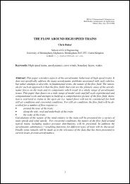
Chapter 2: <strong>Topology</strong> <strong>Optimization</strong> of an Automotive Control ArmStep 3: View an isosurface plot1. Access the options panel in the permanent menu.2. Select the graphics subpanel.3. Toggle the graphics engine mode to performance.4. Click return.5. Select the contour panel from the Post page in HyperMesh.6. Set your simulation to DESIGN–ITER 21.7. Click data type = <strong>and</strong> select Element Density.8. Select the isosurface subpanel.9. Activate show.10. Toggle the mode from legend based to value based.11. Set the iso surface= 0.150.12. Activate include faces above.13. Click assign.Figure 2-8: Isosurface plot of an optimal layout of the designable material14. Use the isosurface post-processing feature in HyperMesh for viewing your densityresults from OptiStruct.Click <strong>and</strong> hold the left mouse button on the triangle shown in the legend (currentlypointing to a value representing 0.150 for your density), then scroll up <strong>and</strong> down tochange the threshold surface. You will see the isosurface in the graphics windowinteractively update when you scroll to a new value. Use this tool to get a better lookat the material layout <strong>and</strong> the load paths from OptiStruct.15. Click return.OptiStruct 7.0<strong>Concept</strong> <strong>Design</strong> <strong>Using</strong> <strong>Topology</strong> <strong>and</strong> <strong>Topography</strong> <strong>Optimization</strong>Proprietary Information of Altair Engineering, Inc.45
Chapter 2: <strong>Topology</strong> <strong>Optimization</strong> of an Automotive Control ArmStep 4: View result using HyperView Player1. Go to the current working directory <strong>and</strong> locate the file carm_complete.html.2. Right-click carm_complete.html <strong>and</strong> select Open.The system web browser application (Netscape or Internet Explorer, for example)initializes displaying the OptiStruct report in HTML format.3. Review the HTML report.4. From the results summary section of the report, select the blue Click here hyperlink.This displays the OptiStruct H3d in HyperView Player. You can select the simulationtype, result type <strong>and</strong> simulation id to review results.5. Exit the web browser application.Step 5: View results using comm<strong>and</strong> filesOptiStruct creates two HyperMesh comm<strong>and</strong> files carm_complete.HM.ent.cmf <strong>and</strong>carm_complete.HM.comp.cmf that could be used to organize the elements into entitysets <strong>and</strong> components based on their density results values.1. From any page in HyperMesh select the files panel.2. Select the comm<strong>and</strong> subpanel.3. Select the file carm_complete.hm.ent.cmf.4. Click execute.5. Repeat steps 3 <strong>and</strong> 4 for file carm_complete.hm.comp.cmf.6. Click return.7. Press F5 to activate the mask panel.8. Click elems <strong>and</strong> select by sets.9. There are 10 different entity sets from 0.0-0.1, 0.1-0.2, 0.2-0.3 <strong>and</strong> so on.10. Select the entity sets 0.0-0.1 <strong>and</strong> 0.1-0.2 <strong>and</strong> click select.11. Click mask.Only elements with densities above 0.2 are displayed. The elements with densitylevels greater than 0.2 may be masked also using the masking panel <strong>and</strong> theappropriate entity sets.12. Click Unmask all <strong>and</strong> click return.13. The elements with different density levels grouped into different components may beobserved by clicking disp on the permanent menu <strong>and</strong> turning off the components0.0-0.1, 0.1-0.2 by right clicking the check box.14. Click return.46<strong>Concept</strong> <strong>Design</strong> <strong>Using</strong> <strong>Topology</strong> <strong>and</strong> <strong>Topography</strong> <strong>Optimization</strong> OptiStruct 7.0Proprietary Information of Altair Engineering, Inc.
Chapter 2: <strong>Topology</strong> <strong>Optimization</strong> of an Automotive Control ArmStep 6: Running OSSmoothThe isosurface plot provides a graphic image of the material with different density levels.Once you decide on the density level to be used for the optimized model, the geometrysurface of the desired optimized density can be obtained by running OSSmooth. Theexecution of OSSmooth results in creation of an iso-density surface in the format ofNASTRAN triangular elements, surface patches in IGES format, STL format, MotionViewtriangles, <strong>and</strong> H3D format. It requires both .fem <strong>and</strong> .sh files from the optimization run.1. From the post page, click OSSmooth.2. Click browse…, <strong>and</strong> select the file carm_complete.fem.3. Change the output code to IGES.4. Change the density threshold to 0.15.5. Verify surface reduction is on.6. Set surface code to laplacian smoothing.7. Click OSSmooth.8. The message “carm_complete.oss file exists. Overwrite? (y/n)” appears, click Yes.OSSmooth reads in geometry automatically. OSSmooth starts <strong>and</strong> after the programterminates, close the OSSmooth comm<strong>and</strong> window (MS-DOS for Windows <strong>and</strong> kshfor UNIX). The iges file is automatically imported.9. Click disp in permanent menu.10. De-activate comps nondesign <strong>and</strong> design (use a right-click).11. Click return.Review1. Has the objective function been satisfied?2. Have any constraints been violated?OptiStruct 7.0<strong>Concept</strong> <strong>Design</strong> <strong>Using</strong> <strong>Topology</strong> <strong>and</strong> <strong>Topography</strong> <strong>Optimization</strong>Proprietary Information of Altair Engineering, Inc.47
Chapter 2: <strong>Topology</strong> <strong>Optimization</strong> of an Automotive Control ArmConclusionYou have completed exercises that:• Create constraints, loads <strong>and</strong> organize into three different subcases• Define optimization parameters <strong>and</strong> describe the optimization problem for solidelements• Submit an OptiStruct check run from within HyperMesh• Look at an optimal material layout from the OptiStruct topology optimization forthree subcases.• Recovering the iges format of the iso-density surface using OSSmooth.48<strong>Concept</strong> <strong>Design</strong> <strong>Using</strong> <strong>Topology</strong> <strong>and</strong> <strong>Topography</strong> <strong>Optimization</strong> OptiStruct 7.0Proprietary Information of Altair Engineering, Inc.
Chapter 3<strong>Topology</strong> <strong>Optimization</strong> withManufacturing ConstraintsIntroduction<strong>Using</strong> topology optimization can optimize design characteristics such as weight <strong>and</strong>stiffness. Performing topology optimizations early in the project assists in generating agood baseline design <strong>and</strong> a shorter design cycle. However, sometimes the designsuggested by the initial topology optimization creates a design that can be hard tomanufacture.Here are some common problems encountered in topology optimization related tomanufacturing:• Discreteness of the solutionThe optimized design may have several intermediate density elements orcheckerboards. These occurrences bring difficulties in both interpreting thetopology results <strong>and</strong> manufacturing the design.• Unsymmetrical designThe design suggested by topology optimization will not be symmetric even if thefinite element mesh <strong>and</strong> loads <strong>and</strong> boundary conditions are symmetric.Sometimes it may be necessary to introduce constraints on the model to obtain asymmetrical result.• Casting problemsDepending on the load <strong>and</strong> boundary conditions, topology optimization maysuggest a design with an interior void. Such designs are difficult to manufacture,especially if it is a casting part.• Extrusion problemsFor extruded parts, it is often desirable to have constant cross-sections. It maybe necessary to introduce extrusion manufacturing constraints on the model inorder to obtain constant cross-sections.OptiStruct 7.0<strong>Concept</strong> <strong>Design</strong> <strong>Using</strong> <strong>Topology</strong> <strong>and</strong> <strong>Topography</strong> <strong>Optimization</strong>Proprietary Information of Altair Engineering, Inc.49
Chapter 3: <strong>Topology</strong> <strong>Optimization</strong> with Manufacturing ConstraintsOptiStruct offers several methods to account for manufacturability when performingtopology optimization, including:−−−Minimum member size controlThe ability to combine symmetry constraints with draw direction constraints.Extrusion constraintsMinimum member size control methodThis procedure provides some control over the member size in the final topology designby defining the least dimension required in the final design. Achieve a discrete solutionby eliminating the intermediate density elements <strong>and</strong> checkerboard density pattern,resulting in a discrete <strong>and</strong> better-reinforced structure.Combining symmetry constraints with draw directionconstraintsThis technique produces a symmetric design. A symmetric mesh is not necessary.OptiStruct produces results very close to identical across the plane(s) of symmetry.Symmetry can be attained for solid models regardless of the initial mesh, boundaryconditions, or loads. In other words, symmetry can be enforced by using the symmetryconstraints. On the other h<strong>and</strong>, applying drawing constraints allows you to imposecasting feasibility constraints so that the determined topology optimization result allowsthe die to slide in a specified direction. Transformation of such a design proposal to amanufacturable design is easy <strong>and</strong> practical. So, combining the symmetry constraintswith the draw direction constraints in a topology optimization run will yield a design thatis both symmetric <strong>and</strong> also easy to cast.Extrusion constraints methodThe extrusion constraint will be of use in situations requiring a design be characterizedby a constant cross-section along a given path, as in the case of parts manufactured byan extrusion process. The extrusion constraints can be applied on a component level<strong>and</strong> can also be defined in conjunction with minimum member size control constraints.The three exercises in this chapter discuss these techniques of topology optimization.The first optimization uses minimum member size control on a C-clip. The second usessymmetry <strong>and</strong> draw direction constraints on an automotive control arm, <strong>and</strong> the thirduses extrusion constraints on a curved rail.50<strong>Concept</strong> <strong>Design</strong> <strong>Using</strong> <strong>Topology</strong> <strong>and</strong> <strong>Topography</strong> <strong>Optimization</strong> OptiStruct 7.0Proprietary Information of Altair Engineering, Inc.
Chapter 3: <strong>Topology</strong> <strong>Optimization</strong> with Manufacturing ConstraintsMinimum Member Size Control MethodPurposeThis optimization problem applies the technique of minimum member size control on theelements of the model to achieve a discrete solution.Problem statementApply a minimum member size factor on a structural c-clip.The related bulk data cards are:DOPTPRM:MINDIM:MINMETH:<strong>Design</strong> <strong>Optimization</strong> ParametersMinimum diameter of membersMethod of minimum member size control.Thedefinitions for all card images appear in the online help. See the BulkData Section of the OptiStruct online help.<strong>Optimization</strong> ProcessThe process to complete an OptiStruct topology optimization with minimum member sizecontrol contains three parts:• Use HyperMesh to setup the minimum member size control problem• Run OptiStruct• Examine the resultsThe exercise covers the following:1. Loading the model file.2. Defining the minimum member size control parameters.3. <strong>Using</strong> OptiStruct to solve the topology optimization to determine the optimal materialdistribution.4. Post-processing the results.OptiStruct 7.0<strong>Concept</strong> <strong>Design</strong> <strong>Using</strong> <strong>Topology</strong> <strong>and</strong> <strong>Topography</strong> <strong>Optimization</strong>Proprietary Information of Altair Engineering, Inc.51
Chapter 3: <strong>Topology</strong> <strong>Optimization</strong> with Manufacturing ConstraintsStep 1: Set up the FEA model in HyperMeshIn this step, import the geometry <strong>and</strong> invoke the OptiStruct template.1. Delete the current model by pressing F2 to access the delete panel <strong>and</strong> selectingdelete model.2. From any main page in HyperMesh, select the files panel.3. Select the import subpanel.4. Select FE <strong>and</strong> set the translator to Optistruct.5. Click import…, select cclip_complete.fem, <strong>and</strong> click Open.6. Go to the Geom page <strong>and</strong> select user profile….7. Select OptiStruct from the dialog box <strong>and</strong> click OK.8. This sets the HyperMesh environment for the OptiStruct solver.9. Click Return.Step 2: Apply minimum member size control parameters1. From the BCs page, click optimization.2. Click opti control.3. Click F4 to bring up the distance panel.4. Click the radio button to the left of two nodes to select it.N1 is highlighted, indicating it is active.5. Select any node on the screen.N2 is highlighted, indicating it is active.6. Select another node on the same element.7. Repeat steps 4 through 6 a few times using different elements to obtain an averageelement size.The average element size for this model is about 2.9. The MINDIM value must belarger than this average element size.8. Click return to go back to opti control panel.9. Activate MINDIM <strong>and</strong> set the value to 5..Recommendation:Do not set MINDIM to a value less than the averageelement size. You can assign a multiple of the average element size forMINDIM.10. Click return.52<strong>Concept</strong> <strong>Design</strong> <strong>Using</strong> <strong>Topology</strong> <strong>and</strong> <strong>Topography</strong> <strong>Optimization</strong> OptiStruct 7.0Proprietary Information of Altair Engineering, Inc.
Chapter 3: <strong>Topology</strong> <strong>Optimization</strong> with Manufacturing ConstraintsRequest H3D <strong>and</strong> HyperMesh binary results files1. From the BCs page, select control cards.2. Select the FORMAT subpanel.3. Set the number_of_formats = to 2.In the above the card image a second HM button appears.4. Select the top HM button <strong>and</strong> from the list of available formats select H3D.This button creates the .h3d format. The HM button creates the .res file.5. Click return twice to return to the BCs page.Step 3: Run the optimizationAs we saw previously clicking the optistruct button allows OptiStruct to combine intoone step writing out the OptiStruct input file, solving the optimization, <strong>and</strong> loading theresults into HyperMesh for post-processing. This eliminates the need to use the filespanel to export the file with the OptiStruct template, manually initiate the solver, <strong>and</strong>import the results file for post-processing.1. From the BCs page in HyperMesh, select the OptiStruct panel.2. Click save as…., enter cclip_complete_min_member.fem as the file name, <strong>and</strong>click Save.3. Click the switch below Run Options: <strong>and</strong> select optimization.4. Click optistruct.At the end of processing, close the DOS window or shell.5. Click return.The result file loads automatically into HyperMesh on completion of the run, so youcan proceed directly to the post-processing step.OptiStruct 7.0<strong>Concept</strong> <strong>Design</strong> <strong>Using</strong> <strong>Topology</strong> <strong>and</strong> <strong>Topography</strong> <strong>Optimization</strong>Proprietary Information of Altair Engineering, Inc.53
Chapter 3: <strong>Topology</strong> <strong>Optimization</strong> with Manufacturing ConstraintsStep 4: Post-process the resultsIn this step, we view the isosurface plot using HyperView.1. Launch HyperView.2. Click the open folder icon <strong>and</strong> load the filecclip_complete_min_member_des.h3d.3. Click Apply.Figure 3-1: Isosurface plot of a C-Clip layout of the topology optimization with minimummember size control4. There are several menus along the status bar at the bottom of the interface. SelectModel Step to activate the Load Case And Simulation Selection list.54<strong>Concept</strong> <strong>Design</strong> <strong>Using</strong> <strong>Topology</strong> <strong>and</strong> <strong>Topography</strong> <strong>Optimization</strong> OptiStruct 7.0Proprietary Information of Altair Engineering, Inc.
Chapter 3: <strong>Topology</strong> <strong>Optimization</strong> with Manufacturing Constraints5. Scroll to <strong>and</strong> select ITER 47 <strong>and</strong> click OK.Figure 3-2: The dialog box to select an iteration to view6. Select the Iso Value panel <strong>and</strong> verify Iso value Mode: is set to Single (Userdefined).7. Select Result type: as Element Densities <strong>and</strong> click Apply.8. Set Current value: to 0.3 <strong>and</strong> hit ENTER.9. Compare this image to Figure 1-7.OptiStruct 7.0<strong>Concept</strong> <strong>Design</strong> <strong>Using</strong> <strong>Topology</strong> <strong>and</strong> <strong>Topography</strong> <strong>Optimization</strong>Proprietary Information of Altair Engineering, Inc.55
Chapter 3: <strong>Topology</strong> <strong>Optimization</strong> with Manufacturing ConstraintsThe iso value plot displayed is similar to the one we saw previously in HyperMesh.Notice the smaller members in the original isosurface plot are replaced by morediscrete rib patterns. The design in Figure 3-3 is easier to manufacture.Figure 3-3: The Isosurface contour56<strong>Concept</strong> <strong>Design</strong> <strong>Using</strong> <strong>Topology</strong> <strong>and</strong> <strong>Topography</strong> <strong>Optimization</strong> OptiStruct 7.0Proprietary Information of Altair Engineering, Inc.
Chapter 3: <strong>Topology</strong> <strong>Optimization</strong> with Manufacturing ConstraintsCombining Symmetry <strong>and</strong> Draw DirectionConstraintsPurposeThe topology optimization performed in this tutorial combines symmetry constraints withdraw direction constraints to demonstrate one of the valuable new features implementedwith the release of Optistruct 7.0. The optimization will produce a symmetric final designwhich is also manufacturable via the casting process.Problem statementA topology optimization will be performed on an automotive control arm with thesimultaneous application of the symmetric <strong>and</strong> draw direction constraints.The DTPL (<strong>Design</strong> Variable for <strong>Topology</strong> <strong>Optimization</strong>) bulk data card is used to enterinformation relevant for this method.This tutorial will use the same optimization problem considered in Chapter 2, except thata refined mesh will be used on the automotive control in order to better capture the effectof simultaneously applying symmetric <strong>and</strong> draw manufacturing constraints. The modelused for this tutorial has a pre-defined refined mesh.<strong>Optimization</strong> ProcessThe basic two part process involved in topology optimization including the application ofboth symmetry <strong>and</strong> draw direction constraints is as indicated below:• Setup the topology optimization problem with symmetry <strong>and</strong> draw directionconstraints.• Examine the results produced by Optistruct.This exercise covers the following aspects:1. Loading the model file into HyperMesh.2. Defining the symmetry <strong>and</strong> the draw direction control parameters.3. Exporting the Optistruct input deck.4. Loading the results file <strong>and</strong> post-processing the results.OptiStruct 7.0<strong>Concept</strong> <strong>Design</strong> <strong>Using</strong> <strong>Topology</strong> <strong>and</strong> <strong>Topography</strong> <strong>Optimization</strong>Proprietary Information of Altair Engineering, Inc.57
Chapter 3: <strong>Topology</strong> <strong>Optimization</strong> with Manufacturing ConstraintsStep 1: Load the FEA model into HyperMesh1. Delete the current model, if any, by pressing the F2 key on the keyboard to accessthe delete panel <strong>and</strong> press the delete model button.2. From any main page in HyperMesh, select the files panel.3. Select the template subpanel <strong>and</strong> load the OptiStruct template. This can also bedone using the user prof… panel from the Geom/Tool page.4. Select the import subpanel <strong>and</strong> select the model carm_draw_symm.fem.The finite element model is shown in Figure 3-4. The constraints, loads, materialproperties, <strong>and</strong> subcases are already defined in the model.5. Click Open.Figure 3-4 Finite element model of the refined control armStep 2: Apply symmetry <strong>and</strong> draw direction constraint parametersThese steps allow you to define the cutting plane for the symmetry constraints <strong>and</strong> thedirection for the draw direction constraints.1. From the BCs page, click optimization.2. Click topology.3. Double click desvar = <strong>and</strong> select solid.4. Select the pattern grouping radio button.58<strong>Concept</strong> <strong>Design</strong> <strong>Using</strong> <strong>Topology</strong> <strong>and</strong> <strong>Topography</strong> <strong>Optimization</strong> OptiStruct 7.0Proprietary Information of Altair Engineering, Inc.
Chapter 3: <strong>Topology</strong> <strong>Optimization</strong> with Manufacturing Constraints5. From the pull-down menu under pattern-type:, select 1-pln sym (one planesymmetry).6. Click anchor node <strong>and</strong> input node id = 3241 <strong>and</strong> press ENTER.7. Click the switch button to the left of first node <strong>and</strong> input the node id = 3877 <strong>and</strong>press ENTER.The plane of symmetry is perpendicular to the vector from the anchor node to thefirst node <strong>and</strong> passes through the anchor node.8. Click update to update the design variables.9. Select the draw radio button.10. This is where the draw direction is defined.11. Double click desvar = <strong>and</strong> select solid.12. Change draw type: to single.13. Click the anchor node button, input node id = 3165, <strong>and</strong> press ENTER.14. Click on first node, input node id = 3753, <strong>and</strong> press ENTER.The anchor node, in conjunction with the first node, sets the draw direction, or thedirection of the movement of the die during casting.15. Click the update button to update the design variables.16. Click return twice to go back to the BCs page.Step 3: Export the file1. Click files.2. Select the export subpanel.3. Select template.4. Click write as….5. Set filename to carm_draw_symm_complete.fem.6. Click Save.7. Click return.OptiStruct 7.0<strong>Concept</strong> <strong>Design</strong> <strong>Using</strong> <strong>Topology</strong> <strong>and</strong> <strong>Topography</strong> <strong>Optimization</strong>Proprietary Information of Altair Engineering, Inc.59
Chapter 3: <strong>Topology</strong> <strong>Optimization</strong> with Manufacturing ConstraintsStep 4: Load results file <strong>and</strong> post-process results1. From any main page in HyperMesh, select the files panel.2. Select the results subpanel.3. Click browse… <strong>and</strong> select the file carm_draw_symm_complete.res.4. Click return.Step 5: View deformed shapeViewing the deformed shape of a model can determine if the boundary conditions aredefined correctly <strong>and</strong> can also show if the model is deforming as expected.1. Select the deformed panel on the Post page.2. Click simulation=.Notice that there are numerous simulations: DESIGN - ITER 0, …, DESIGN - ITER40, brake - ITER 0, brake - ITER 40,………., pothole-ITER 40.3. Select brake - ITER 40.4. Click data type= <strong>and</strong> select Displacements.5. Toggle model units= to scale factor=.6. Click scale factor= <strong>and</strong> enter a value of 1000.00.7. Click linear.A deformed animation for the first subcase should be displayed.8. Click exit to stop the animation.Animations of the deformed shapes can be observed for other subcases as well.Observe the animations <strong>and</strong> see if the deformed shapes look correct considering theboundary conditions applied to the mesh.Step 6: View an isosurface plot1. Select options from the permanent menu in the lower right-h<strong>and</strong> corner of theHyperMesh interface.2. Select graphics.3. Toggle the graphics engine: mode to performance.4. Click return to exit options.5. From the Post page, select the contour panel.60<strong>Concept</strong> <strong>Design</strong> <strong>Using</strong> <strong>Topology</strong> <strong>and</strong> <strong>Topography</strong> <strong>Optimization</strong> OptiStruct 7.0Proprietary Information of Altair Engineering, Inc.
Chapter 3: <strong>Topology</strong> <strong>Optimization</strong> with Manufacturing Constraints6. Click simulation= <strong>and</strong> select DESIGN – ITER 40.7. Click data type= <strong>and</strong> select Element Density.8. Select the iso-surface subpanel.9. Check the box next to show.10. Toggle the mode from legend based to value based.11. Click iso-surface= <strong>and</strong> enter 0.3.12. Check the box next to include faces above.13. Click assign.An isosurface plot is displayed in the graphics window. As shown in Figure 3-5, partsof the model with a density greater than the value of 0.3 are shown in color, <strong>and</strong> theother parts are transparent.Figure 3-5 Isosurface plot of Control Arm for topology <strong>Optimization</strong> with Draw Direction <strong>and</strong>Symmetry manufacturing constraints14. Click <strong>and</strong> hold the left mouse button on the triangle shown in the legend (currentlypointing to a value representing 0.3 for the density). Then, scroll up <strong>and</strong> down tochange the threshold surface.Use the isosurface tool to get a better look at the material layout <strong>and</strong> the load pathsfrom Optistruct.15. Click return to go to the main menu.OptiStruct 7.0<strong>Concept</strong> <strong>Design</strong> <strong>Using</strong> <strong>Topology</strong> <strong>and</strong> <strong>Topography</strong> <strong>Optimization</strong>Proprietary Information of Altair Engineering, Inc.61
Chapter 3: <strong>Topology</strong> <strong>Optimization</strong> with Manufacturing ConstraintsExtrusion Constraints MethodPurposeThe extrusion constraints method allows you to perform an optimization problem withextrusion constraints to obtain a constant cross section along a given path, particularly inthe case of parts manufactured through an extrusion process. By using extrusionmanufacturingconstraints in topology optimization, constant cross-section designs canbe obtained for solid models – regardless of the initial mesh, boundary conditions orloads.The exercises show the steps involved in defining topology optimization over a curvedbeam, simulating a rail, over which a vehicle is moving. Both ends of the beam aresupported. A point load is applied over the length of the rail in seven independent loadcases, simulating the movement of the vehicle. The rail should be manufactured throughextrusion. The steps taken to define the topology design space, extrusion-manufacturingconstraints <strong>and</strong> optimization parameters (responses, objective <strong>and</strong> constraints) usingHyperMesh are shown.Problem statementIn this tutorial, you will perform topology optimization on a curved beam so that theextruded rail will be stiffer <strong>and</strong> have less material. The finite element mesh of the curvedbeam is shown in Figure 3-6.Objective:minimize weighted complianceConstraints: Volume fraction < 0.3<strong>Design</strong> variables:element densityThe DTPL (<strong>Design</strong> Variable for <strong>Topology</strong> <strong>Optimization</strong>) card is used for this optimization.Figure 3-6: Finite element mesh of the curved beam showing loads <strong>and</strong> boundary conditions62<strong>Concept</strong> <strong>Design</strong> <strong>Using</strong> <strong>Topology</strong> <strong>and</strong> <strong>Topography</strong> <strong>Optimization</strong> OptiStruct 7.0Proprietary Information of Altair Engineering, Inc.
Chapter 3: <strong>Topology</strong> <strong>Optimization</strong> with Manufacturing Constraints<strong>Optimization</strong> ProcessThe three-part process to complete an OptiStruct topology optimization with extrusionconstraints includes:• The use of HyperMesh to setup extrusion constraints• The set up the design optimization problem – responses, objective <strong>and</strong>constraints• An examination of the resultsThe exercises cover the following:1. Loading the file.2. Setting up the extrusion constraint <strong>and</strong> the extrusion path.3. Setting up the optimization problem.4. Loading the results file <strong>and</strong> post-processing the results.Step 1: Set up the FEA model in HyperMeshIn this step, you will import the input file <strong>and</strong> invoke the OptiStruct translator.1. Delete the current model by pressing F2 to access the delete panel <strong>and</strong> selectingdelete model.2. From any main page in HyperMesh, select the files panel.3. Select the import subpanel.4. Click import… <strong>and</strong> select the file rail_complete.fem.5. Click Open.6. Verify that the optistruct template is selected.Step 2: Set up topology optimization with extrusion constraintsDefine the topology design space for solid elements:1. From the BCs page, click optimization.2. Click topology.3. Select the create subpanel4. Select comps.5. Activate new_solid.OptiStruct 7.0<strong>Concept</strong> <strong>Design</strong> <strong>Using</strong> <strong>Topology</strong> <strong>and</strong> <strong>Topography</strong> <strong>Optimization</strong>Proprietary Information of Altair Engineering, Inc.63
Chapter 3: <strong>Topology</strong> <strong>Optimization</strong> with Manufacturing Constraints6. Click Select.7. Select the component type by selecting the type: switch <strong>and</strong> choosing PSOLID fromthe popup menu.8. Click desvar= <strong>and</strong> assign the name solids.9. Click create.10. Click return twice to return to the main menu.Define extrusion problem <strong>and</strong> extrusion path:1. From the Tools page, select the numbers panel.2. Click nodes <strong>and</strong> select by id.3. Enter numbers 71559,70001 <strong>and</strong> hit ENTER, then click on.4. The numbers 71559 <strong>and</strong> 70001 should be displayed on the screen.5. Click return.6. From the BCs page, click optimization.7. Click topology.8. Click extrusion.9. Double click desvar = <strong>and</strong> select solids.10. Switch the toggle under desvar to no twist.64Extrusion constraints can be applied to domains characterized by non-twisted crosssectionsor twisted cross-sections by using the NOTWIST or TWIST parametersrespectively.11. Select the extrusion path by selecting node list <strong>and</strong> click by path.It is necessary to define a 'discrete' extrusion path by entering a series of grids. Thecurve between these grids is then interpolated using parametric splines. Theminimum amount of grids depends on the complexity of the extrusion path. Only twogrids are required for a linear path, but it is recommended that at least 5-10 grids beused for more complex curves.12. First, select node 71559 <strong>and</strong> then select node 70001.13. Click update.A line of nodes starting from 71559 <strong>and</strong> ending with node 70001 should behighlighted, indicating the extrusion path.You do not have to select as many nodes to define the curve. This is an exercise toshow that the nodes by path option can also be used.14. Click return to go back to the optimization panel.<strong>Concept</strong> <strong>Design</strong> <strong>Using</strong> <strong>Topology</strong> <strong>and</strong> <strong>Topography</strong> <strong>Optimization</strong> OptiStruct 7.0Proprietary Information of Altair Engineering, Inc.
Chapter 3: <strong>Topology</strong> <strong>Optimization</strong> with Manufacturing ConstraintsDefine responses for optimization:1. From the optimization panel, select the responses panel.2. Click response= <strong>and</strong> assign the name vol.3. Set the response type: to volumefrac.4. Click create.5. Click response= <strong>and</strong> assign the name wcompl.6. Change the response type: to wcomp.7. Click loadsteps <strong>and</strong> activate step1, step2, step3, step4, step5, step6 <strong>and</strong> step7 bychecking them.8. Click return.9. Click create.10. Click return.Define constraints for optimization:1. From the optimization panel, select the dconstraints subpanel.2. Click constraint= <strong>and</strong> type the name volume.3. Activate upper bound <strong>and</strong> assign the value 0.3.4. Click response=.5. Select vol.6. Click create.7. Click return.Define objective function:1. From the optimization panel, select the objective subpanel.2. Verify the switch is set to min.3. Click response= <strong>and</strong> select wcompl.4. Click create.5. Click return.6. Click return again to return to the BCs page.OptiStruct 7.0<strong>Concept</strong> <strong>Design</strong> <strong>Using</strong> <strong>Topology</strong> <strong>and</strong> <strong>Topography</strong> <strong>Optimization</strong>Proprietary Information of Altair Engineering, Inc.65
Chapter 3: <strong>Topology</strong> <strong>Optimization</strong> with Manufacturing ConstraintsStep 3: Export the file1. Click files.2. Select the export subpanel.3. Select template.4. Click Write as….5. Set file name to rail_complete_extrusion.fem.6. Click Save.7. Click return.Step 4: Load results file <strong>and</strong> perform post-processingSolving time for this extrusion constraint problem takes about 2 hours <strong>and</strong> 45 minutes.Rather than solving this geometry in class, we will pick up the process by loading thesolution results file.1. From any main page in HyperMesh select the files panel.2. Select the results subpanel.3. Click browse… <strong>and</strong> select rail_complete_extrusion.res.4. Click return.Step 5: View a static contour <strong>and</strong> an isosurface plot1. From the macro menu, select disp.2. Click the per button next to gfx to activate performance graphics.3. From the Post page in HyperMesh, select the contour panel.4. Set your simulation to DESIGN – ITER41 (the last iteration).5. Click data type = <strong>and</strong> select Element Density.6. Click contour.The regions with high element densities indicate areas where material is needed.7. Select the isosurface subpanel.8. Activate show.9. Toggle the mode from legend based to value based.10. Set the iso surface= field to 0.300.11. Activate include faces above.66<strong>Concept</strong> <strong>Design</strong> <strong>Using</strong> <strong>Topology</strong> <strong>and</strong> <strong>Topography</strong> <strong>Optimization</strong> OptiStruct 7.0Proprietary Information of Altair Engineering, Inc.
Chapter 3: <strong>Topology</strong> <strong>Optimization</strong> with Manufacturing Constraints12. Click contour. See following image for contour.Figure 3-7: Isosurface plot of a curved beam rail layout of the topologyoptimization with extrusion constraintsAs expected, the result with manufacturing extrusion constraints permits a constantcross section for the entire length of the model.Step 6: View a section cutThe section cut panel allows you to cut planar sections through a model. This is usefulwhen you want to see details inside of a model.1. De-activate show.2. Select the cutting subpanel.3. Activate xz plane.4. Click contour. See following image for contour.Figure 3-8: Contour plot of a section cut on x-z plane of the curved beamOptiStruct 7.0<strong>Concept</strong> <strong>Design</strong> <strong>Using</strong> <strong>Topology</strong> <strong>and</strong> <strong>Topography</strong> <strong>Optimization</strong>67Proprietary Information of Altair Engineering, Inc.
Chapter 3: <strong>Topology</strong> <strong>Optimization</strong> with Manufacturing Constraints5. Toggle the single button on the right of xz plane to double as shown in the followingimage.6. Assign a value of 100 to t=.This will bring up an additional section about 100mm from the first section. Bychanging the value of t, the contour of the section at different intervals along thelength of the beam should be possible.It should also be possible to view the contour of the sections at different intervals ofthe beam by clicking the mouse at any one of the eight corners of the section <strong>and</strong>moving the mouse along the length of the beam.As expected, the result with manufacturing extrusion constraints shows constantcross section through the length of the model.68<strong>Concept</strong> <strong>Design</strong> <strong>Using</strong> <strong>Topology</strong> <strong>and</strong> <strong>Topography</strong> <strong>Optimization</strong> OptiStruct 7.0Proprietary Information of Altair Engineering, Inc.
Chapter 4Optimal Rib Pattern for anAutomotive Splash ShieldPurposeThis exercise describes the steps involved in performing a topology optimization on anautomotive splash shield to arrive at optimal rib patterns. The model is optimized for anormal modes analysis. The baseline analysis provides the initial frequencies, which arethen increased using topology optimization. The high-density regions from the topologyresults are then reinforced with ribs.Problem statementIncrease the natural frequency of an automotive splash shield by introducing ribs in thedesignable region (the light gray region in Figure 4 -1).Figure 4-1: Finite element mesh containing designable (light gray) <strong>and</strong> non-designable (darkgray) materialOptiStruct 7.0<strong>Concept</strong> <strong>Design</strong> <strong>Using</strong> <strong>Topology</strong> <strong>and</strong> <strong>Topography</strong> <strong>Optimization</strong>Proprietary Information of Altair Engineering, Inc.69
Chapter 4: Optimal Rib Pattern for an Automotive Splash ShieldThis is the optimization problem for this exercise.Objective: maximize frequency of mode number 1Constraint: equality constraint of 30% for the designable volume<strong>Design</strong> variables: element densities<strong>Optimization</strong> ProcessThis tutorial is divided into sections in which you will perform a normal modes analysis inOptiStruct using HyperMesh, then view the results.Perform Normal Modes Analysis in OptiStruct<strong>Using</strong> HyperMeshStep 1: Retrieve the file <strong>and</strong> load the OptiStruct user profile1. From any main page in HyperMesh, select the files panel.2. Click import.3. Select the FE subpanel <strong>and</strong> select optistruct.4. Click import…. <strong>and</strong> select sshield_opti.fem <strong>and</strong> click Open.5. Go to the Geom page <strong>and</strong> select user profile….6. Select OptiStruct from the dialog box <strong>and</strong> click OK.This sets the HyperMesh environment for the OptiStruct solver.Step 2: Create load collectors1. Access the collectors panel.2. Select the create subpanel.3. Set the collector type to loadcols.4. Click name= <strong>and</strong> type constraints.5. Set the color to yellow (color12).6. Click create. (This creates the load collector where you will put your constraints).7. Click name= again <strong>and</strong> type eigrl.8. Click card image= <strong>and</strong> select EIGRL.9. Set the color to gray (color1).70<strong>Concept</strong> <strong>Design</strong> <strong>Using</strong> <strong>Topology</strong> <strong>and</strong> <strong>Topography</strong> <strong>Optimization</strong> OptiStruct 7.0Proprietary Information of Altair Engineering, Inc.
Chapter 4: Optimal Rib Pattern for an Automotive Splash Shield10. Click create/edit to set values on the card.To enter a value for a field in the card image, click on the number field <strong>and</strong> type inthe number.11. Set V1=0.000, V2=3000.000 <strong>and</strong> ND=2.Setting the above values will find two roots (or less) in the range 0.00 to 3000.00.12. Click return once the values have been entered.13. Click return again to return to the HyperMesh pages.Step 3: Create constraintsIn this step, constraints are created on two points at the same time.1. From the global panel, set load col = to constraints.2. Click return.3. From the BCs page, access the constraints panel.4. Click the yellow nodes button <strong>and</strong> select by id.5. Type 1075, then press the ENTER key.6. Type 1076, then press the ENTER key.7. Activate dof1 through dof6. (Make sure dofs 1-6 are checked).8. Click create.The selected constraints apply to both ids. You should see them on the image.9. Click return.Step 4: Create loadstep1. From the BCs page of HyperMesh, access the load steps panel.2. Select name = <strong>and</strong> type frequencies.3. Select loadcols <strong>and</strong> activate constraints <strong>and</strong> eigrl from the collector list.4. Click select.5. Click create.This step sets up an OptiStruct subcase incorporating the constraints <strong>and</strong> eigrlload collectors. Therefore, a normal modes analysis (from the EIGRL card) will runwith the constraints you placed into the constraints collector in Step 3.6. Click return.OptiStruct 7.0<strong>Concept</strong> <strong>Design</strong> <strong>Using</strong> <strong>Topology</strong> <strong>and</strong> <strong>Topography</strong> <strong>Optimization</strong>Proprietary Information of Altair Engineering, Inc.71
Chapter 4: Optimal Rib Pattern for an Automotive Splash ShieldStep 5: Set up OptiStruct parameter cards1. From the BCs page, access the control cards panel.2. Select analysis.OptiStruct only runs an analysis (if this card is defined) <strong>and</strong> ignores all optimizationparameters.3. Click return.Notice the ANALYSIS button is green, indicating it is active.4. Click return again.Step 6: Run the analysis using OptiStruct1. From the BCs page in HyperMesh, select the OptiStruct panel.2. Click save as…., enter sshield_analysis1.fem as the name, <strong>and</strong> click Save.3. Click the switch below Run Options: <strong>and</strong> select Analysis.4. Click optistruct to run the analysis.Running OptiStruct from this panel causes the results file to be automatically loadedat the completion of the job.This comm<strong>and</strong> launches the OptiStruct job. After processing completes, you shouldsee a new file sshield_analysis1.out in the directory where HyperMesh wasinvoked. This file is a good place to look for error messages that will help you debugyour input deck if any errors are present.5. Close DOS window or shell.6. Click return.Default files written to your directory on a successful runsshield_analysis1.resThe HyperMesh binary results file.sshield_analysis1.outThe OptiStruct output file containing specific information on the file setup, the setupof the optimization problem, estimate for the amount of RAM <strong>and</strong> disk spacerequired for the run, information for each optimization iteration, <strong>and</strong> compute timeinformation. Review this file for warnings <strong>and</strong> errors that are flagged fromprocessing the sshield_analysis1.fem file.sshield_analysis1.statThis file contains information about the CPU time utilized for the complete run <strong>and</strong>also the break up of the CPU time for reading the input deck, assembly, analysis,convergence etc.72<strong>Concept</strong> <strong>Design</strong> <strong>Using</strong> <strong>Topology</strong> <strong>and</strong> <strong>Topography</strong> <strong>Optimization</strong> OptiStruct 7.0Proprietary Information of Altair Engineering, Inc.
Chapter 4: Optimal Rib Pattern for an Automotive Splash ShieldStep 7: View the modal shape1. From the Post page, select the deformed panel.2. Click simulation=.You should see two simulations:MODE 1 - F=4.33E+01MODE 2 - F=6.82E+013. Select MODE 1 - F=4.33E+01. (This is the mode you will optimize).4. Select modal to begin the animation.5. Click return when you are done viewing the animation.6. Click return to return to the main panel.Set up the <strong>Optimization</strong> Decks in Hyper Mesh <strong>and</strong>View ResultsStep 1: Assign designable regions1. From any main panel in HyperMesh, access the collectors subpanel.2. Set your subpanel to card image.3. Select the collector type switch <strong>and</strong> click comps.4. Click name = twice <strong>and</strong> select nondesign.5. Click edit.6. Verify your thickness (T) is 0.300 <strong>and</strong> click return.7. Click name = twice <strong>and</strong> select design.8. Click edit.9. Set T to 1.0.10. Click return twice to return to the HyperMesh main page.Step 2: Turn off the ANALYSIS parameter1. From the BCs page, access the control card panel.2. Select delete then the card(s) to delete, in this case ANALYSIS.3. Click return.OptiStruct 7.0<strong>Concept</strong> <strong>Design</strong> <strong>Using</strong> <strong>Topology</strong> <strong>and</strong> <strong>Topography</strong> <strong>Optimization</strong>Proprietary Information of Altair Engineering, Inc.73
Chapter 4: Optimal Rib Pattern for an Automotive Splash ShieldStep 3: Define the design space1. From the BCs page, select the optimization panel.2. Click topology.3. To desvar =, assign the name rib.4. Click comps.5. Activate design <strong>and</strong> click select.6. Set component type: to PSHELL.7. Change toggle selection from base thickness = 0.0 to base thickness =.8. To base thickness =, assign the value 0.3.9. Click create to create the design variable.10. Click return.Step 4: Define the responsesWe are attempting to maximize the first frequency with 30% designable volume freedomas a constraint. Therefore we need to create two responses, volumefrac <strong>and</strong> frequency.1. Click responses.2. In response =, assign the name vol.3. Change the response type to volumefrac.4. Click create.5. In response =, assign the name freq.6. Change the response type to frequency.7. Verify the mode number is one.8. Click create.9. Click return.Step 5: Define the constraints for optimization1. Click dconstraints.2. For constraint =, assign the name vol.3. Activate upperbound <strong>and</strong> assign a value of 0.3.74<strong>Concept</strong> <strong>Design</strong> <strong>Using</strong> <strong>Topology</strong> <strong>and</strong> <strong>Topography</strong> <strong>Optimization</strong> OptiStruct 7.0Proprietary Information of Altair Engineering, Inc.
Chapter 4: Optimal Rib Pattern for an Automotive Splash Shield4. Click response = <strong>and</strong> click vol.5. Click create.6. Click return.Step 6: Define objective function1. Click objective.2. Click the switch <strong>and</strong> select max.3. Click response = <strong>and</strong> select freq.4. Click loadstep <strong>and</strong> select frequencies.5. Click create.6. Click return.Step 7: Change objective tolerance1. Click opti control.2. Activate objtol <strong>and</strong> assign a value of 0.001.3. Click return twice.Step 8: Run the optimization1. Go to the BCs page in HyperMesh.2. Click OptiStruct.3. Click save as…., enter sshield_optimization.fem as the file name, <strong>and</strong> clickSave.4. Click the switch below Run Options: <strong>and</strong> select <strong>Optimization</strong>.5. Click optistruct to run the optimization.Running OptiStruct from this panel automatically loads the results file at thecompletion of the job.When processing is complete, you should see a new filesshield_optimization.out in the directory where HyperMesh was invoked.The file is a good place to look for error messages to help you debug your input deckif any errors are present.OptiStruct 7.0<strong>Concept</strong> <strong>Design</strong> <strong>Using</strong> <strong>Topology</strong> <strong>and</strong> <strong>Topography</strong> <strong>Optimization</strong>Proprietary Information of Altair Engineering, Inc.75
Chapter 4: Optimal Rib Pattern for an Automotive Splash Shield6. Close the DOS window or shell <strong>and</strong> click return.Default files written to your directory on a successful runsshield_optimization.hgdataHyperGraph file containing data for the objective function, percent constraintviolations <strong>and</strong> constraint for each iteration.sshield_optimization.HM.comp.cmfA HyperMesh comm<strong>and</strong> file used to organize elements into components basedon their density result values (only used with OptiStruct topology optimizationruns).sshield_optimization.HM.ent.cmfA HyperMesh comm<strong>and</strong> file used to organize elements into entity sets basedon their density result values (only used with OptiStruct topology optimizationruns).sshield_optimization.ossOSSmooth file with a default density threshold of 0.3. The user may edit theparameters in the file to obtain the desired results.sshield_optimization.outThe OptiStruct output file containing specific information on the file setup, thesetup of your optimization problem, the estimate for the amount of RAM <strong>and</strong>disk space required for the run, information for each optimization iteration, <strong>and</strong>compute time information. Review this file for warnings <strong>and</strong> errors that areflagged from processing the sshield_analysis1.fem file.sshield_optimization.resThe HyperMesh binary results file.sshield_optimization.shShape file for the final iteration. Contains the material density, void sizeparameters <strong>and</strong> void orientation angle for each element in the analysis. The.sh file may be used to restart a run <strong>and</strong>, if necessary, run OSSmooth files fortopology optimization.sshield_optimization_hist.mvwThis file contains the iteration history of the objective, constraints <strong>and</strong> thedesign variables <strong>and</strong> can be used to plot curves in HyperGraph, HyperView, orMotionViewsshield_optimization.statThis file contains information about the CPU time utilized for the complete run<strong>and</strong> also the break up of the CPU time for reading the input deck, assembly,analysis, convergence etc…76<strong>Concept</strong> <strong>Design</strong> <strong>Using</strong> <strong>Topology</strong> <strong>and</strong> <strong>Topography</strong> <strong>Optimization</strong> OptiStruct 7.0Proprietary Information of Altair Engineering, Inc.
Chapter 4: Optimal Rib Pattern for an Automotive Splash ShieldView Results of the <strong>Optimization</strong>Step 1: View a static contour plot1. From the permanent menu, access the disp panel <strong>and</strong> turn off the nondesign, <strong>and</strong>misc1 components.2. Click return.3. From the Post page in HyperMesh, access the contour panel.4. Click simulation =.5. Set the simulation to DESIGN-ITER9.6. Click data type = <strong>and</strong> select Element Density.7. Click assign.Have most of your elements converged to a density close to 1 or 0?If there are many elements with intermediate densities, you may need to adjust thediscrete parameter. The discrete parameter (set in the cntl cards panel) can beused to push elements with intermediate densities towards 1 or 0 so that a morediscrete structure is given.Regions that need reinforcement will tend towards a density of 1.0. Areas that donot need reinforcement will tend towards a density of 0.0.Is the max= field showing 1.0e+00? In this case, it is.If it is not, your optimization has not progressed far enough. Increase the iterations<strong>and</strong>/or decrease the OBJTOL parameter (set in the control card panel).If adjusting your discrete parameter, incorporating a checkerboard control, refiningthe mesh, <strong>and</strong>/or decreasing the objective tolerance does not yield a more discretesolution (none of the elements progress to a density value of 1.0), you may wish toreview the setup of the optimization problem. some of the defined constraints maynot be attainable for the given objective function (or visa-versa).Where would you place the ribs?___________________________________________8. Click return.OptiStruct 7.0<strong>Concept</strong> <strong>Design</strong> <strong>Using</strong> <strong>Topology</strong> <strong>and</strong> <strong>Topography</strong> <strong>Optimization</strong>Proprietary Information of Altair Engineering, Inc.77
Chapter 4: Optimal Rib Pattern for an Automotive Splash ShieldStep 2: View an isosurface plot1. From the permanent menu, access the options panel.2. Select the graphics subpanel.3. Toggle the graphics engine mode to performance.4. Click return.5. From the Post page in HyperMesh, select the contour panel.6. Set your simulation to DESIGN – ITER9.7. Click data type = <strong>and</strong> select Element Density.8. Select the isosurface subpanel.9. Activate show.10. Toggle the mode from legend based to value based.11. Set iso surface= to 0.750.12. Activate include faces above.13. Click assign.Figure 4-2: Isosurface plot of an optimal layout of the designable material14. Click <strong>and</strong> hold the left mouse button on the triangle shown in the legend (currentlypointing to a value representing 0.750 for your density), then scroll up <strong>and</strong> down tochange the threshold surface.You will see the isosurface in the graphics window interactively update when youscroll to a new value. Use this tool to get a better look at the material layout fromOptiStruct.15. Click return.78<strong>Concept</strong> <strong>Design</strong> <strong>Using</strong> <strong>Topology</strong> <strong>and</strong> <strong>Topography</strong> <strong>Optimization</strong> OptiStruct 7.0Proprietary Information of Altair Engineering, Inc.
Chapter 4: Optimal Rib Pattern for an Automotive Splash ShieldSet up the Final Normal Modes Analysis <strong>and</strong> Viewthe ResultsStep 1: Retrieve the model containing the ribsNext, you will retrieve a model containing a preliminary design of ribs based on thetopology results you’ve just viewed.1. Press the F2 function key, click delete model. At the prompt “Do you wish to deletethe current model? (y/n) “ click yes to confirm the delete, <strong>and</strong> then click return.2. From any main page in HyperMesh, select the files panel.3. Click import.4. Click the radio button to the left of FE <strong>and</strong> select optistruct.5. Click import…, select sshield_newdesign.fem, <strong>and</strong> click Open.6. Click return.Step 2: Submit the job1. From the BCs page in HyperMesh, select the OptiStruct panel.2. Click save as…., enter sshield_newdesign.fem as the file name, <strong>and</strong> clickSave.3. Click the switch below Run Options: <strong>and</strong> select Analysis.4. Click optistruct to run the analysis.Running OptiStruct from this panel causes the results to automatically load when thejob is done.5. Close the DOS window or shell.6. Click return.Step 3: View the mode shape1. From the Post page, select the deformed panel.2. Click simulation=.You should see two simulations:MODE 1 - F=8.38642E+01MODE 2 - F=1.14202E+02OptiStruct 7.0<strong>Concept</strong> <strong>Design</strong> <strong>Using</strong> <strong>Topology</strong> <strong>and</strong> <strong>Topography</strong> <strong>Optimization</strong>Proprietary Information of Altair Engineering, Inc.79
Chapter 4: Optimal Rib Pattern for an Automotive Splash Shield3. Select MODE1 - F=8.38642E+01.4. Click modal.5. When you are done viewing the animation, click return.6. Click return.Review1. What is the percentage increase in frequency for your first mode(sshield_analysis1.fem vs. sshield_newdesign)?_______________________________________________2. The new part has how much additional mass (check the mass of your ribs in themass calc panel in the Tool page)?____________________________________________3. What is the percentage increase in mass? ______________________________ConclusionThis concludes the lesson, you have completed exercises that:• Setup a normal mode analysis.• Run a topology optimization to maximize frequency by introducing ribs in thestructure.• Compare the frequency change between a design without ribs to design withribs.80<strong>Concept</strong> <strong>Design</strong> <strong>Using</strong> <strong>Topology</strong> <strong>and</strong> <strong>Topography</strong> <strong>Optimization</strong> OptiStruct 7.0Proprietary Information of Altair Engineering, Inc.
Chapter 5<strong>Topography</strong> <strong>Optimization</strong> of aTorsion PlatePurposeThis exercise involves performing topography optimization using OptiStruct on a torsionplate (Figure 5-1). <strong>Topography</strong> optimization is a method used to determine optimal beadpatterns distribution on a given structure. <strong>Topography</strong> optimization, unlike topology, doesnot remove material but instead generates beads based on perturbations of nodes in thedesignable region. These beads in turn make the structure stiffer thereby increasingstiffness or frequencies.We perform topography optimization on this model <strong>and</strong> make it stiffer by generatingbeads. The beads can be easily stamped on the torsion plate.This exercise describes the steps involved in defining topography design space for amodel comprised of shell elements. Further, this exercise also shows the user-controlledfactors to define a bead such as pattern grouping, the bead width, height, angle, <strong>and</strong>symmetry options, if any. The resulting bead patterns are linear.Problem statementFigure 5-1 shows a finite element model of the torsion plate with loads <strong>and</strong> constraintsapplied. The objective is to minimize the displacement of the node where the force isapplied in the positive z-direction. This problem assumes that the part is to be formedusing a stamping process. To achieve this objective, apply a bead pattern to reinforcethe structure.Objective:<strong>Design</strong> variables:minimize nodal displacement at a given gridshape variables on the designable spaceOptiStruct 7.0<strong>Concept</strong> <strong>Design</strong> <strong>Using</strong> <strong>Topology</strong> <strong>and</strong> <strong>Topography</strong> <strong>Optimization</strong>Proprietary Information of Altair Engineering, Inc.81
Chapter 5: <strong>Topography</strong> <strong>Optimization</strong> of a Torsion PlateFigure 5-1: Finite element model of the torsion plate with loads <strong>and</strong> constraints<strong>Optimization</strong> processThis tutorial follows these steps.1. Load the finite element model .2. Set up bulk data cards for topography optimization.3. Solve topography optimization using OptiStruct to determine bead reinforcements onthe structure.4. Post-process the results.Set up the Problem in HyperMeshStep 1: Retrieve the file <strong>and</strong> define the OptiStruct template1. From any main page in HyperMesh, select the files panel.2. Select the hm file subpanel.3. Click retrieve…, select torsion_plate.hm, <strong>and</strong> click Open.4. Go to the Geom page <strong>and</strong> select user prof….5. Select OptiStruct from the dialog box <strong>and</strong> click OK.This sets the HyperMesh environment for the OptiStruct solver.82<strong>Concept</strong> <strong>Design</strong> <strong>Using</strong> <strong>Topology</strong> <strong>and</strong> <strong>Topography</strong> <strong>Optimization</strong> OptiStruct 7.0Proprietary Information of Altair Engineering, Inc.
Chapter 5: <strong>Topography</strong> <strong>Optimization</strong> of a Torsion PlateStep 2: Set up the topography optimization1. From the BCs page select the <strong>Optimization</strong> panel.2. Select the <strong>Topography</strong> subpanel.3. In desvar=, assign the name bead.4. Click comps.5. Activate design.6. Click select.7. Click create.Step 3: Define the parameters to create bead patterns on the torsion plate1. Select the bead params subpanel.2. Set minimum width = to 5.0.3. Set draw angle = 60.4. Set draw height= 10.0.5. Click the switch under boundary skip: <strong>and</strong> select none.6. Click update.7. Select the pattern grouping subpanel.It is possible to generate several different bead patterns for a given structuralmember. However, we will generate linear bead patterns for this torsion plate, as thestructure is square <strong>and</strong> coplanar. Further, for the bead patterns to enhance <strong>and</strong>simplify die design for stamping, we will use a 1-plane symmetry.8. Set Pattern type: to linear.9. Click the switch to the left of subtype: <strong>and</strong> select 1-plane.10. Click anchor node, type 2551, <strong>and</strong> press ENTER.11. Click first node, type 1177, <strong>and</strong> press ENTER.12. Click second node, type 2425, <strong>and</strong> press ENTER.13. Click update.14. Select the bounds subpanel.15. Verify Upper bounds is 1 <strong>and</strong> Lower bounds is 0.16. Click update.17. Click return.18. Click return to leave the optimization panel.OptiStruct 7.0<strong>Concept</strong> <strong>Design</strong> <strong>Using</strong> <strong>Topology</strong> <strong>and</strong> <strong>Topography</strong> <strong>Optimization</strong>Proprietary Information of Altair Engineering, Inc.83
Chapter 5: <strong>Topography</strong> <strong>Optimization</strong> of a Torsion PlateThis describes the data format of the DTPG (<strong>Design</strong> Variable for <strong>Topography</strong><strong>Optimization</strong>) card <strong>and</strong> what the values mean.(1) (2) (3) (4) (5) (6) (7) (8) (9) (10)DTPG ID TYPEPID1/DVIDPID2 PID3 PID4 PID5 PID6MW ANG BF HGT Norm/XD YD ZD SKIPPATRN TYP AID/XA YA ZA FID/XF YF ZFPATRN2 UCYC SID/XS YS ZSBOUNDS LB UBTable 5-1: DTPG card for topography design variable.Where:FieldIDTYPEPID/DVIDMWANGBFHGTnorm/XD,YD,ZDContentsEach DTPG card must have a unique ID.Indicate whether DTPG card is defined for PSHELL, PCOMP orDVGRID.If TYPE is PSHELL or PCOMP, this entry is a property identificationnumber. Use ALL if it applies to all properties of type PTYPE in themodel. Numerous PIDs may be given.If TYPE is DVGRID, this entry is the design variable number for a setof DVGRIDs. Only one DVID may be given.Bead minimum width. This parameter controls the width of thebeads in the model (recommended value between 1.5 <strong>and</strong> 2.5 timesthe average element width).Draw angle in degrees. This parameter controls the angle of thesides of the beads (recommended value between 60 <strong>and</strong> 75degrees).Buffer zone ('yes' or 'no'; default = 'yes'). This parameter willestablish a buffer zone between elements in the design domain <strong>and</strong>elements outside of the design domain.Draw height. This parameter sets the maximum height of the beadsto be drawn. This field is only valid if TYPE is PSHELL or PCOMP.Draw direction. If the norm/XD field is 'norm', the shape variables willbe created in the normal directions of the elements. If all of the fieldsare real, the shape variable will be created in the direction specifiedby the xyz vector defined by the three fields. The X, Y, <strong>and</strong> Z valuesare in the global coordinate system. This field is only valid if TYPE isPSHELL or PCOMP.84<strong>Concept</strong> <strong>Design</strong> <strong>Using</strong> <strong>Topology</strong> <strong>and</strong> <strong>Topography</strong> <strong>Optimization</strong> OptiStruct 7.0Proprietary Information of Altair Engineering, Inc.
Chapter 5: <strong>Topography</strong> <strong>Optimization</strong> of a Torsion PlateFieldSKIPPATRNTYPAID/XA,YA,ZAFID/XF,YF,ZFPATRN2UCYCSID/XS,YS,ZSContentsBoundary skip. This parameter tells OptiStruct to leave certain nodesout of the design domain. If ‘none’, all nodes attached to elementswhose PIDs are specified will be a part of the shape variables. If ‘bc’or ‘spc’, any nodes which have SPC or SPC1 declarations areomitted from the design domain. If ‘load’, any nodes which haveFORCE, FORCE1, MOMENT, MOMENT1, or SPCD declarationsare omitted from the design domain. If ‘both’, nodes with either ‘spc’or ‘load’ declarations are omitted from the design domain. This fieldis only valid if TYPE is PSHELL or PCOMP.PATRN flag indicating that variable pattern grouping is active.Indicates that information about the pattern group will follow.Type of variable grouping pattern. Required if any symmetry orvariable pattern grouping is desired. If zero or blank, anchor node,first vector, <strong>and</strong> second vector definitions are ignored. If less than 20,second vector definition is ignored.Variable grouping pattern anchor point (Real in all three fields orinteger in field 15; default = blank). These fields define a point whichdetermines how grids are grouped into variables. The X, Y, <strong>and</strong> Zvalues are in the global coordinate system. You may put a grid ID inthe AID/XA field to define the anchor point.Direction of first vector for variable pattern grouping. These fieldsdefine an xyz vector which determines how grids are grouped intovariables. The X, Y, <strong>and</strong> Z values are in the global coordinatesystem. You may put a grid ID in the FID/XF field to define the firstvector. This vector goes from the anchor point to this grid. If allfields are blank <strong>and</strong> the TYP field 20 is not blank or zero, OptiStructgives an error.PATRN2 flag indicating variable pattern grouping continuation card. Thiscard is only required when a second vector is needed to define the patterngrouping.Number of cyclical repetitions for cyclical symmetry. This field defines thenumber of radial “wedges” for cyclical symmetry. The angle of each wedgeis computed as 360.0 / UCYC.Direction used to determine second vector for variable pattern grouping.These fields define an xyz vector which, when combined with the firstvector, form a plane. The second vector is calculated to lie in that plane<strong>and</strong> is perpendicular to the first vector. The second vector is sometimesrequired to determine how grids are grouped into variables. The X, Y, <strong>and</strong> Zvalues are in the global coordinate system. You may put a grid ID in theSID/XS field to define the second vector. This vector goes from the anchorpoint to this grid. If all fields are blank <strong>and</strong> the TYP field contains a value of20 or higher, OptiStruct gives an error.BOUNDSOptiStruct 7.0BOUNDS flag indicating that information on upper <strong>and</strong> lower limits are tofollow.<strong>Concept</strong> <strong>Design</strong> <strong>Using</strong> <strong>Topology</strong> <strong>and</strong> <strong>Topography</strong> <strong>Optimization</strong>Proprietary Information of Altair Engineering, Inc.85
Chapter 5: <strong>Topography</strong> <strong>Optimization</strong> of a Torsion PlateFieldContentsLB Lower bound on variables controlling grid movement (Real < UB, default =0.0). This sets the lower bound on grid movement equal to LB*HGT.UB Upper bound on variables controlling grid movement (Real > LB, default =1.0). This sets the upper bound on grid movement equal to UB*HGT.Bead WidthDraw AngleDraw HeightFigure 5-2: Illustration of the DTPG parametersNoteRefer to the on-line help for bead patterns. In HyperMesh, click Help/AltairHyperWorks/OptiStruct/User's Guide/<strong>Optimization</strong>/<strong>Topography</strong><strong>Optimization</strong>.86<strong>Concept</strong> <strong>Design</strong> <strong>Using</strong> <strong>Topology</strong> <strong>and</strong> <strong>Topography</strong> <strong>Optimization</strong> OptiStruct 7.0Proprietary Information of Altair Engineering, Inc.
Chapter 5: <strong>Topography</strong> <strong>Optimization</strong> of a Torsion PlateStep 4: Create responses for optimizationThe objective is to define a bead pattern on the structure to minimize the z-displacementof the node at which the force is applied. Therefore, we need only define one response.<strong>Optimization</strong> constraints, even though valid, are not required as the bead cards act asconstraints.1. Select the responses subpanel.2. Set response = to disp.3. Change the response type to displacement.4. Click nodes, choose by id, <strong>and</strong> enter 2500 as the point at the application of theforce.5. Select dof3.6. Click create.7. Click return.Step 5: Define objective function1. Select the objective panel.2. Verify the objective switch is min.3. Click response <strong>and</strong> select disp.4. Click loadstep <strong>and</strong> select torsion.5. Click create.6. Click return.Submit the JobFirst, write your OptiStruct input deck (usually specified with the .fem filenameextension) before you run OptiStruct.Step 1: Write the file1. Go to the BCs page in HyperMesh.2. Click OptiStruct.3. Click save as…., enter torsion_plate.fem as the file name, <strong>and</strong> click Save.4. Click the switch below Run Options: <strong>and</strong> select optimization.OptiStruct 7.0<strong>Concept</strong> <strong>Design</strong> <strong>Using</strong> <strong>Topology</strong> <strong>and</strong> <strong>Topography</strong> <strong>Optimization</strong>Proprietary Information of Altair Engineering, Inc.87
Chapter 5: <strong>Topography</strong> <strong>Optimization</strong> of a Torsion Plate5. Click optistruct to run the optimization.Running OptiStruct from this panel causes the results file to load automatically whenthe job is done.6. Click return.This launches the Optistruct job. If the job is successful, you should see a newresults file in the directory where HyperMesh was invoked. Thetorsion_plate.out file is a good place to look for error messages to help youdebug your input deck if any errors are present.Default files written to your directory on a successful runtorsion_plate.resThe HyperMesh binary results file.torsion_plate.gridAn OptiStruct file where the perturbed grid data is written.torsion_plate.outThe OptiStruct output file containing specific information on the file setup, thesetup of your optimization problem, estimate for the amount of RAM <strong>and</strong> diskspace required for the run, information for each optimization iteration, <strong>and</strong> computetime information. It is highly recommended to review this file for warnings <strong>and</strong>errors that are flagged from processing the torsion_plate.fem file.torsion_plate.ossOSSmooth file with a default density threshold of 0.3. The user may edit theparameters in the file to obtain the desired results.torsion_plate_hist.mvwThis file contains the iteration history of the objective, constraints <strong>and</strong> the designvariables <strong>and</strong> can be used to plot curves in HyperGraph, HyperView, <strong>and</strong>MotionViewtorsion_plate.statThis file contains information about the CPU time utilized for the complete run <strong>and</strong>also the break up of the CPU time for reading the input deck, assembly, analysis,convergence etc.torsion_plate.hgdataHyperGraph file containing for each iteration data for the objective function,percent constraint violations <strong>and</strong> constraints.torsion_plate.shShape file for the final iteration. It contains the material density, void sizeparameters, <strong>and</strong> void orientation angle for each element in the analysis. The .shfile may be used to restart a run <strong>and</strong>, if necessary, run OSSmooth files for topologyoptimization.88<strong>Concept</strong> <strong>Design</strong> <strong>Using</strong> <strong>Topology</strong> <strong>and</strong> <strong>Topography</strong> <strong>Optimization</strong> OptiStruct 7.0Proprietary Information of Altair Engineering, Inc.
Chapter 5: <strong>Topography</strong> <strong>Optimization</strong> of a Torsion PlateView the ResultsOptiStruct gives you contour (shape change) information for all iterations. OptiStructalso gives you displacement <strong>and</strong> Von Mises Stress results for your linear static analysisfor iteration 0 <strong>and</strong> iteration 6. This section describes how to view those results inHyperMesh. First, load your HyperMesh binary results file.Step 1: View a deformed plot1. From the Post page, select the deformed panel.2. Click simulation = <strong>and</strong> select Torsion – ITER 0.3. Set data type = to displacements.4. To view a deformed plot animation of your model, click linear.Does the deformed shape look correct for the boundary conditions that were appliedto the mesh?Similarly, you can view the animation of the contour shapes for different iterations.5. Click exit.6. Click return.Step 2: View a transient animation of shape contour changesA transient animation of contour shapes will give a good idea of the shape changeshappening through different iterations.1. From the Post page in HyperMesh, select the transient panel.2. Set start with = to DESIGN-ITER0.3. Set end with = to DESIGN–ITER6.4. Click data type = <strong>and</strong> select SHAPE.5. From the macro menu, select std graphics.6. Click transient.7. When using st<strong>and</strong>ard graphics (selectable through the options panel), set thefollowing:Modehidden lineColor by elementUse the slower button to slow down the animation if the frames animate too quickly.8. When you are finished viewing the animation, click exit.9. Click return.OptiStruct 7.0<strong>Concept</strong> <strong>Design</strong> <strong>Using</strong> <strong>Topology</strong> <strong>and</strong> <strong>Topography</strong> <strong>Optimization</strong>Proprietary Information of Altair Engineering, Inc.89
Chapter 5: <strong>Topography</strong> <strong>Optimization</strong> of a Torsion PlateStep 3: View applied result plot1. From the Post page in HyperMesh, select the apply result panel.2. Set simulation to DESIGN–ITER 6.3. Select data type = <strong>and</strong> select SHAPE.4. Click nodes <strong>and</strong> select displayed.5. For mult =, assign a value of 1.00.6. Click apply.7. After reviewing the result, click reject.Figure 5-3: Contour shape of the plate shows the bead pattern at 6th iteration (convergedsolution)Review1. Is the objective function satisfied?2. Are linear patterns visible in the structure?90<strong>Concept</strong> <strong>Design</strong> <strong>Using</strong> <strong>Topology</strong> <strong>and</strong> <strong>Topography</strong> <strong>Optimization</strong> OptiStruct 7.0Proprietary Information of Altair Engineering, Inc.
Chapter 5: <strong>Topography</strong> <strong>Optimization</strong> of a Torsion PlateConclusionThis concludes the topography optimization of a torsion plate. The steps in this exercisecovered:• Defining a topography design space.• Defining linear pattern groups with 1-plane symmetry.• Post-processing topography results using apply results panel in HyperMesh.OptiStruct 7.0<strong>Concept</strong> <strong>Design</strong> <strong>Using</strong> <strong>Topology</strong> <strong>and</strong> <strong>Topography</strong> <strong>Optimization</strong>Proprietary Information of Altair Engineering, Inc.91
Chapter 5: <strong>Topography</strong> <strong>Optimization</strong> of a Torsion Plate92<strong>Concept</strong> <strong>Design</strong> <strong>Using</strong> <strong>Topology</strong> <strong>and</strong> <strong>Topography</strong> <strong>Optimization</strong> OptiStruct 7.0Proprietary Information of Altair Engineering, Inc.
Chapter 6Combined <strong>Topology</strong> <strong>and</strong><strong>Topography</strong> <strong>Optimization</strong> of aSlider SuspensionPurposeThis exercise involves performing a combined topology <strong>and</strong> topography optimizationusing OptiStruct. The objective is to increase the stiffness of the slider suspension <strong>and</strong>make it lighter at the same time. This requires the use of both topology <strong>and</strong> topographyoptimization. This exercise highlights the ability of OptiStruct to perform a combination ofoptimization techniques at the same time.This exercise describes the steps involved in performing both topology <strong>and</strong> topographyoptimizations on a slider suspension. The finite element model of the slider suspensioncontains force <strong>and</strong> boundary conditions. The structure is made of quad elements <strong>and</strong>has both linear statics <strong>and</strong> normal modes subcases (loadsteps). Steps are described todefine topology <strong>and</strong> topography design space, responses, constraints, <strong>and</strong> objectivefunction. The optimized structure will be stiffer for both linear statics <strong>and</strong> normal modessubcases <strong>and</strong> will have beads <strong>and</strong> less material.Problem statementPerform combined topology <strong>and</strong> topography optimization on a disk drive slidersuspension to maximize the stiffness <strong>and</strong> weighted mode. The lower bound constrainton the seventh mode is 12Hz.Objective functionConstraints<strong>Design</strong> variablesMinimize the combined weighted compliance <strong>and</strong> theweighted modes.Lower bound on mode number 7 is 12 Hz.Element densities <strong>and</strong> shape variables in design space.OptiStruct 7.0<strong>Concept</strong> <strong>Design</strong> <strong>Using</strong> <strong>Topology</strong> <strong>and</strong> <strong>Topography</strong> <strong>Optimization</strong>Proprietary Information of Altair Engineering, Inc.93
Chapter 6: Combined topology <strong>and</strong> topography <strong>Optimization</strong> of a Slider SuspensionFigure 6-1: Disk drive slider<strong>Optimization</strong> ProcessThe process to complete an optimization using OptiStruct is as follows.• Use HyperMesh to create the appropriate input deck.• Run OptiStruct using the created input deck.• Examine the results.These are the steps that this tutorial follows.1. Load the finite element model.2. Setup optimization deck using HyperMesh.3. Define the design space for optimization.4. Define OptiStruct parameter cards.5. Solve combined topology <strong>and</strong> topography optimization to determine the beadlocations <strong>and</strong> the optimal material distribution.6. Post-process the results.94<strong>Concept</strong> <strong>Design</strong> <strong>Using</strong> <strong>Topology</strong> <strong>and</strong> <strong>Topography</strong> <strong>Optimization</strong> OptiStruct 7.0Proprietary Information of Altair Engineering, Inc.
Chapter 6: Combined topology <strong>and</strong> topography <strong>Optimization</strong> of a Slider Suspension<strong>Optimization</strong> SetupStep 1: Import the file1. In HyperMesh, clear any previously created models.2. Go to the Geom page <strong>and</strong> click user prof….3. Select OptiStruct from the menu <strong>and</strong> click OK.This sets the HyperMesh environment for the OptiStruct solver4. From any main page in HyperMesh, select the files panel.5. Select the import subpanel.6. Click FE <strong>and</strong> select OptiStruct.7. Click import…, select combined.fem, <strong>and</strong> click Open.8. Click return to go back to main page.Step 2: Set up topology design space1. From the BCs page, select the optimization panel.2. Select the topology subpanel.3. Click comps, select 1pin, <strong>and</strong> click select.4. For desvar =, assign the name pin.5. Change type: to PSHELL.6. Verify base thickness is 0.0.7. Click create.8. Click comps, check 3bend <strong>and</strong> click select.9. For desvar = assign the name bend.10. Verify base thickness is 0.0.11. Click create.12. Click return.OptiStruct 7.0<strong>Concept</strong> <strong>Design</strong> <strong>Using</strong> <strong>Topology</strong> <strong>and</strong> <strong>Topography</strong> <strong>Optimization</strong>Proprietary Information of Altair Engineering, Inc.95
Chapter 6: Combined topology <strong>and</strong> topography <strong>Optimization</strong> of a Slider SuspensionStep 3: Set up topography design space1. Click topography.2. Verify you are in the create subpanel.3. Click comps <strong>and</strong> check 1pin <strong>and</strong> 3bend, click select.4. For desvar=, assign the name tpg.5. Click create.6. Select the bead params subpanel.7. Assign for minimum width=, a value of 0.4; for draw angle=, 60; <strong>and</strong> for drawheight=, 0.15.8. Toggle draw direction to normal to elements.9. Toggle boundary skip to load & spc.10. Activate buffer zone.11. Click update.We will use 1-plane symmetric beads, as it is the simplest <strong>and</strong> can be symmetric atthe same time.12. Select the pattern grouping subpanel <strong>and</strong> set pattern type: to 1-plane sym.13. Click anchor node, type 41, <strong>and</strong> press ENTER.14. Click first node, type 53, <strong>and</strong> hit ENTER.15. Click update.16. Select the bounds subpanel.17. Verify the bounds are as follows:upper bound = 1.0, lower bound = 0.0.18. Click update.19. Click return.96<strong>Concept</strong> <strong>Design</strong> <strong>Using</strong> <strong>Topology</strong> <strong>and</strong> <strong>Topography</strong> <strong>Optimization</strong> OptiStruct 7.0Proprietary Information of Altair Engineering, Inc.
Chapter 6: Combined topology <strong>and</strong> topography <strong>Optimization</strong> of a Slider SuspensionStep 4: Create responses for optimizationSince this problem is a combined linear static <strong>and</strong> normal mode analysis, we are tryingto minimize compliance <strong>and</strong> increase frequency for the two load cases, whileconstraining the seventh frequency. Therefore, we define two responses: comb <strong>and</strong> freq.1. Select the responses panel.2. Assign response = the name freq.3. Change the response type to frequency.4. For mode number, assign a value of 7.5. Click create.6. For response =, assign the name comb.7. Change the response type to comb.8. Click loadsteps <strong>and</strong> activate force.9. Click return.10. Enter the mode numbers <strong>and</strong> their corresponding weights using the chart.Mode Weight1 1.02 2.03 1.04 1.05 1.06 1.011. Click create.12. Click return.Step 5: Define constraints1. Click dconstraints.2. For constraint =, assign the name frequency.3. Check lowerbound <strong>and</strong> assign a value of 12.4. Click response= <strong>and</strong> select freq.5. Click loadsteps <strong>and</strong> click frequency checkbox, then click select.6. Click create.7. Click return.OptiStruct 7.0<strong>Concept</strong> <strong>Design</strong> <strong>Using</strong> <strong>Topology</strong> <strong>and</strong> <strong>Topography</strong> <strong>Optimization</strong>Proprietary Information of Altair Engineering, Inc.97
Chapter 6: Combined topology <strong>and</strong> topography <strong>Optimization</strong> of a Slider SuspensionStep 6: Define the objective function1. Click objective.2. Verify objective set to min.3. Click response = <strong>and</strong> select comb.4. Click create.5. Click return.Step 7: Define minimum member size controlMinimum member size is generally recommended to avoid checkerboarding. It alsoensures the structure has the minimum dimension specified in this card.1. Click Opti Control.2. Click the checkbox for MINDIM to activate it <strong>and</strong> assign a value of 0.25.Step 8: Define MATINITMATINIT declares the initial material fraction in a topology optimization. MATINIT hasseveral defaults based upon the following conditions: If mass is the objective function,the MATINIT default is 0.9. With constrained mass, the default is reset to the constraintvalue. If mass is not the objective function <strong>and</strong> is not constrained, the default is 0.6.1. Click the checkbox for MATINIT to activate it <strong>and</strong> assign a value of 1.0.2. Click return.3. Click return to go back to BCs page.Step 9: Set up mode trackingDuring optimization, the frequencies <strong>and</strong> their mode shape may change order due to thechange in element densities <strong>and</strong> other design changes. To overcome this, define aparameter to track the frequencies so only the intended frequencies are tracked duringoptimization runs.1. Click control cards.2. Click PARAM.3. Under Card Image check MODETRAK4. In the card panel, set MODET_V1 to Yes.5. Click return.Note the PARAM button highlighted, indicating it is active.6. Click return to go back to the BCs page.98<strong>Concept</strong> <strong>Design</strong> <strong>Using</strong> <strong>Topology</strong> <strong>and</strong> <strong>Topography</strong> <strong>Optimization</strong> OptiStruct 7.0Proprietary Information of Altair Engineering, Inc.
Chapter 6: Combined topology <strong>and</strong> topography <strong>Optimization</strong> of a Slider SuspensionStep 10: <strong>Using</strong> OptiStruct to solve the problem1. Click OptiStruct.2. Click save as…, enter comb_complete.fem as the file name, <strong>and</strong> click Save.3. Click the switch below Run Options: <strong>and</strong> select <strong>Optimization</strong>.4. Click optistruct to run the optimization.Running OptiStruct from this panel will automatically load the results file after the jobis done.5. Click return.This launches the OptiStruct job. If the job is successful, you should see a newresults file in the directory where HyperMesh was invoked. The following files arewritten to the directory.Default files written to your directory on a successful runcomb_complete.gridThe shape file for the final iteration of a topography/shape optimization. Containsthe grid point coordinates. The format is that of the GRID card. The .grid file may beused to restart a run. This file is an input file for OSSmooth.comb_complete.hgdata<strong>Optimization</strong> history file. Contains the iteration history of the objective function,constraint functions, design variables, <strong>and</strong> response functions. Output is specifiedby deshis, <strong>and</strong> hisout in the I/O section.comb_complete.hm.comp.cmfComponent generating comm<strong>and</strong> file. This is a HyperMesh comm<strong>and</strong> file. Whenexecuted, it organizes all elements in the model into 10 new components based ontheir material densities at the final iteration. The components are named 0.0-0.1,0.1-0.2, 0.2-0.3, <strong>and</strong> so on, up to 0.9-1.0. All elements with a material densitybetween 0% <strong>and</strong> 10% are contained in 0.0-0.1, all elements with a material densitybetween 10% <strong>and</strong> 20% are contained in 0.1-0.2, <strong>and</strong> so on. This helps you visualizethe results by turning components on <strong>and</strong> off. Since elements cannot be in morethan one component in HyperMesh, the original components do not contain anyelements.comb_complete.hm.ent.cmfEntity set generating comm<strong>and</strong> file. This is a HyperMesh comm<strong>and</strong> file. It performsthe same function as the comp.cmf file except the elements are organizedin entity sets rather than components. The advantage of this method is that theelements remain in their original components but can still be selected <strong>and</strong> maskedby entity set.OptiStruct 7.0<strong>Concept</strong> <strong>Design</strong> <strong>Using</strong> <strong>Topology</strong> <strong>and</strong> <strong>Topography</strong> <strong>Optimization</strong>Proprietary Information of Altair Engineering, Inc.99
Chapter 6: Combined topology <strong>and</strong> topography <strong>Optimization</strong> of a Slider SuspensionDefault files written to your directory on a successful runcomb_complete.ossOSSmooth parameter file. Contains default settings for running OSSmooth after asuccessful topology, topography or shape optimization.comb_complete.outOptiStruct output file containing specific information on the file set up, the set up ofthe optimization problem, estimate for the amount of RAM <strong>and</strong> disk space requiredfor the run, information for each optimization iteration, <strong>and</strong> compute timeinformation. Review this file for warnings <strong>and</strong> errors that are flagged fromprocessing the sshield_analysis1.fem file.comb_complete.resThe results file. Contains stress, displacement, shape, thickness <strong>and</strong> densityinformation for all load cases for all iterations specified in the I/O options section.Contains the element <strong>and</strong> possibly nodal, material density or topographyinformation for all iterations specified in the I/O options section.comb_complete.shThe shape file for the final iteration of a topology optimization. Contains the materialdensity, the void size parameters, <strong>and</strong> void orientation angle for each element in theanalysis. The .sh file may be used to restart a run. This file is an input file forOSSmooth.comb_complete_hist.mvwThis file contains the iteration history of the objective, constraints <strong>and</strong> the designvariables <strong>and</strong> can be used to plot curves in HyperGraph/HyperView/MotionViewcomb_complete.statThis file contains information about the CPU time utilized for the complete run <strong>and</strong>also the break up of the CPU time for reading the input deck, assembly, analysis,convergence etc…6. Click return.100<strong>Concept</strong> <strong>Design</strong> <strong>Using</strong> <strong>Topology</strong> <strong>and</strong> <strong>Topography</strong> <strong>Optimization</strong> OptiStruct 7.0Proprietary Information of Altair Engineering, Inc.
Chapter 6: Combined topology <strong>and</strong> topography <strong>Optimization</strong> of a Slider SuspensionPost-process ResultsStep 1: Apply result1. From Post menu, click apply result.2. Click simulation= <strong>and</strong> select DESIGN-ITER 25.3. Click data type <strong>and</strong> select Shape.4. Click nodes <strong>and</strong> select displayed.5. Verify mult= is 1.0.6. Click apply.7. Click return.Figure 6-2: <strong>Topography</strong> result applied on slider suspensionStep 2: View static contour plot1. Click contour.2. Click simulation= <strong>and</strong> select DESIGN-ITER 25.3. Click data type= <strong>and</strong> select Element Thickness.4. Click assign.OptiStruct 7.0<strong>Concept</strong> <strong>Design</strong> <strong>Using</strong> <strong>Topology</strong> <strong>and</strong> <strong>Topography</strong> <strong>Optimization</strong>Proprietary Information of Altair Engineering, Inc.101
Chapter 6: Combined topology <strong>and</strong> topography <strong>Optimization</strong> of a Slider SuspensionStep 3: View an isosurface plot1. From the permanent menu, click options.2. Select the graphics panel by clicking the radio button to the left of graphics.3. Toggle the graphics panel to performance mode.4. Click return.5. Click simulation= <strong>and</strong> select DESIGN-ITER 25.6. Click data type <strong>and</strong> select Density.7. Click the radio button to the left of isosurface to select the subpanel.8. Click the check box to the left of show to turn it on.9. Toggle the mode from legend based to value based.10. Click the check box to the left of include faces above.11. Set the iso surface to 0.3.12. Click contour.Review1. Is the objective function satisfied?2. Have any of the constraints been violated?ConclusionThis concludes the combined topology <strong>and</strong> topography optimization for a slidersuspension. The exercises covered:• Defining the topology <strong>and</strong> topography design spaces.• Defining responses, constraints, <strong>and</strong> objective function for combined linearstatics <strong>and</strong> normal modes.• Post-processing the results for the combined topology <strong>and</strong> topographyoptimization.102<strong>Concept</strong> <strong>Design</strong> <strong>Using</strong> <strong>Topology</strong> <strong>and</strong> <strong>Topography</strong> <strong>Optimization</strong> OptiStruct 7.0Proprietary Information of Altair Engineering, Inc.