AERODYNAMIC DESIGN OF A FORMULA SAE RACE CAR - BBAA VI
AERODYNAMIC DESIGN OF A FORMULA SAE RACE CAR - BBAA VI
AERODYNAMIC DESIGN OF A FORMULA SAE RACE CAR - BBAA VI
- No tags were found...

Create successful ePaper yourself
Turn your PDF publications into a flip-book with our unique Google optimized e-Paper software.
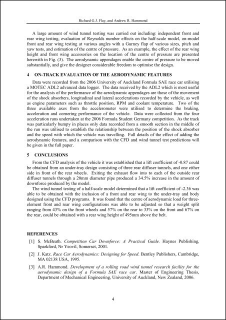
Richard G.J. Flay, and Andrew R. HammondA large amount of wind tunnel testing was carried out including: independent front andrear wing testing, evaluation of Reynolds number effects on the half-scale model, on-modelfront and rear wing testing at various angles with a Gurney flap of various sizes, pitch andyaw tests, and estimation of the centre of pressure. As an example, the effect of the rear wingheight and front wing accessories on the location of the centre of pressure are presentedherewith in Fig. (3). The aerodynamic appendages enable the centre of pressure to be movedsubstantially, and give the designer considerable freedom to optimise the design.4 ON-TRACK EVALUATION <strong>OF</strong> THE <strong>AERODYNAMIC</strong> FEATURESData were recorded from the 2006 University of Auckland Formula <strong>SAE</strong> race car utilisinga MOTEC ADL2 advanced data logger. The data received by the ADL2 which is most usefulfor the analysis of the performance of the aerodynamic appendages are those of the movementof the shock absorbers, longitudinal and lateral accelerations recorded by the vehicle, as wellas engine parameters such as throttle position, RPM and coolant temperature. Two of thethree available axes from the accelerometer were utilised to determine the braking,acceleration and cornering performance of the vehicle. Data were collected from the fouracceleration runs undertaken at the 2006 Formula Student Germany competition. As the trackwas particularly bumpy in places only data recorded from a smooth section in the middle ofthe run was utilised to establish the relationship between the position of the shock absorberand the speed with which the vehicle was travelling. Full details of the effect of adding theaerodynamic features, and a comparison with the CFD and wind tunnel test predictions willbe given in the full paper.5 CONCLUSIONSFrom the CFD analysis of the vehicle it was established that a lift coefficient of -0.87 couldbe obtained from an under-tray design consisting of three rear diffuser tunnels, and one eitherside in front of the rear wheels. Exiting the exhaust flow into to each of the outside reardiffuser tunnels through a 20mm diameter pipe produced a 34.5% increase in the amount ofdownforce produced by the model.The wind tunnel testing of a half-scale model determined that a lift coefficient of -2.36 wasable to be obtained with the inclusion of a front and rear wing to the under-tray and bodydesigned using the CFD programs. It was found that the centre of aerodynamic load for threeelementfront and rear wing configurations was able to be adjusted so that a weight splitranging from 43% on the front wheels and 57% on the rear to 33% on the front and 67% onthe rear, could be obtained with a rear wing height of 495mm above the belt.REFERENCES[1] S. McBeath. Competition Car Downforce: A Practical Guide. Haynes Publishing,Sparkford, Nr Yeovil, Somerset, 2001.[2] J. Katz. Race Car Aerodynamics: Designing for Speed. Bentley Publishers, Cambridge,MA 02138 USA, 1995.[3] A.R. Hammond. Development of a rolling road wind tunnel research facility for theaerodynamic design of a Formula <strong>SAE</strong> race car. Master of Engineering Thesis,Department of Mechanical Engineering, University of Auckland, New Zealand, 2006.4