MAX GAS 170 P MAX GAS 170 P AB MAX GAS 250 P MAX GAS ...
MAX GAS 170 P MAX GAS 170 P AB MAX GAS 250 P MAX GAS ...
MAX GAS 170 P MAX GAS 170 P AB MAX GAS 250 P MAX GAS ...
- No tags were found...

Create successful ePaper yourself
Turn your PDF publications into a flip-book with our unique Google optimized e-Paper software.
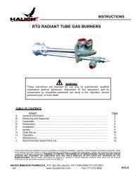
420010268500 Max Gas <strong>170</strong> - <strong>250</strong> P/P <strong>AB</strong> ITDIMENSIONI D’INGOMBRO<strong>MAX</strong> <strong>GAS</strong> <strong>170</strong>-<strong>250</strong> P<strong>MAX</strong> <strong>GAS</strong> <strong>170</strong>-<strong>250</strong> P<strong>AB</strong>AAD-D1BCBCP P NE190153FLOGMIMODELLO A B C D D1 E F G I L M N O P<strong>MAX</strong> <strong>GAS</strong> <strong>170</strong> P 392 202 190 180 280 290 125 201 106/130 106/130 M8 74 52 104<strong>MAX</strong> <strong>GAS</strong> <strong>170</strong> P<strong>AB</strong> 452 202 <strong>250</strong> 180 280 290 125 201 106/130 106/130 M8 74 52 104<strong>MAX</strong> <strong>GAS</strong> <strong>250</strong> P 392 202 190 180 280 290 125 201 106/130 106/130 M8 74 52 104<strong>MAX</strong> <strong>GAS</strong> <strong>250</strong> P<strong>AB</strong> 452 202 <strong>250</strong> 180 280 290 125 201 106/130 106/130 M8 74 52 104D = TESTA CORTA D1= TESTA LUNGACAMERA DI COMBUSTIONELunghezza camera di combustione4,03,02,01,00,60,50,40,30,2d=0,225d=0,3d=0,4d=0,5d=0,6d=0,7d=0,8I bruciatori sono stati omologati in camere di combustionesecondo le norme EN 676.Se le dimensioni della camera di combustione dellacaldaia, nella quale deve essere installato il bruciatore,è più piccola, consultare il costruttore del bruciatore.L’installazione deve essere fatta in conformitàalle disposizioni locali.(b)0,112 24 40 70 100 190 480 1200 2450(a)kW d = diametro camera di combustioneAVVIAMENTO DEL BRUCIATORECONTROLLI PRELIMINARIPrima di avviare il bruciatore effettuare i seguenti controlli : - Tipo di gas e pressione di alimentazione - Valvole gaschiuse. - La tenuta dei raccordi - Sfiato tubazione gas e controllo pressione entrata - Il cablaggio conforme allo schema efase e neutro rispettati - L’apertura del termostato caldaia ferma il bruciatore - La tenuta del focolare della caldaia perevitare l’entrata di aria - La tenuta del raccordo camino-caldaia - Condizioni del camino ( stagno, non ostruito,.......). Setutte queste condizioni sono soddisfatte avviare il bruciatore. L’apparecchiatura di controllo avvia il motore per effettuareilprelavaggio della camera di combustione. Durante questo periodo di prelavaggio (circa 30 secondi), l’apparecchiaturacontrolla che la pressione dell’aria sia corretta tramite il pressostato aria. Al termine, dà tensione al trasformatore eapre le valvole del gas. La formazione della fiamma deve avvenire e stabilizzare entro 3 secondi, che é il tempo di sicurezzadell’apparecchiatura. Controllare visivamente la fiamma prima di inserire qualsiasi strumento di controllo nel camino.Regolare e controllare al contatore la portata di gas necessaria alla caldaia. Adeguare alla portata del gas la portatadell’aria per una corretta combustione.CONSIGLI IMPORTANTITutti gli organi regolabili devono essere fissati dall’installatore dopo le regolazioni. Ad ogni regolazione controllate lacombustione al camino. I valori di CO2 devono essere circa 9,7(G20) 9,6(G25) 11,7(I3B) 11,7(I3P) ed il CO inferiore a75 ppm.3
53025IT420010268500 Max Gas <strong>170</strong> - <strong>250</strong> P/P <strong>AB</strong>Regolazione della portata gas all’accensione per i bruciatori <strong>MAX</strong> <strong>GAS</strong> <strong>170</strong>-<strong>250</strong>La portata termica all’accensione per questi bruciatori deve essere inferiore a 120 kW oppure al rapporto tra la portata termicanominale ed il tempo di sicurezza dell’apparecchiatura (il tempo di accensione è assunto pari al tempo di sicurezza, cioè 3 secondi).La regolazione della portata termica all’accensione è effettuata dal costruttore, tuttavia, se si rendesse necessario intervenire su taleregolazione, occorrerà procedere nel modo seguente: - verificare che la portata termica del bruciatore, funzionante a pieno regime,sia quella corretta. - A bruciatore spento, scollegare il cavo di rivelazione fiamma dal relativo elettrodo, in modo da causare la chiusuraautomatica della valvola gas all’accensione, dopo il tempo di sicurezza. - Effettuare una lettura del contatore gas. - Accendere ilbruciatore ed attendere che vada in blocco dopo la ripetizione del ciclo di accensione. - Effettuare una seconda lettura del contatoreed annotare il numero di litri erogati. - La portata termica, in kW, erogata all’accensione sara uguale al rapporto, tra il numero dilitri erogati ed il tempo di sicurezza, moltiplicato per il fattore F (in funzione del tipo di gas utilizzato) riportato dalla tabella a lato.Se il valore, così ottenuto, è superiore a 120 kW bisognerà ridurre la portata iniziale della valvola del gas. Alla fine, ricollegare ilcavo di rivelazione fiamma al relativo elettrodo.<strong>GAS</strong> FG20 (metano) 34,02G25 -G30 (butano) 116G31 (propano) 88NOTA: nel caso in cui, a causa del tipo di visore del contatore, la misurazione dei litri di gas erogatifosse difficoltosa, è possibile ripetere più volte, in sequenza, la procedura descritta precedentemente,in modo tale da totalizzare un volume di gas significativo. In tal caso, la portata termicaall’accensione si otterrà moltiplicando il rapporto, tra il totale del numero di litri erogati ed ilnumero di tempi di sicurezza cumulati (cioè il valore del tempo di sicurezza moltiplicato per ilnumero delle accensioni), per il fattore F. Si vedano i seguenti esempi:Esempio A : Bruciatore <strong>MAX</strong> <strong>GAS</strong> <strong>170</strong>, a metano; portata termica nom. di 175 kW; tempo disicurezza di 3 secondi; si eseguono 4 accensioni in sequenza, per un totale di 41 l erogati. La portata termica all’accensione, in kW,sara: 41/(3x4)x34,02 = 116 kW e, quindi, corretta essendo inferiore a 120 kW.CALCOLO DELLA PORTATA DI FUNZIONAMENTO DEL BRUCIATOREPer calcolare la portata di funzionamento, in kW, del bruciatore, procedere nel modo seguente:- Controllare al contatore la quantità di litri erogati e la durata, in secondi, della lettura, quindiprocedere al calcolo della portata secondo la seguente formula: e x f = kWsREGOLAZIONE PRESSOSTATO ARIAIl pressostato aria deve essere regolato in modo che una insufficiente portata aria non facciasuperare il valore di CO a 1% in volume. Dopo aver regolato la portata del gas e attenutouna combustione ottimale(CO2 = 9,5 ÷ 9,8% e CO inferiore a 75 ppm), bisogna regolare il pressostato aria. Togliereil coperchio; durante il funzionamento del bruciatore coprire progressivamente l’aspirazionedell’aria con un cartone in modo da ottenere un valore di CO2 = 10,8 (G 20 - G25),13 (G 30 - G 31) e un CO inferiore a 5.000 ppm.Regolare il pressostato dell’aria fino all’arresto del bruciatore. Togliere il cartone dall’aspirazionedell’aria e fare ripartire il bruciatore. Rimettere quindi il coperchio.<strong>AB</strong>e = Litri di gass = Tempo in secondiG20 = 34,02G25 = 29,25G30 = 116G31 = 88f3,02,70,42,40,62,11,80,91,51,2REGOLAZIONE PRESSOSTATO <strong>GAS</strong>Regolare il pressostato ad una pressione del 50% della pressione nominaledel gas utilizzato.PRESSIONE NOMINALE :G 20 = 20 mbarG 25 = 25 mbarG 30 = 29 mbarG 31 = 37 mbarCD50452,54010351520SISTEMA DI RILEVAZIONE FIAMMA (LANDIS & STAEFA LGB 21/LGB 22)TermostatoMotorePressostato ariaTrasformatoreValvola gasFiamma‡ 30 s0,5 s3 sSegnale necessario in entrataSegnale in uscita dell’apparecchiatura4
420010268500 Max Gas <strong>170</strong> - <strong>250</strong> P/P <strong>AB</strong> ITConnection Diagramma diagram connessioni and control e collegamenti sequence interni of LME11… LME11...K1K2/1 K2/2 K3RESETSB / RW / GPALMZA B B´ C D7101 d 0 4 / 040 9R / WTpV1LPGPTSTBHSiNALMZV1EK27101a24e/0609FSEK2tw t10 t1 t3 t3nTSAt4AGK25...ALV...CPIDBR...EKEK2IONFSFSVGPHHSK1...4resistenza PTCSegnalazione di bloccoestermaValvola combustibileIndicatore di posizione chiusaCollegamentoPulsante di sblocco (interno)Pulsante di sblocco remotoElettrodo di rivelazioneSegnale di fiammaAmplificatore del segnale difiammaPressostato gasInteruttore principaleContatto ausiliario rele’Contatti dei rele’ di controlloKLLKLKPLPLRMRSTBSiWZZV<strong>AB</strong>-B´interniBassa fiammaSerranda ariaPosizione serranda ariaPressostato ariaTermostato alta/bassaMotore del bruciatoreTermostato di lavoroTermostato di sicurezzaFusibile esternoTermostato o pressostatolimiteTrasformatore di accensioneValvola gas pilotaComando inizio cicloIntervallo accensione fiammaCC-DDt1t3t3nt4t10TSAtwPosizione funzionamentobruciatoreFunzionamento bruciatoreSpegnimento comandato da Rtempo di preventilazionetempo di preaccensionetempo di postaccensioneintervallo prima del consensoal 2° stadioTempo disponibile per ilsegnale pressostato ariaTempo di sicurezzaall’accensioneTempo di attesaTabella codici LED multicoloreStato Codice colore ColoreStato di attesa ❍ ................................................................................... spentoFase di accensione ● ❍ ● ❍ ● ❍ ● ❍ ● ❍ ● ❍ ● ❍ ● ❍ ● ❍ ● ❍ ● ❍ giallo lampeggianteFunzionamento, fiamma ok . ❑................................................................................... verdeFunzionamento, fiamma non ok ❑ ❍ ❑ ❍ ❑ ❍ ❑ ❍ ❑ ❍ ❑ ❍ ❑ ❍ ❑ ❍ ❑ ❍ ❑ ❍ ❑ ❍ verde lampeggianteSegnale di fiamma estraneo ❑ ▲ ❑ ▲ ❑ ▲ ❑ ▲ ❑ ▲ ❑ ▲ ❑ ▲ ❑ ▲ ❑ ▲ ❑ ▲ ❑ ▲ verde-rossoBassa tensione ● ▲ ● ▲ ● ▲ ● ▲ ● ▲ ● ▲ ● ▲ ● ▲ ● ▲ ● ▲ ● ▲ giallo-rossoBlocco ▲................................................................................... rossoCodice di errore ▲ ❍ ▲ ❍ ▲ ❍ ▲ ❍ ▲ ❍ ▲ ❍ ▲ ❍ ▲ ❍ rosso lampeggianteTrasmissione codice di errore ▲ ▲ ▲ ▲ ▲ ▲ ▲ ▲ ▲ ▲ ▲ ▲ rosso lampeggiante veloceLegenda : ....... Accesa continua ▲ rosso ❑ verde ❍ Spenta ● gialloTabella codici erroriLampeggi «AL» Possible cause(LED) term. n°102 lampeggi on Assenza di fiamma al termine del tempo di sicurezza all’accensione «TSA»- elettrovalvole difettose - rilevatore fiamma difettoso- regolazione bruciatore errata - elettrodi difettosi3 lampeggi on Guasto pressostato aria- Mancanza del segnale pressostato aria dopo«t10»,- Contatti pressostato aria incollati in posizione di riposo4 lampeggi on Segnale fiamma estraneo5 lampeggi on Segnale pressostato aria fuori tempoContatti pressostato aria incollati in posizione di lavoro6 lampeggi on Non utilizzati7 lampeggi on Troppe mancanze di fiamma durante il funzionamento(superato il limite del n° di ripetizioni del ciclo) - elettrovalvole difettose.- rilevatore fiamma difettoso - regolazione bruciatore errata.8 lampeggi on Non utilizzati9 lampeggi on Non utilizzati10 lampeggi off Contatti in uscita difettosi o guasto del dispositivo interno od errore nel cablaggio14 lampeggi on Indicatore di posizione chiusa aperto5
43210IT420010268500 Max Gas <strong>170</strong> - <strong>250</strong> P/P <strong>AB</strong>REGOLAZIONE ARIA Max Gas <strong>170</strong>-<strong>250</strong> P+REGOLAZIONE TESTA DI COMBUSTIONE-<strong>AB</strong>-+Per regolare la portata d’aria agire sulla vite A secondo lenecessità. Girando in senso antiorario la portata aumenta; insenso orario diminuisce. Nota: vite B non utilizzata.SERVOCOMANDO ARIA ( SIEMENS SQN 75 ) <strong>MAX</strong> <strong>GAS</strong> <strong>170</strong>-<strong>250</strong> P<strong>AB</strong>Togliere il coperchio per accedere alle camme di regolazione. Lo spostamento delle camme vaeffettuato con l’ausilio dell’apposita chiavetta (in dotazione), e di un giravite a taglio.Descrizione :I - Camma (CELESTE) di regolazione della posizione serranda allo spegnimento(chiusura totale 0°).II - Camma ( ARANCIONE) di regolazione posizione di apertura in accensione e 1° fiamma(con giravite).III - Camma ( ROSSA) di regolazione posizione di apertura in 2° fiamma (potenza max).IV - Camma (NERA) di consenso all’apertura dell’elettrovalvola del 2° stadio.CONTROLLO SISTEMA DI RILEVAZIONE FIAMMAmin. 1,5 µA 1min. 3 µA 1LANDISLME 11 / LME 21LANDISLGB 21 / LGB 22A bruciatore spento inserire un microamperometro in corrente continua e scala 0÷50 o 0÷100 µA.Con il bruciatore in funzione, e regolato correttamente, il valore letto dovrà essere stabile e mai inferiore a1,5µA (LME 11/21) e 3 µA (LGB 21/22) .6
IT420010268500 Max Gas <strong>170</strong> - <strong>250</strong> P/P <strong>AB</strong>MANUTENZIONECONTROLLO ANNUALEIl controllo periodico del bruciatore (testa di combustione, elettrodi,ecc.) deve essere effettuato da personaleautorizzato una o due volte all’anno a secondo dell’utilizzo.Prima di procedere al controllo per la manutenzione del bruciatore è consigliabile verificare lo stato generaledel bruciatore e seguire le seguenti operazioni :- Togliere tensione al bruciatore (togliere la spina)- Chiudere il rubinetto di intercettazione gas- Togliere il coperchio del bruciatore, pulire la ventola e l’aspirazione dell’aria- Pulire la testa di combustione e controllare la posizione degli elettrodi- Rimontare i pezzi- Verificare la tenuta dei raccordi gas- Verificare il camino- Far ripartire il bruciatore- Controllare i parametri della combustione(CO2 = 9,7(G 20); 9,6(G 25); 11,7(G 30); 11,7(G 31),(CO = inferiore a 75 ppm)PRIMA DI OGNI INTERVENTO CONTROLLARE :- Che ci sia corrente elettrica nell’impianto e il bruciatore collegato.- Che la pressione del gas sia corretta e il rubinetto di intercettazione del gas aperto.- Che i sistemi di controllo siano regolarmente collegati.Se tutte queste condizioni sono soddisfatte , far partire il bruciatore premendo il pulsante di sblocco.Controllare il ciclo del bruciatore.IL BRUCIATORE NON SI AVVIA :- Controllare l’interruttore, i termostati, il motore, pressione gas.IL BRUCIATORE EFFETTUA LA PREVENTILAZIONE E AL TERMINE DEL CICLO VA INBLOCCO :- Controllare la pressione dell’aria e la ventola.- Controllare il pressostato aria.IL BRUCIATORE EFFETTUA LA PREVENTILAZIONE E NON ACCENDE :- Verificare il montaggio e la posizione degli elettrodi.- Verificare il cavo di accensione.- Verificare il trasformatore di accensione.- Verificare l’apparecchiatura di sicurezza.IL BRUCIATORE SI ACCENDE E DOPO IL TEMPO DI SICUREZZA VA IN BLOCCO :- Controllare fase e neutro che siano collegati correttamente.- Controllare l’elettrovalvole del gas.- Controllare la posizione dell’elettrodo di rivelazione e la sua connessione.- Controllare l’elettrodo di rivelazione.- Controllare l’apparecchiatura di sicurezza.IL BRUCIATORE SI ACCENDE E DOPO QUALCHE MINUTO DI FUNZIONAMENTO VA IN BLOCCO :- Controllare il regolatore di pressione e il filtro gas.- Controllare la pressione del gas con un manometro.- Controllare il valore di rivelazione (min 1,5/3 µA).8
EN420010268500 Max Gas <strong>170</strong> - <strong>250</strong> P/P <strong>AB</strong>OVERALL DIMENSIONS<strong>MAX</strong> <strong>GAS</strong> <strong>170</strong>-<strong>250</strong> P<strong>MAX</strong> <strong>GAS</strong> <strong>170</strong>-<strong>250</strong> P<strong>AB</strong>AAD-D1BCBCP P NE190153FLGOMIMODEL A B C D D1 E F G I L M N O P<strong>MAX</strong> <strong>GAS</strong> <strong>170</strong> P 392 202 190 180 280 290 125 201 106/130 106/130 M8 74 52 104<strong>MAX</strong> <strong>GAS</strong> <strong>170</strong> P<strong>AB</strong> 452 202 <strong>250</strong> 180 280 290 125 201 106/130 106/130 M8 74 52 104<strong>MAX</strong> <strong>GAS</strong> <strong>250</strong> P 392 202 190 180 280 290 125 201 106/130 106/130 M8 74 52 104<strong>MAX</strong> <strong>GAS</strong> <strong>250</strong> P<strong>AB</strong> 452 202 <strong>250</strong> 180 280 290 125 201 106/130 106/130 M8 74 52 104D = SHORT HEAD D1= LONG HEADInstallation must be carried out in compliance with the local provisionsLongueur chambre de combustion4,03,02,01,00,60,50,40,30,2d=0,225d=0,3d=0,4d=0,5d=0,6d=0,7d=0,8The burners have been certified in combustionchambers according to EN 676 standards.Consult the burner manufacturer if the combustionchamber of the boiler in which the burneris to be installed has smaller dimensions.L’installazione deve essere fatta inconformità alle disposizioni locali.(b)0,112 24 40 70 100 190 480 1200 2450(a) kW d = diam tre chambre de combustionSTARTING-UP THE BURNERPRELIMINARY CHECKSBefore starting up the boiler check the following: - gas type and feed pressure; - gas valves closed; - the seals in the pipefittings; - gas pipe breather and input pressure; - that the cable complies with the diagram and the phase and neutralwires correspond; - that the burner shuts down when the boiler thermostat opens; - the seal of the boiler furnace whichprevents air from entering; - the seal on the flue-boiler pipe fitting; - the condition of the flue (sealed, free from blockage,etc ). If all these conditions are present, start the burner. The control device starts the motor to carry out prewashingof the combustion chamber. During this prewash period (about 30 seconds) the device checks that air pressure is correctvia the air pressure switch. At the end, it supplies power to the transformer and opens the gas valves. The flame must belit and stabilize within 3 seconds, which is the device's safety time limit. Check to ensure the flame is lit before placingany control instrument in the flue. Adjust and check the gas flow necessary for the boiler at the meter. Adjust the airflow according to the gas flow to obtain correct combustion.IMPORTANT ADVICEAll adjustable parts must be fixed by the installer after making adjustments. Check flue combustion after each adjustiment.The CO2 values must be approx. 9.7 (G20) 9.6 (G25 11.7 (13B) 11.7 (13P) axld the CO must be less than 75ppm.10
53025CALCULATION OF WORKING OUTPUT OF THE BURNERTo calculate the burner’s working output, in kW, proceed as follows:- Check at the meter the quantity of supplied litres and the duration, in seconds, of thereading, then calculate the burner’s output through the following formula:420010268500 Max Gas <strong>170</strong> - <strong>250</strong> P/P <strong>AB</strong>Adjusting the gas flow rate at the ignition for burners <strong>MAX</strong> <strong>GAS</strong> <strong>170</strong>-<strong>250</strong>The thermal power at the ignition, for such a burners, must be smaller than 120 kW or else than the ratio between therated thermal power and control box’s safety time (ignition time is assumed equal to safety time, i.e. 3 seconds). Theadjustment of thermal power at the ignition is made by the manufacturer, anyhow, should it be necessary to interveneon such an adjustment, proceed as follows: - check that the thermal power of the burner at full running is the correct<strong>GAS</strong> FG20 (nat.gas) 34,02G25 -G30 (buthane) -G31 (propane) 88one. - With the burner switched off, disconnect the flame detection cable from relevantelectrode, so as to make the valve to automatically shut off at the ignition, after the safetytime. - Make a reading on the gas meter. - Start the burner and wait for the burner’s lockout, after the repetition of the ignition sequence. - Make a second reading on the meter,and note the number of delivered litres. - The delivered thermal power, at the ignition,will then be equal to the ratio, between the delivered litres and the safety time, multipliedby the F factor (as function of the type of gas used) read on the table at the side. If the value thus obtained is higherthan 120 kW it shall be necessary to reduce the gas valve’s initial flow rate. At the end, reconnect the flame detectioncable to its relevant electrode. NOTE: should it be difficult to measure the quantity of delivered litres of gas, due to theparticular meter’s dial, it is possible to repeat, sequentially, the above steps many times, so as to reach a significantamount of gas volume. In such a case, the thermal power at the ignition shall be obtained by multiplying the ratio,between the amount of delivered litres and the number of cumulated safety times (i.e. the value of the safety time multipliedby the number of ignitions) by the F factor. See the following examples: Example A: <strong>MAX</strong> <strong>GAS</strong> <strong>170</strong> burner, nat.gas; rated thermal power of 175 kW; safety time of 3 secs; a sequence of 4 ignitions is made, for a total amount of 41delivered litres. The thermal power at the ignition, in kW, shall be: 41/(3x4)x34,02 = 116 kW and therefore correct,being smaller than 120 kW.e x f = kWse = Litres of gass = Time in secondsfG20 = 34,02G25 = 29,25G30 = 116G31 = 88ENADJUSTING THE AIR PRESSURE SWITCHThe air pressure switch must be adjusted so that an insufficient air flow does not allowthe CO value to exceed 1% in volume. After having adjusted the gas flow and obtainedoptimum combustion (CO2 = 9.5 to 9.8% and a CO value of less than 75 ppm), the airpressure switch must be adjusted. Remove the cover with the burner operating, coverthe air intake progressively with a piece of cardboard to obtain a value of CO2 = 10.8(G20-G25)> 13 (G30-G31) and a CO value of less than 5,000 ppm. Adjust the airpressure switch until the burner shuts down. Remove the cardboard from the air intakeand start up the burner again. Replace the cover.<strong>AB</strong>3,02,70,42,40,62,11,80,91,51,2ADJUSTING THE <strong>GAS</strong> PRESSURE SWITCHAdjust the pressure switch to 50% of the rated pressure of the gas used.RARED PRESSURE: G 20 = 20 mbar G 25 = 25 mbarG 30 = 29 mbar G 31 = 37 mbar504540CD2,510351520(LANDIS & STAEFA LGB 21/LGB 22) UP CYCLEThermostatmotorAir pressure switchTransformerGas valveFlame‡ 30 s0,5 s113 sNecessary input signaloutput signal of the device
EN420010268500 Max Gas <strong>170</strong> - <strong>250</strong> P/P <strong>AB</strong>Connection diagram and control sequence of LME11…K1K2/1 K2/2 K3RESETA B B´ C DSB / RW / GPALMZ7101 d 0 4 / 040 9R / WTpV1LPGPTSTBHSiNALMZV1EK27101a24e/0609FSEK2tw t10 t1 t3 t3nTSAt4AGK25...ALV...CPIDBR...EKEK2IONFSFSVGPHHSK1...4KLLKPTC resistorError message (alarm)Fuel valveClosed Position IndicatorWire linkLockout reset button (internal)Remote lockout reset buttonIonization probeFlame signalFlame signal amplifierPressure switchMain switchAuxiliary contactor, relayInternal relaysLow-fireAir damperLKP Air damper positionLP Air pressure switchLR Load controllerM Fan motorR Control thermostat /pressurestatSTB Safety limit thermostatSi External pre-fuset TimeW Limit thermostat / pressureswitchZ Ignition transformerZV Pilot gas valveA Start command (switching onby «R»)B-B´ Interval for establishment ofCC-DDt1t3t3nt4t10TSAtwflameOperating position of burnerreachedBurner operation (generationof heat)Controlled shutdown by «R»Prepurge timePreignition timePostignition timeInterval between ignition«Off» and release of «V2»Specified time for air pressuresignalIgnition safety timeWaiting timeColor code table for multicolor signal lamp (LED)Status Color code ColorWaiting time «tw», other waiting states ❍ ................................................................................... OffIgnition phase, ignition controlled ● ❍ ● ❍ ● ❍ ● ❍ ● ❍ ● ❍ ● ❍ ● ❍ ● ❍ ● ❍ ● ❍ Flashing yellowOperation, flame o.k. ❑................................................................................... GreenOperation, flame not o.k. ❑ ❍ ❑ ❍ ❑ ❍ ❑ ❍ ❑ ❍ ❑ ❍ ❑ ❍ ❑ ❍ ❑ ❍ ❑ ❍ ❑ ❍ Flashing greenExtraneous light on burner startup ❑ ▲ ❑ ▲ ❑ ▲ ❑ ▲ ❑ ▲ ❑ ▲ ❑ ▲ ❑ ▲ ❑ ▲ ❑ ▲ ❑ ▲ Green-redUndervoltage ● ▲ ● ▲ ● ▲ ● ▲ ● ▲ ● ▲ ● ▲ ● ▲ ● ▲ ● ▲ ● ▲ Yellow-redFault, alarm ▲................................................................................... RedError code output (refer to «Error codetable») ▲ ❍ ▲ ❍ ▲ ❍ ▲ ❍ ▲ ❍ ▲ ❍ ▲ ❍ ▲ ❍ Flashing redInterface diagnostics ▲ ▲ ▲ ▲ ▲ ▲ ▲ ▲ ▲ ▲ ▲ ▲ Red flicker lightLegend: ....... Steady on ▲ Red ❑ Green ❍ Off ● YellowError code tableRed blink code of «AL» at Possible causesignal lamp (LED)) term. 102 blinks on No establishment of flame at the end of «TSA»- Faulty or soiled fuel valves - Faulty or soiled flame detector- Poor adjustment of burner, no fuel - Faulty ignition equipment3 blinks on «LP» faulty- Loss of air pressure signal after «t10», - «LP» welded in normal position4 blinks on Extraneous light when burner is started up5 blinks on Time out «LP»- «LP» welded in working position6 blinks on Free7 blinks on Too many losses of flame during operation(limitation of the number of repetitions)- Faulty or soiled fuel valves.- Faulty or soiled flame detector - Poor adjustment of burner.8 blinks on Free9 blinks on Free10 blinks off Wiring error or internal error, output contacts, other faults.14 blinks on CPI contact not closed12
43210AIR ADJUSTMENT Max Gas <strong>170</strong>-<strong>250</strong> P+420010268500 Max Gas <strong>170</strong> - <strong>250</strong> P/P <strong>AB</strong>SETTING THE FIRING HEADEN-<strong>AB</strong>-+To adjust air flow, turn the screw A as required. To reduceoutput, turn screw clockwise, to increase it turn screwcounterclockwise. Note: screw B not used.AIR SERVOMOTOR ( SIEMENS SQN 75 ) <strong>MAX</strong> <strong>GAS</strong> <strong>170</strong>-<strong>250</strong> P<strong>AB</strong>Remove cover to enter the adjusting cams. Adjust cams through the suitable key (onissue) and a screwdriver.I- Adjusting cam (BLUE) for air damper position on burner’s shutdown(total close 0°).II - Adjusting cam (ORANGE) for opening position in ignition and Low Flame(by the screwdriver).III- Adjusting cam (RED) for opening position in High Flame (max. output).IV - Adjusting cam (BLACK) to allow the opening of High flame solenoid valve.FLAME DETECTION SYSTEM CHECKmin. 1,5 µA 1min. 3 µA 1LANDISLME 11 / LME 21LANDISLGB 21 / LGB 22With the burner switched off, connect a DC microammeter with a 0÷50 or 0÷100 µA dial. When the burner is running,and is properly adjusted, the value read must be steady and never be smaller than 1,5 µA (LME 11/21) and 3µA (LGB 21/22).13
3 +1 0EN420010268500 Max Gas <strong>170</strong> - <strong>250</strong> P/P <strong>AB</strong>POSITION OF ELECTRODESIGNITIONELECTRODEASez. A3195 ±0.518AIONIZATIONPROBEMOUNTING TO THE BOILER3+–21TUBE DISASSEMBLY14
420010268500 Max Gas <strong>170</strong> - <strong>250</strong> P/P <strong>AB</strong>MAINTENANCEYEARLY INSPECTIONPeriodic inspection of the burner (combustion head, electrodes, etc.) must be carried out by authorised personnel onceor twice a year, depending of use. Before carrying out maintenance inspection on the burner, it is advisable to check itsgeneral condition and carry out the following operations:- Disconnect the burner from the power supply (remove the plug).- Close the gas cock.- Remove the burner cover, clean the fan and air intake.- Clean the combustion head and check the position of the electrodes.- Re-assemble the parts.- Check the seal on the gas pipe fittings.- Check the flue.- Restart the burner.- Check the combustion parameters (CO2 = 9.5 to 9.8),(CO = less than 75 ppm)ENBEFORE EACH INTERVENTION CHECK;- That the system is supplied with power and the burner connected.- That the gas pressure is correct and the gas cock open.- That the control systems are correctly connected.If all these conditions are present, start the burner by pressing the release button. Check the burner cycle.THE BURNER WILL NOT START;- Check the switch, thermostats, motor, gas pressure.THE BURNER PREVENTILATES AND LOCKS AT THE END OF THE CYCLE:- Check the air pressure and fan.- Check the air pressure switch.THE BURNER PREVENTILATES AND WILL NOT IGNITE:- Check the assembly and position of electrodes.- Check the ignition cable.- Check the ignition transformer.- Check the safety devices.THE BURNER STARTS UP AND LOCKS AFTER THE SAFETY TIME LIMIT:- Check that the phase and neutral wires are correctly connected.- Check the gas electrovalves.- Check the position of the detection electrode and its connection.- Check the detection electrode.- Check the safety devices.THE BURNER STARTS UP AND LOCKS AFTER RUNNING FOR A FEW MINUTES.- Check the pressure regulator and the gas filter.- Check the gas pressure with an ammeter.- Check the detection value (min 1,5/3 µA Landis).15
420010268500 Max Gas <strong>170</strong> - <strong>250</strong> P/P <strong>AB</strong>FRCARACTERISTIQUES OPERATIONNELLESModele : Max Gas <strong>170</strong> -<strong>250</strong>Famille du gazG20 G25 G31 G30Pression max. mbar 360 360 360 360Pression min. mbar 16 16 30 30Combustible gaz P.C.I. kcal/Nm 3 8.570 7.370 22.260 29.320Modele : Max Gas <strong>170</strong>Débit gaz max. 17,60 Nm 3 /h 20,47 Nm 3 /h 6,78 Nm 3 /h 5,14 Nm 3 /hmin. 5,53 Nm 3 /h 6,43 Nm 3 /h 2,13 Nm 3 /h 1,62 Nm 3 /hModello : Max Gas <strong>250</strong>Débit gaz max. 24,14 Nm 3 /h 28,19 Nm 3 /h 9,29 Nm 3 /h 7,06 Nm 3 /hmin. 5,53 Nm 3 /h 6,43 Nm 3 /h 2,13 Nm 3 /h 1,62 Nm 3 /h* : Les pressions minimum et maximum effectives dépendent de la rampe gaz associée au brûleur. Les valeurs sont reportées dans le manuelrampes gaz.CARACTERISTIQUES DU BRULEURMax Gas <strong>170</strong> P Max Gas <strong>170</strong> P <strong>AB</strong> Max Gas <strong>250</strong> P Max Gas <strong>250</strong> P <strong>AB</strong>Puissance thermique max. kW 175 175 240 240kcal/h 150.860 150.860 206.900 206.900Puissance thermique min. kW 55 55 55 55kcal/h 47.410 47.410 47.410 47.410Famille du gaz : AT I2H, I3B/P BE I2E(R)B, I3P DE I2E, I3B/P DK I2H, I3B/P SE I2H, I3B/PES I2H, I3P FI I2H, I3B/P FR I2Er, I3B/P GB I2H, I3B/P NL I2L, I3B/PGR I2H, I3B/P IE I2H, I3B/P IT I2H, I3B/P PT I2H, I3B/Pmbar6COURBE DE TRAVAILContrepression en chambre de combustion54321025<strong>MAX</strong> <strong>GAS</strong> <strong>170</strong> P<strong>MAX</strong> <strong>GAS</strong> <strong>250</strong> P50 75 100 125 150 175 200 225kcal/hx 1000mbar64060 80 100 120 140 160 180 200 220 240 260 280PuissancekWContrepression en chambre de combustion54321025<strong>MAX</strong> <strong>GAS</strong> <strong>170</strong> P<strong>AB</strong>/PR<strong>MAX</strong> <strong>GAS</strong> <strong>250</strong> P<strong>AB</strong>/PR50 75 100 125 150 175 200 225kcal/hx 10004060 80 100 120 140 160 180 200 220 240 260 280Puissance16kW
420010268500 Max Gas <strong>170</strong> - <strong>250</strong> P/P <strong>AB</strong>DIMENSIONS D'ENCOMBREMENTFR<strong>MAX</strong> <strong>GAS</strong> <strong>170</strong>-<strong>250</strong> P<strong>MAX</strong> <strong>GAS</strong> <strong>170</strong>-<strong>250</strong> P<strong>AB</strong>AAD-D1BCBCP P NE190153MODELE A B C D D1 E F G I L M N O P<strong>MAX</strong> <strong>GAS</strong> <strong>170</strong> P 392 202 190 180 280 290 125 201 106/130 106/130 M8 74 52 104<strong>MAX</strong> <strong>GAS</strong> <strong>170</strong> P<strong>AB</strong> 452 202 <strong>250</strong> 180 280 290 125 201 106/130 106/130 M8 74 52 104<strong>MAX</strong> <strong>GAS</strong> <strong>250</strong> P 392 202 190 180 280 290 125 201 106/130 106/130 M8 74 52 104<strong>MAX</strong> <strong>GAS</strong> <strong>250</strong> P<strong>AB</strong> 452 202 <strong>250</strong> 180 280 290 125 201 106/130 106/130 M8 74 52 104D = TETE COURTE D1= TETE LONGUEL’INSTALLATION DOIT ETRE FAIT SELOM LES DISPOSITIONS LOCALIES.4,03,02,01,00,60,50,40,30,2d=0,225d=0,3d=0,4d=0,5d=0,6d=0,7d=0,8(b)FLOGMILunguieur chambre de combustionLes bruleurs sont ete homologues dans la chambrede combustion selon les normes EN 676. Sile dimensions de la chambre de combustion de lacHaudiere, dans la quelle il faut installer le bruleur,estplus petite i l faut consulter le constructeurdu bruleur.0,112 24 40 70 100 190 480 1200 2450(a)kWd = diametre cambre di combustionDEMARRAGE DU BRULEURCONTROLES PRELIMINAIRESAvant de faire démarrer le brûleur, effectuer les contrôles suivants:• Type de gaz et pression d’alimentation.• Soupapes gaz fermées.• Etanchéité des raccords.• Purge canalisation gaz etcontrôle pression à l’entrée. • Que le câblage soit conforme au schéma et que la phase et le neutre soient respectés.• Quel’ouverture du thermostat chaudière arrête le brûleur.• L’étanchéité du foyer de la chaudière pour éviter l’entrée d’air. •L’étanchéité du raccord cheminée/ chaudière.• Les conditions de la cheminée (étanche, non bouchée, ...). Si toutes cesconditions sont remplies, faire démarrer le brûleur.Le boîtier de contrôle fait démarrer le moteur pour effectuer le prélavage de la chambre de combustion. Durant cetemps de prélavage (environ 30 secondes), le boîtier contrôle que la pression de l’air soit correcte à l’aide du pressostatair. A la fin de cette opération, il donne du courant au transformateur et ouvre les soupapes gaz. La flamme doit se formeret se stabiliser en 3 secondes, qui correspond au temps de sécurité de l’appareil. Contrôler la flamme de façonvisuelle avant d’installer un instrument de contrôle quelconque dans la cheminée.Régler et contrôler le débit de gaznécessaire à la chaudière sur le compteur. Adapter le débit d’air au débit du gaz pour une combustion correcte.CONSEILS IMPORTANTS: Tous les organes réglables doivent être fixés par l’installateur après les réglages.Contrôler la combustion dans la cheminée à chaque réglage.Les valeurs de CO2 doivent être d’environ 9,7 (G20) - 9,6 (G25) - 11,7 (l3B) - 11,7 (l3P) et le CO doit être inférieur à75 p.p.m.
53025420010268500 Max Gas <strong>170</strong> - <strong>250</strong> P/P <strong>AB</strong>FRRégulation de la portée thermique à l’allumage pour les brûleurs <strong>MAX</strong> <strong>GAS</strong> <strong>170</strong>-<strong>250</strong>GAZ FG20 (gaz nat.) 34,02G25 29,25G30 (butane) -G31 (propane) 88La portée thermique à l’allumage pour ces brûleurs doit être inférieure à 120 kW ou bien au rapport entre la portéethermique nominale et le temps de sécurité du coffret de sécurité (le temps d’allumage étant assumé égale au temps desécurité, à savoir 3 secondes). La régulation de la portée thermique à l’allumage est faite par le fabricant de toute façon,s’il fût nécessaire intervenir sur cette régulation il faudra proceder de la manière suivante: - vérifier que la portée thermiquedu brûleur fonctionnant à plein régime soit celle correcte. - Avec le brûleur éteint, débrancher le câble de détectionde flamme de son électrode, de façon à provoquer la fermeture automatique de la vanne gaz à l’allumage, après le tempsde sécurité. - Effectuer une lecture du compteur gaz. - Allumer le brûleur et attendre qu’il se met en sécurité après larépétition de la séquence d’allumage. - Effectuer une deuxième lecture au compteur et noter le numéro des litres de gazdébités. - La portée thermique à l’allumage, en kW, sera égale au rapport, entre le numéro de litres débités et le tempsde sécurité, multiplié par le facteur F (en fonction du type de gaz) indiqué par le tableau à coté. Si la valeur, ainsi obtenue,est supérieure à 120 kW il faudra réduire la portée initiale de la vanne gaz. A la fin,rébrancher le câble de détection de flamme à son électrode. NOTE: si parfois, à cause dutype d’afficheur du compteur, la mensuration des litres de gaz débités fût difficile, il serapossible de répéter sequentiellement, à plusieures reprises, l’opération susdite, de façon àtotaliser un volume de gaz significatif. Dans ce cas, la portée thermique à l’allumage seraobtenue en multipliant le rapport, entre le total du numéro des litres débités et le numérodes temps de sécurité (à savoir, la valeur du temps de sécurité multiplié par le numéro des allumages) par le facteur F.Voir aux exemples suivants: Exemple A : Brûleur <strong>MAX</strong> <strong>GAS</strong> <strong>170</strong>, gaz nat.; portée thermique nominale 175 kW; tempsde sécurité de 3 secondes; on effectue 4 allumages en séquence, pour un total de 41 l débités. La portée thermique àl’allumage, en kW, sera: 41/(3x4)x34,02 = 116 kW. Dans ce cas, la portée initiale est correcte.CALCUL DU DEBIT DE FONCTIONNEMENT DU BRULEURPour calculer le débit de fonctionnement, en kW, du brûleur, procéder de la manière suivante:- Vérifier au compteur la quantité de litres débités, ainsique la durée de la lecture, ensuite procéder au calcul du débit e x f = kWspar la formule suivante:ThermostatMoteure = Litres de gazs = Temps en secondesG20 = 34,02G25 = 29,25G30 = 116G31 = 88REGLAGE PRESSOSTAT AIRLe dispositif de surveillance d'air doit être réglé de telle manière qu'il interviene en cas d'insuffisance d'airavant que la teneur en CO des gaz de combustion ne dépasse 1% en volume. Après le réglage du débit gazet obtention d’une bonne hygiène de combustion (CO2 = 9,5÷9,8 % et CO inférieur à 75ppm) il faut régler le pressostat d'air. Enlever le couvercle du pressostat. Pendant la marchenormale du brûleur, couvrir l'aspiration d'air du brûleur à l'aide d'un morceau de carton, progressivementde maniére à obtenir une valeur de CO2 = 10,6 et le CO inférieur à 10.000Appm. Tourner progressivement le réglage du pressostat air jusqu'à l'arrêt du brûleur.BEnlever le morceau de carton de l'aspiration d'air et faire redémarrer le brûleur. Remettrele couvercle.RÉGLAGE PRESSOSTAT GAZEnlever le couvercle du pressostat. Pendant le fonctionnement du brûleur, mesurer la pressionsur le raccord du pressostat et fermer lentement la vanne d’arrêt gaz jusqu’ à ce que laCpression mesurée tombe de 50%. Serrer le bouton de réglage jusqu'à l'arrêt du brûleur.DRéouvrir la vanne d’arrêt. Remettre le couvercle.G 20 = 20 mbar G 25 = 25 mbar G 30 = 29 mbar G 31 = 37 mbarf3,02,70,4502,4452,50,62,140101,80,91,51,2351520SYSTEME DETECTION DE FLAMME (LANDIS &STAEFA LGB 21/LGB 22-LMG 21/LMG 22)18Pressostat airTransformateurVanne gazFlamme‡ 30 s0,5 sSignal necessaire en entreeSignal en sortie de la coffret de securit3 s
420010268500 Max Gas <strong>170</strong> - <strong>250</strong> P/P <strong>AB</strong>Connection Schéma interne diagram et déroulement and control sequence du programme of LME11… LME11...K1K2/1 K2/2 K3RESETSB / RW / GPALMZA B B´ C D7101 d 0 4 / 040 9FRR / WTpV1LPGPTSTBHSiNALMZV1EK27101a24e/0609FSEK2tw t10 t1 t3 t3nTSAt4AGK25...ALV...CPIDBR...EKEK2IONFSFSVGPHHSK1...4KLThermistance PTCSignalisation de défaut ou dedérangement (alarme)Vanne de combustibleIndicateur de la position ArrêtShuntTouche de déverrouillage interneTouche de déverrouillage àdistanceSonde d'ionisationSignal de flammeAmplificateur de signal de flammeManostat de gazInterrupteur principalContacteur auxiliaire, relaisRelais internesfaible chargeLKLKPLPLRMRSTBSiWZZV<strong>AB</strong>-B´Volet d'airPosition du volet d'airPressostat airRégulateur de puissanceMoteur de ventilateurRégulateur de température ou depressionLimiteur de température desécuritéFusible externeThermostat de sécurité oupressostatTransformateur d'allumageVanne d'allumageOrdre de démarrageIntervalle pour la formation deflammeCC-DDt1t3t3nt4t10TSAtwPosition de fonctionnement dubrûleur atteinteFonctionnement du brûleurArrêt par régulation par "R"Temps de pré-ventilationTemps de préallumageTemps de post-allumageIntervalle entre allumage «Arrêté»et «vanne de combustible 2»libéréeTemps prescrit pour lasignalisation de pression d'airTemps de sécurité au démarrageTemps d'attenteTable de codes de couleur de la LED multicoloreÉtat Code couleur CouleurTemps d'attente "tw", divers états d'attente ❍ ................................................................................... éteintPhase d'allumage, allumage commandé ● ❍ ● ❍ ● ❍ ● ❍ ● ❍ ● ❍ ● ❍ ● ❍ ● ❍ ● ❍ ● ❍ clignote jauneFonctionnement, flamme correcte ❑................................................................................... vertFonctionnement, flamme défectueuse ❑ ❍ ❑ ❍ ❑ ❍ ❑ ❍ ❑ ❍ ❑ ❍ ❑ ❍ ❑ ❍ ❑ ❍ ❑ ❍ ❑ ❍ clignote vertLumière parasite pendant le démarrage dubrûleur ❑ ▲ ❑ ▲ ❑ ▲ ❑ ▲ ❑ ▲ ❑ ▲ ❑ ▲ ❑ ▲ ❑ ▲ ❑ ▲ ❑ ▲ vert-rougeSous-tension ● ▲ ● ▲ ● ▲ ● ▲ ● ▲ ● ▲ ● ▲ ● ▲ ● ▲ ● ▲ ● ▲ jaune-rougeDéfaut, alarme ▲................................................................................... rougeSignalisation selon code, cf. "Tableau descodes de dérangement" ▲ ❍ ▲ ❍ ▲ ❍ ▲ ❍ ▲ ❍ ▲ ❍ ▲ ❍ ▲ ❍ clignote rougeDiagnostic d'interface ▲ ▲ ▲ ▲ ▲ ▲ ▲ ▲ ▲ ▲ ▲ ▲ faible clignotement rougeLégende : ....... permanent ▲ rouge ❑ vert ❍ éteint ● jauneTableau des codes de dérangementCode de clignotement «AL» Cause possible(LED) sur borne 10clignote 2 fois EN Pas de formation de flamme à la fin de "TSA"- Défaut ou encrassement vannes de combustible - sonde de flamme défectueuseou encrassée - mauvais réglage du brûleur, pas de combustible - dispositif d'allumage défectueuxclignote 3 fois EN Erreur «LP»- Chute de pression d'air à l'issue de «t10»,- «LP» collé en position de reposclignote 4 fois EN lumière parasite au démarrage du brûleurclignote 5 fois EN Surveillance du temps «Pressostat air»- «LP» collé en position travailclignote 6 fois EN Libéréeclignote 7 fois EN Disparition de flamme trop fréquente en cours de fonctionnement (limitation desrépétitions) - Défaut ou encrassement des vannes de combustible- Défaut ou encrassement de sonde de flamme - Mauvais réglage du brûleurclignote 8 fois EN Libéréclignote 9 fois EN Libéréclignote 10 fois Hors Erreur de câblage ou défaut interne, contacts de sortie,autres défautsclignote 14 fois EN Le contact CPI n'est pas fermé19
43210FR420010268500 Max Gas <strong>170</strong> - <strong>250</strong> P/P <strong>AB</strong>RÉGLAGE AIR PRIMAIRE Max Gas <strong>170</strong>-<strong>250</strong> P+RÉGLAGE TETE DE COMBUSTION-<strong>AB</strong>-+Pour régler le débit d'air tourner la vis A selon la necessité.En tournant à gauche, le débit augmente; en tournantà droite diminue. Note: vis B non utilisé.SERVOMOTEUR AIR ( SIEMENS SQN 75 ) <strong>MAX</strong> <strong>GAS</strong> <strong>170</strong>-<strong>250</strong> P<strong>AB</strong>Enlever le couvercle pour accéder aux cames. Réguler les cames à l’aide de la clé appropriée(endotation) et du tournevis.I - Came de régulation (BLEUE) pour la position du clapet d’air à extinction du brûleur(fermer total 0°).II - Came de régulation (ORANGE) pour l’ouverture en allumage et 1e Allure(avec le tournevis).III - Came de régulation (ROUGE) pour la position d’ouverture en 2e Allure(puissance max.).IV - Came de régulation (NOIRE) pour le consentement à l’ouverture de l’électrovannede 2e Allure.CONTROLE SYSTEME DETECTION DE FLAMMEmin. 1,5 µA 1min. 3 µA 1LANDISLME 11 / LME 21LANDISLGB 21 / LGB 22Avec le brûleur éteint, brancher un microamperomètre à courante continue et échelle 0÷50 ou 0÷100 µA. Avec le brûleuren fonction, et dûment régulé, la valeur lue doit être stable et ne jamais être inférieure à 1,5 µA (LME 11/21) en 3µA (LGB 21/22).20
3 +1 0420010268500 Max Gas <strong>170</strong> - <strong>250</strong> P/P <strong>AB</strong>POSITIONNEMENT DES ELECTRODESELECTRODED’ALLUMAGEASez. A3FR195 ±0.518ASONDE DEIONISATIONMONTAGE DU BRULEUR3+–21DEMONTAGE DU GUEULARD21
420010268500 Max Gas <strong>170</strong> - <strong>250</strong> P/P <strong>AB</strong>FRMAINTENANCECONTROLE ANNUEL:Le contrôle périodique du brûleur (tête de combustion, électrodes etc.) doit être fait, par des techniciens autorisés, uneou deux fois par an, suivant les conditions d’utilisation. Avant de procéder avec les opérations d’entretien, il seraitsouhaitable d’effectuer une vérification de l’état général du brûleur de la manière suivante:- Débrancher le brûleur du réseau.- Fermer le robinet du gaz.- Enlever le couvercle du brûleur et nettoyer le ventilateur ainsi que le conduit d’aspiration d’air.- Nettoyer la tête de combustion et vérifier la position des électrodes.- Remonter le tout.- Vérifier l’étanchéité des raccords gaz.- Contrôler la cheminée.- Redémarrer le brûleur et en contrôler les paramètres de combustion(CO2 = 9,7% (G 20); 11,7% (G 30); 11,7% (G 31); CO inférieur a 75 ppm).Avant de chaque intervention contrôler:Qu’il y soit courante électrique dans l’installation et que le brûleur soit branché.- Que la pression du gaz soit celle correcte et que le robinet du gaz soit ouvert.- Que les dispositifs de contrôle soient dûment branchés.- Lorsque toutes ces conditions sont satisfaites, démarrer le brûleur en appuyant sur le bouton du réarmement de lamise en sécurité, et en vérifier la séquence d’allumage.BREVE GUIDE AU DÉPANNAGE:- Le brûleur ne démarre pas:contrôler l’interrupteur d’allumage, les thermostats, le moteur, la pression du gaz et le dispositif du contrôle d’étanchéité(s’il y en a).- Le brûleur effectue le prébalayage mais se met en sécurité à la fin du cycle:contrôler la pression de l’air, le ventilateur ainsi que le pressostat air.- Le brûleur effectue le prébalayage mais ne s’allume pas:vérifier le montage et la position des électrodes, le câble d’allumage, le transformateur d’allumage, le coffret de sécuritéet les électrovannes du gaz.- Le brûleur s’allume mais se met en sécurité après l’écoulement du temps de sécurité:contrôler que la phase et le neutre soient dûment connectés; contrôler position et connexion de la sonde d'ionisation;vérifier le coffret de sécurité.- Le brûleur s’allume normalement mais se met en sécurité après quelques minutes de fonctionnement: contrôler lerégulateur de pression et le filtre gaz; contrôler la pression du gaz; contrôler la valeur de détection (1,5 / 3µA min.);contrôler les valeurs de la combustion.22
420010268500 Max Gas <strong>170</strong> - <strong>250</strong> P/P <strong>AB</strong>CARACTERÍSTICAS OPERATIVASModelo : Max Gas <strong>170</strong> -<strong>250</strong>Familia de gasG20 G25 G31 G30Presión gas máx.* mbar 360 360 360 360Presión gas mín.* mbar 16 16 30 30Combustible gas P.C.I. kcal/Nm 3 8.570 7.370 22.260 29.320Modelo : Max Gas <strong>170</strong>Caudal gas max. 17,60 Nm 3 /h 20,47 Nm 3 /h 6,78 Nm 3 /h 5,14 Nm 3 /hmin. 5,53 Nm 3 /h 6,43 Nm 3 /h 2,13 Nm 3 /h 1,62 Nm 3 /hModelo : Max Gas <strong>250</strong>Caudal gas max. 24,14 Nm 3 /h 28,19 Nm 3 /h 9,29 Nm 3 /h 7,06 Nm 3 /hmin. 5,53 Nm 3 /h 6,43 Nm 3 /h 2,13 Nm 3 /h 1,62 Nm 3 /h* : Las presiones mínima y máxima efetivas dependen del circuito del gas montado en el quemador. Los valores se encuentran en elmanual del circuito del gas.CARACTERISTICAS TECNICASMax Gas <strong>170</strong> P Max Gas <strong>170</strong> P <strong>AB</strong> Max Gas <strong>250</strong> P Max Gas <strong>250</strong> P <strong>AB</strong>Potencia térmica máx. kW 175 175 240 240kcal/h 150.860 150.860 206.900 206.900Potencia térmica míx. kW 55 55 55 55kcal/h 47.410 47.410 47.410 47.410ESFamilia de gas : AT I2H, I3B/P BE I2E(R)B, I3P DE I2E, I3B/P DK I2H, I3B/P SE I2H, I3B/PES I2H, I3P FI I2H, I3B/P FR I2Er, I3B/P GB I2H, I3B/P NL I2L, I3B/PGR I2H, I3B/P IE I2H, I3B/P IT I2H, I3B/P PT I2H, I3B/Pmbar6CAMPO DE TR<strong>AB</strong>AJOContropresión en cámara de combustión54321025<strong>MAX</strong> <strong>GAS</strong> <strong>170</strong> P<strong>MAX</strong> <strong>GAS</strong> <strong>250</strong> P50 75 100 125 150 175 200 225kcal/hx 1000mbar64060 80 100 120 140 160 180 200 220 240 260 280PotenciakWContropresión en cámara de combustión54321<strong>MAX</strong> <strong>GAS</strong> <strong>170</strong> P<strong>AB</strong>/PR<strong>MAX</strong> <strong>GAS</strong> <strong>250</strong> P<strong>AB</strong>/PR02550 75 100 125 150 175 200 225kcal/hx 10004060 80 100 120 140 160 180 200 220 240 260 280Potencia23kW
420010268500 Max Gas <strong>170</strong> - <strong>250</strong> P/P <strong>AB</strong>DIMENSIONES TOTALESES<strong>MAX</strong> <strong>GAS</strong> <strong>170</strong>-<strong>250</strong> P<strong>MAX</strong> <strong>GAS</strong> <strong>170</strong>-<strong>250</strong> P<strong>AB</strong>AAD-D1BCBCP P NE190153FLOGMIMODELO A B C D D1 E F G I L M N O P<strong>MAX</strong> <strong>GAS</strong> <strong>170</strong> P 392 202 190 180 280 290 125 201 106/130 106/130 M8 74 52 104<strong>MAX</strong> <strong>GAS</strong> <strong>170</strong> P<strong>AB</strong> 452 202 <strong>250</strong> 180 280 290 125 201 106/130 106/130 M8 74 52 104<strong>MAX</strong> <strong>GAS</strong> <strong>250</strong> P 392 202 190 180 280 290 125 201 106/130 106/130 M8 74 52 104<strong>MAX</strong> <strong>GAS</strong> <strong>250</strong> P<strong>AB</strong> 452 202 <strong>250</strong> 180 280 290 125 201 106/130 106/130 M8 74 52 104D = C<strong>AB</strong>EZA CORTA D1= C<strong>AB</strong>EZA LARGALa instalación debe ser efectuada en conformidad a las disposiciones locales.Largueza Lunghezza de camera la cámara di combustionede combustión4,03,02,01,00,60,50,40,30,2d=0,225d=0,3d=0,4d=0,5d=0,6d=0,7d=0,8Los quemadores han sido homologados en cámarasde combustión según las normas EN 676. Silas medidas de la cámara de combustión de lacaldera, en la cual debe ser instalado el quemador,son más pequeñas, consultar al fabricantedel quemador.(b)0,112 24 40 70 100 190 480 1200 2450(a)kW d = diametro Diámetro camera de la cámara di combustione de combustiónPUESTA EN MARCHA DEL QUEMADORCONTROLES PRELIMINARESAntes de poner en marcha el quemador, efectuar los siguientes controles:• Tipo de gas y presión de alimentación. • Válvulas del gas cerradas. • Estanqueidad de las conexiones.• Purgar la tuberíadel gas y control de la presión en ingreso. • Que el cableado sea conforme al esquema, con respeto de la fase y neutro.•Que el quemador se pare cuando el termostato caldera se abre. • La estanqueidad del hogar para evitar el ingreso de aire.• La estanqueidad de la conexión caldera-chimenea. • La condición de la chimenea (estanco, non obstruido...). Al cumplirde todas estas condiciones poner en marcha el quemador. El equipo de control arranca el quemador para efectuar elprebarrido de la cámara de combustión. Durante este periodo de prebarrido (cerca de los 30 segundos) el equipo compruebaque la presión del aire sea correcta por medio del presostato del aire. Al termino alimenta el transformador y abrelas válvulas del gas. La formación de la llama tiene que efectuarse y estabilizarse dentro de los 3 secundos, que es el tiempode seguridad del equipo. Averiguar a vista la presencia de la llama antes de introducir cualquiera instrumentación decontrol. Regular y comprobar el caudal del gas necesario a la caldera por medio del contador.Adecuar el caudal del aire al caudal del gas para obtener una combustión correcta.ADVERTENCIAS IMPORTANTESTodos los equipos regulables tienen que ser fijados por el instalador después de cada regulación. Por cada regulacióncomprobar la combustión a la chimenea. Los valores de CO2 deben ser cerca de 9,7 (G20) 9,6 (G25) 11,7 (13B)11,7(13P) y el CO inferior a los 75ppm.24
53025420010268500 Max Gas <strong>170</strong> - <strong>250</strong> P/P <strong>AB</strong>Regulación del caudal de gas al encendido para los quemadores <strong>MAX</strong> <strong>GAS</strong> <strong>170</strong>-<strong>250</strong><strong>GAS</strong> FG20 (gas nat.) 34,02G25 -G30 (butano) -G31 (propano) 88El caudal del gas al encendido para estos quemadores tiene que ser inferior a 120 kW o bien al razón entre el caudal térmiconominal y el tiempo de seguridad del equipo de control (el tiempo de encendido es considerado igual al tiempo deseguridad, o sea 3 segundos). La regulación del caudal térmico al encendido es echa por el fabricante, de todas formas, sifuese necesario intervenir sobre esta regulación, proceder de la siguiente manera: - comprobar que el caudal térmico delquemador funcionando a régimen lleno sea el correcto. - Con el quemador apagado, desconectar el cable de detecciónde llama de su electrodo, para provocar el cierre automático de la válvula gas al encendido, después del tiempo de seguridad.Efectuar una lectura del contador de gas. - Arrancar el quemador y atender que se ponga en seguridad después de larepetición de la secuencia de encendido. - Efectuar una segunda lectura del contador y tomar nota del numero de litrossuministrados. - El caudal térmico, en kW, suministrado al encendido será, luego, igual al razón, entre el numero delitros suministrados y el tiempo de seguridad, multiplicado por el factor F (en función del tipo de gas utilizado), indicadopor la tabla a lado. Si el resultado, así obtenido, es superior a 120 kW será necesarioreducir el caudal inicial de la válvula de gas. Al finar, conectar nuevamente el cable dedetección de llama a su electrodo. NOTA: en el caso de que, por causa del tipo de cuadrantedel contador, la medición del numero de litros suministrados fuese dificultosa, esposible repetir más veces la secuencia describida anteriormente, de modo de totalizar unnumero de litros de gas significativo. En este caso, el caudal térmico al encendido seráobtenido multiplicando el razón, entre el total del numero de litros suministrados y el numero de tiempos de seguridadacumulados (o sea el valor del tiempo de seguridad multiplicado por el numero de encendidos) por el factor F. Ver a losejemplos siguientes: Ejemplo B: Quemador <strong>MAX</strong> <strong>170</strong> gas nat.; caudal térmico nominal de 175 kW; tiempo de seguridadde 3 segundos; se efectúan 4 encendidos en secuencia, por un total de 41 l suministrados. El caudal térmico alencendido, en kW, será, luego: 41/(3x4)x34,02 = 116 kW. En este caso, el caudal inicial es correcto.CALCULO DE LA POTENCIA DE FUNCIONAMIENTO DEL QUEMADORPara calcular la potencia de funcionamiento, en kW, del quemador, proceder de la manerasiguiente: Comprobar al contador la cantidad de litros suministrados y la duración, en segundos,de la lectura, luego proceder al calculo de la potencia con laformula siguiente:e x f = kWse = Litri di gass = Tempo in secondiG20 = 34,02G25 = 29,25G30 = 116G31 = 88fESREGULACIÓN DEL PRESÓSTATO AIREEl presóstato aire tiene que ser regulado de modo que un caudal de aire insuficiente nole permita de superar el valor de CO a 1% en volumen.Después de haber regulado el caudal del gas y haber obtenido una combustión optimal(CO2 = 9,5÷9,8% y CO inferior a 75 ppm), se necesita regular el presóstato del aire dela siguiente manera:- Remover la tapa del presóstato; durante la marcha del quemador, obstruir progresivamentela toma del aire con un tarjetón, de manera a obtener un valor de CO2 = 10,8(G20 - G25) 13 (G30 - G31) y un CO inferior a 5.000 ppm.- Regular el presóstato del aire hasta al apagado del quemador.- Remover el tarjetón de la toma del aire y reponer en marcha el quemador.- Remontar la tapa.REGULACIÓN DEL PRESÓSTATO <strong>GAS</strong>- Regular el presóstato a una presión del 50% de la presión nominal del gas utilizado.Presión Nominal: G 20 = 20 mbar , G 25 = 25 mbar , G 30 = 29 mbar , G 31 = 37 mbarACBD3,02,7500,4452,52,40,640102,11,80,9351,51,21520LANDIS & STAEFA LGB 21/LGB 22Term statoMotorPres stato aireTransformadorV lvula gasLlama‡ 30 s0,5 s3 sSeg al necesario en entradaSeg al a la salida de equipo25
420010268500 Max Gas <strong>170</strong> - <strong>250</strong> P/P <strong>AB</strong>Connection Diagrama de diagram conexión and control y secuencia sequence de control of LME11… LME11…ESK1K2/1 K2/2 K3RESETSB / RW / GPALMZA B B´ C D7101 d 0 4 / 040 9R / WTpV1LPGPTSTBHSiNALMZV1EK27101a24e/0609FSEK2tw t10 t1 t3 t3nTSAt4AGK25...ALV...CPIDBR...EKEK2IONFSFSVGPHHSK1...4Resistencia PTCMensaje de error (alarma)Válvula de combustibleIndicador de posición cerradoUnión de cablesBotón de ajuste de cierre eléctricoremoto (interno))Botón de ajuste de cierre eléctricoremotoSonda de IonizaciónSeñal de llamaAmplificador de la señal de llamaInterruptor de presión de gasInterruptor principalContactor auxiliar, reléRelés InternosKL Baja combustiónLK Compuerta (damper) de aireLKP Posición de la compuesta de aireLP Interruptor de presión de aireLR Controlador de cargaM Motor del ventiladorR Termostato de control /presostatoSTB Termostato límite de seguridadSi Fusible externoW Termostato límite / interruptor depresiónZ Transformador de igniciónZV Vávula de gas pilotoA Comando de arranqueB-B´ Intervalo para el establecimientoCC-DDt1t3t3nt4t10TSAtwde llamaPosición de operación delquemador alcanzadaOperación del quemador(generación de calor)Parada controlada mediante «R»Tiempo de pre-purgaTiempo de preigniciónTiempo de post-igniciónIntervalo entre ignición«apagada» y liberación de «BV2»Tiempo especificado para la señalde presión de aireTiempo de seguridad de igniciónTiempo de esperaTabla de códigos de color para luz de señal multicolor (LED)Estado Código de Color ColorTiempo de espera «tw», otros estadosde espera ❍ ................................................................................... ApagadoFase de ignición, ignición controlada ● ❍ ● ❍ ● ❍ ● ❍ ● ❍ ● ❍ ● ❍ ● ❍ ● ❍ ● ❍ ● ❍ Amarillo intermitenteOperación, llama correcta ❑................................................................................... VerdeOperación, llama no correcta ❑ ❍ ❑ ❍ ❑ ❍ ❑ ❍ ❑ ❍ ❑ ❍ ❑ ❍ ❑ ❍ ❑ ❍ ❑ ❍ ❑ ❍ Verde intermitenteExtraña luz en arranque del quemador ❑ ▲ ❑ ▲ ❑ ▲ ❑ ▲ ❑ ▲ ❑ ▲ ❑ ▲ ❑ ▲ ❑ ▲ ❑ ▲ ❑ ▲ Verde-rojoBajo voltaje ● ▲ ● ▲ ● ▲ ● ▲ ● ▲ ● ▲ ● ▲ ● ▲ ● ▲ ● ▲ ● ▲ Amarillo-rojoAvería, alarma ▲................................................................................... RojoSalida de código de error (véase «Tablade códigos de error») ▲ ❍ ▲ ❍ ▲ ❍ ▲ ❍ ▲ ❍ ▲ ❍ ▲ ❍ ▲ ❍ Rojo intermitenteInterface diagnostics ▲ ▲ ▲ ▲ ▲ ▲ ▲ ▲ ▲ ▲ ▲ ▲ Parpadeo de Luz rojaLeyenda : ....... Encendido ▲ Rojo ❑ Verde ❍ Apagado ● AmarilloTabla de códigos de errorCódigo de parpadeo «AL» en Posible causa(LED) term. 102 parpadeos Encendido No establecimiento de llama en el extremo de «TSA»- Válvulas de combustible averiadas o sucias - Detector de llama averiado o sucio- Ajuste pobre del quemador. No hay combustible- Equipamiento de ignición averiado3 parpadeos Encendido «LP» averiado- Pérdida de señal de presión de aire después de «t10»- «LP» se suelda en posición normal4 parpadeos Encendido Luz extraña en el arranque del quemador5 parpadeos Encendido Tiempo muerto «LP»- «LP» se suelda en la posición de trabajo6 parpadeos Encendido Libre7 parpadeos Encendido Demasiadas pérdidas de llama durante la operación (limitación de repeticiones)- Válvulas de combustible averiadas o sucias - Detector de llama averiado o sucio- Ajuste pobre del quemador.8 parpadeos Encendido Libre9 parpadeos Encendido Libre10 parpadeos Apagado Error de cableado o error interno, contactos de salida, otras averías14 parpadeos Encendido Contacto CPI no cerrado26
43210REGULACIÓN AIRE Max Gas <strong>170</strong>-<strong>250</strong> P-+420010268500 Max Gas <strong>170</strong> - <strong>250</strong> P/P <strong>AB</strong>REGULACIÓN C<strong>AB</strong>EZA DE COMBUSTIONES<strong>AB</strong>-+Para regular el caudal del aire girar el tornillo A según senecesite. Atornillando, el caudal del aire disminuye, desatornillandoaumenta. Nota: tornillo B non utilizado.SERVOMOTOR AIRE ( SIEMENS SQN 75 ) <strong>MAX</strong> <strong>GAS</strong> <strong>170</strong>-<strong>250</strong> P<strong>AB</strong>Sacar la tapa para acceder a las levas de regulación. Regular las levas por medio de su llave desuministro y un destornillador.I - Leva de regulación (AZUL) para la posición del cierre del aire a la parada del quemador(chiusura totale 0°).II - Leva de regulación (ANARANJADA) para la posición de abertura en encendido yBaja Llama (con el destornillador)III - Leva de regulación (ROJA) para la posición de abertura en Alta Llama (potencia máx.)IV - Leva de regulación (NEGRA) para el consentimiento de la abertura de la electroválvula deAlta Llama.COMPROBACIÓN EQUIPO DE DETECCIÓN DE LLAMAmin. 1,5 µA 1min. 3 µA 1LANDISLME 11 / LME 21LANDISLGB 21 / LGB 22Con el quemador apagado, conectar un microamperómetro en corriente continua y escala 0÷50 o 0÷100 µA. Con elquemador funcionante y debidamente regulado, el valor leído debe ser estable y nunca inferior a 1,5 µA (LME 11/21)y 3 µA (LGB 21/22).27
3 +1 0420010268500 Max Gas <strong>170</strong> - <strong>250</strong> P/P <strong>AB</strong>POSICIÓN DE LOS ELECTRODOSESELECTRODO DEENCENDIDOASez. A3195 ±0.518AELECTRODO DECONTROL DE LLAMAINSTALACION EN LA CAMARA DE COMBUSTION3+–21DESMONTAJE DEL TUBO DE LLAMA28
420010268500 Max Gas <strong>170</strong> - <strong>250</strong> P/P <strong>AB</strong>MANTENIMIENTOCONTROL ANUAL:El control periódico del quemador (cabeza de combustión, electrodos etc.) tiene que ser efectuado por técnicos autorizadosuna o dos veces cada año, según la utilización del quemador. Antes de proceder con las operaciones de mantenimiento,es aconsejable comprobar el estado general del quemador actuando de la manera siguiente:ES- Desconectar la clavija del quemador de la red.- Cerrar la válvula de cierre del gas.- Sacar la tapa del quemador y limpiar ventilador y conducto de aspiración del aire.- Limpiar la cabeza de combustión y comprobar la posición de los electrodos.- Remontar el todo.- Comprobar la estanqueidad de las uniones del gas.- Comprobar la chimenea.- Arrancar el quemador y comprobar los parámetros de combustión(CO2 = 9,7% (G 20); 11,7% (G 30); 11,7% (G 31); CO inferior a 75 ppm).Antes de cada intervención comprobar:- Que hay corriente en la instalación y que el quemador sea conectado.- Que la presión del gas sea la correcta y la válvula de cierre esté abierta.- Que los equipos de control estén debidamente conectados.- Cuando todas estas condiciones se cumplen, arrancar el quemador presionando el botón de bloqueoy comprobar la secuencia de encendido.Breve guía de averías:- El quemador no arranca:comprobar el interruptor de arranque, los termostatos, el motor, la presión del gas, el equipo de control de estanqueidad(si lo hay).- El quemador efectúa el prebarrido pero se pone en seguridad al final del ciclo:comprobar la presión del aire, el ventilador y el presostato del aire.- El quemador efectúa el prebarrido pero no se enciende:comprobar el montaje y la posición de los electrodos, el cable de encendido, el transformador de encendido, el equipode control llama y las electroválvulas del gas.- El quemador se enciende pero se pone en seguridad al cumplir del tiempo de seguridad:comprobar que fase y neutro sean conectados correctamente; comprobar posición y conexión de la sonda de ionización;comprobar el equipo de control de llama.- El quemador se enciende normalmente pero se pone en seguridad después unos minutos defuncionamiento:comprobar el regulador de presión y el filtro del gas; controlar la presión del gas; controlar el valor de ionización (1,5 /3µA); comprobar los valores de la combustión.29
420010268500 Max Gas <strong>170</strong> - <strong>250</strong> P/P <strong>AB</strong>RUЭУААО ААодель : Max Gas <strong>170</strong> -<strong>250</strong> атегория газа II 2H 3+G20 G25 G31 G30аксимальное давление мбар 360 360 362 360инимальное давление мбар 16 16 30 30ид топлива: природный газ, нижняя ккал/м3 8.570 7.370 22.260 29.320теплота сгоранияодель : Max Gas <strong>170</strong>асход газа max. 17,60 м3/час 20,47 м3/час 6,78 м3/час 5,14 м3/часmin. 5,53 м3/час 6,43 м3/час 2,13 м3/час 1,62 м3/часодель : Max Gas <strong>250</strong>асход газа max. 24,14 м3/час 28,19 м3/час 9,29 м3/час 7,06 м3/часmin. 5,53 м3/час 6,43 м3/час 2,13 м3/час 1,62 м3/час*: актическое минимальное и максимальное давление зависят от газовой рампы, которая используется вместе с горелкой.оответствующие данные приведены в каталоге газовых рамп. ААMax Gas <strong>170</strong> P Max Gas <strong>170</strong> P <strong>AB</strong> Max Gas <strong>250</strong> P Max Gas <strong>250</strong> P <strong>AB</strong>аксимальная тепловая кт 175 175 240 240мощность ккал/час 150.860 150.860 206.900 206.900Termal power min. кт 55 55 55 55ккал/час 47.410 47.410 47.410 47.410АО ААО Оmbar6противодавление в камере сгорания54321<strong>MAX</strong> <strong>GAS</strong> <strong>170</strong> P<strong>MAX</strong> <strong>GAS</strong> <strong>250</strong> P02550 75 100 125 150 175 200 225kcal/hx 1000mbar64060 80 100 120 140 160 180 200 220 240 260 280ООЬkWпротиводавление в камере сгорания54321<strong>MAX</strong> <strong>GAS</strong> <strong>170</strong> P<strong>AB</strong>/PR<strong>MAX</strong> <strong>GAS</strong> <strong>250</strong> P<strong>AB</strong>/PR02550 75 100 125 150 175 200 225kcal/hx 10004060 80 100 120 140 160 180 200 220 240 260 280ООЬ30kW
420010268500 Max Gas <strong>170</strong> - <strong>250</strong> P/P <strong>AB</strong>АА А<strong>MAX</strong> <strong>GAS</strong> <strong>170</strong>-<strong>250</strong> P<strong>MAX</strong> <strong>GAS</strong> <strong>170</strong>-<strong>250</strong> P<strong>AB</strong>AAD-D1BCBCP P NE190153RUFGLOMIмодель A B C D D1 E F G I L M N O P<strong>MAX</strong> <strong>GAS</strong> <strong>170</strong> P 392 202 190 180 280 290 125 201 106/130 106/130 M8 74 52 104<strong>MAX</strong> <strong>GAS</strong> <strong>170</strong> P<strong>AB</strong> 452 202 <strong>250</strong> 180 280 290 125 201 106/130 106/130 M8 74 52 104<strong>MAX</strong> <strong>GAS</strong> <strong>250</strong> P 392 202 190 180 280 290 125 201 106/130 106/130 M8 74 52 104<strong>MAX</strong> <strong>GAS</strong> <strong>250</strong> P<strong>AB</strong> 452 202 <strong>250</strong> 180 280 290 125 201 106/130 106/130 M8 74 52 104D = короткая огневая головка D1 = длинная огневая головкаLunghezza длина camera камеры di combustione сгорания4,03,02,01,00,60,50,40,30,2d=0,225d=0,3d=0,4d=0,5d=0,6АА ОАЯd=0,7d=0,8орелки прошли испытания в камерах сгорания,соответствующих нормативам EN 676. ри меньшихразмерах камеры сгорания следует обращаться законсультацией к производителю.онтаж выполнять в соответствии с местныминормами и правилами.(b)0,112 24 40 70 100 190 480 1200 2450(a)kW d = diametro диаметр camera камеры di combustione сгоранияАУ ОАЬ ООЬеред тем, как приступить к пуску горелки: - , Удостоверьтесь, что тип и давление газа в сети соответствуют номинальным. -Удостоверьтесь, что газовые клапаны закрыты. - роверьте, обеспечена ли герметичность соединений.- травите воздух из газопровода и проверьте давление газа на входе. - роверьте, правильно ли выполнены электрическиесоединения и соблюдена ли полярность фазы и нуля. - Удостоверьтесь, что при размыкании контакта термостата котла горелкавыключается. - роверьте герметичность топки котла (в нее не должен попадать воздух). - роверьте герметичностьсоединения дымохода и котла и состояние дымохода (он должен быть герметичен и свободен от каких-либо препятствий ).сли все вышеупомянутые условия соблюдены, запустите горелку. Электронное оборудование контроля пламени запускаетдвигатель вентилятора горелки для выполнения предварительной продувки топки. о время предварительной продувки топки(около 30 секунд) аппаратура управления контролирует величину давления воздуха по сигналу от реле давления. о завершениипродувки контрольная аппаратура подает напряжение на трансформатор и дает команду на открывание газовых клапанов.акел должен сформироваться и стабилизироваться в течение 3 секунд, т.е. в течение контрольного времени аппаратуры.режде чем вводить контрольные приборы в дымоход, визуально проверьте состояние факела. Отрегулируйте и проверьте погазовому счетчику расход газа, требуемый для обеспечения нормальной работы котла. целью обеспечения качественногогорения на основании требуемого расхода газа отрегулируйте расход воздуха.А!се регулируемые устройства тарируются специалистами, выполняющими монтаж, и после запуска горелки должны бытьопломбированы. ри любом изменении регулировок следует произвести анализ дымовых газов в дымоходе. римерныезначения содержания CO2: 9,7 (G20) 9,6 (G25) 11,7 (I3B) 11,7 (I3P), CO – не более 75 ppm.31
53025420010268500 Max Gas <strong>170</strong> - <strong>250</strong> P/P <strong>AB</strong>RUегулировка расхода газа при розжиге горелок <strong>MAX</strong> <strong>GAS</strong> <strong>170</strong>-<strong>250</strong>епловая мощность данных горелок во время их запуска не должна превышать 120 кт либо номинальной тепловой мощности,деленной на время аварийного останова (контрольное время), которое определяется контрольной аппаратурой (время розжигапринимается равным времени аварийного останова, т.е. 3 секундам). епловая мощность во время розжига регулируется взаводских условиях. ем не менее, при необходимости изменить регулировки, действуйте следующим образом: - удостоверьтесь,А Fетан (G20) 34,02G25 -утан (G30) -ропан (G31) 88что тепловая мощность горелки во время ее работы на максимальной мощности, соответствуетноминальным показателям. - ыключите горелку, отсоедините провод обнаружения факела отсоответствующего электрода (это делается для того, чтобы во время розжига горелки поистечении контрольного времени произошел ее аварийный останов). - апишите показаниягазового счетчика. - апустите горелку и подождите до тех пор, когда произойдет аварийныйостанов, после автоматического повтора попытки розжига. - ще раз проверьте показаниягазового счетчика и определите количество израсходованного газа в литрах. - епловаямощность горелки в кт, произведенная при розжиге, будет равна количеству литров израсходованного газа, деленному напродолжительность контрольного времени и помноженному на коэффициент F, который зависит от типа используемого газа (см.таблицу слева). сли полученная расчетом величина превышает 120 кт, следует выполнить регулировку газового клапана,чтобы уменьшить расход газа при розжиге. о завершении проверки присоедините обратно провод обнаружения факела ксоответствующему электроду. А: сли конструкция смотрового окошка газового счетчика такова, что измерениеколичество газа в литрах затруднено, то вышеописанную процедуру можно повторить несколько раз подряд, чтобы получить всовокупности количество, газа достаточное для расчета. таком случае тепловая мощность при розжиге будет равнятьсяобщему количеству израсходованного газа в литрах, поделенному на совокупную продолжительность контрольного времени (т.е.длительность контрольной задержки, умноженная на количество розжигов) и помноженное на коэффициент F.апример: ример А: орелка <strong>MAX</strong> <strong>GAS</strong> <strong>170</strong>, работающая на метане, номинальная тепловая мощность - 175 кт, контрольноевремя - 3 секунды. роизводится 4 попытки розжига подряд, при этом расход газа составит 41 л. епловая мощность прирозжиге в кт составит: 41/(3x4)x34,02 = 116 кт. анное значение не превышает 120 к, следовательно, мощностьотрегулирована правильно.УОА АЯ ОУАеле давления воздуха должно быть отрегулировано таким образом, чтобы придефиците воздуха количество O не превышало 1% от объема. егулировка реледавления воздуха производится после того, когда отрегулирован расход газа идостигнуто оптимальное качество горения (CO2 = 9,5 Є9,8% и CO не более 75 ppm).нимите крышку, включите горелку и начните постепенно закрывать всасывающийвоздуховод до тех пор, пока содержание О2 не достигнет 10,8 (G 20 - G 25), 13 (G 30 -G 31), а количество CO будет находиться в пределах 5000 ppm. родолжайте вращатьрегулятор реле давления воздуха до тех пор, пока не произойдет останов горелки.Уберите картонку, закрывающую всасывающий воздуховод, и перезапустите горелку.Установите крышку на место.<strong>AB</strong>3,02,70,42,40,62,11,80,91,51,2УОА АЯ ААОтрегулируйте реле давления газа на 50% номинального давления используемого газа.ОАЬО А : G 20 = 20 мбарG 25 = 25 мбарG 30 = 29 мбарG 31 = 37 мбарCD50452,54010351520А ОО Оощность горелки в рабочем режимев кт рассчитывается следующимобразом: - амерьте по счетчикурасход газа в литрах и время замерав секундах. атем, подставляя вследующую формулу полученныевеличины, рассчитайте мощность вкт.e x f = kWse = кол-во газа в литрахs = время в секундахfG20 = 34,02G25 = 29,25G30 = 116G31 = 88А ОАУЯ АА(LANDIS & STAEFA LGB 21/LGB 22)Thermostat ермостатmotor вигательеле Air давления pressure воздуха switchTransformer азовый клапанGas рансформаторvalveазовый клапанFlame акел‡ 30 s 3 s0,5 sоступающий обязательный Necessary сигнал input signalигнал на выходе output аппаратуры signal of управления the device32
420010268500 Max Gas <strong>170</strong> - <strong>250</strong> P/P <strong>AB</strong>хема Connection подключения diagram и последовательность and control sequence управления of LME11… LME11…K1K2/1 K2/2 K3RESETSB / RW / GPALMZA B B´ C D7101 d 0 4 / 040 9RUR / WTpV1LPGPTSTBHSiNALMZV1EK27101a24e/0609FSEK2tw t10 t1 t3 t3nTSAt4AGK25...ALV...CPIDBR...EKEK2IONFSFSVGPHHSK1...4PTC резисторообщение об ошибке (тревога)опливный клапанндикатор закрытого положенияроволочная перемычканопка дистанционного сбросаблокировки (внутренняя)нопка дистанционного сбросаблокировкионизационный электродигнал пламениУсилитель сигнала пламениеле давлениялавный выключательополнительный контактор, реленутренние релеKLLKLKPLPLRMRSTBSiWZZVAизкая температураоздушная заслонкаоложение воздушной заслонкиеле давления воздухаонтроллер нагрузкиотор вентилятораУправляющее термореле / прессостатОграничивающий термостатбезопасностинешний плавкий предохранительОграничивающий термостат /реледавлениярансформатор зажиганияилотный (дежурный) газовый клапаноманда пуска (запускается через«R»)B-B’CC-DDt1t3t3nt4t10TSAtwнтервал стабилизации пламениабочее положение горелкидостигнутоабота горелки (тепловыделение)Управляемое отключениепосредством «R»ремя предпродувкиремя предзажиганияремя постзажиганиянтервал между зажиганием «ыкл»и пуском «V2»аданное время для сигнала давлениявоздухаремя безопасности зажиганияремя ожиданияаблица цветового кода для многоцветной сигнальной лампы (светодиод)остояние ветовой код ветремя ожидания «tw», другие состояния ожидания ❍ ................................................................................... выклаза зажигания, управляемое зажигание ● ❍ ● ❍ ● ❍ ● ❍ ● ❍ ● ❍ ● ❍ ● ❍ ● ❍ ● ❍ ● ❍ игающий желтыйабота, пламя в порядке ❑................................................................................... зеленыйабота, пламя не в порядке ❑ ❍ ❑ ❍ ❑ ❍ ❑ ❍ ❑ ❍ ❑ ❍ ❑ ❍ ❑ ❍ ❑ ❍ ❑ ❍ ❑ ❍ иг..зеленыйосторонний свет при пуске горелки ❑ ▲ ❑ ▲ ❑ ▲ ❑ ▲ ❑ ▲ ❑ ▲ ❑ ▲ ❑ ▲ ❑ ▲ ❑ ▲ ❑ ▲ зелено-красныйониженное напряжение ● ▲ ● ▲ ● ▲ ● ▲ ● ▲ ● ▲ ● ▲ ● ▲ ● ▲ ● ▲ ● ▲ желто-красныйОтказ, тревога ▲................................................................................... красныйывод кода ошибки (см. «аблицакода ошибки») ▲ ❍ ▲ ❍ ▲ ❍ ▲ ❍ ▲ ❍ ▲ ❍ ▲ ❍ ▲ ❍ игающийкрасныйиагностика интерфейса ▲ ▲ ▲ ▲ ▲ ▲ ▲ ▲ ▲ ▲ ▲ ▲ иг. рс. ветОбозначение : ....... остоянно вкл ▲ расный ❑ еленый ❍ ыкл ● елтыйаблица кода ошибкиод красного мигания «AL» на озможная причинасигнальной лампы(LED) клм. 102 мигания кл ет стабилизации пламени в конце «TSA»- неисправные или грязные топл. клапаны - неисправный или грязн. датчик пламени- плохая настройка горелки, нет топлива - неисправная система зажигания3 мигания кл еисправное реле «LP»- потеря сигнала давления воздуха после «t10»- контакты реле «LP» залипли в норм. положении4 мигания кл осторонний свет при пуске горелки5 мигания кл Time out «LP»залипание контактов «LP» в рабоч.положении6 мигания кл свободно7 мигания кл астое пропадание пламени во время работы (ограничение повторений)- неисправные или грязные топл. клапаны - неисправный или грязн. датчик пламени-плохая настройка горелки8 мигания кл свободно9 мигания кл свободно10 мигания ыкл Ошибка в разводке проводов или внутренняя ошибка, контакты вывода, другие отказы14 мигания кл е замкнут контакт CPI33
43210420010268500 Max Gas <strong>170</strong> - <strong>250</strong> P/P <strong>AB</strong>УОА АОА ОУА ЯООУАО О+УОА ООЯ ОО ООRU-<strong>AB</strong>-+<strong>MAX</strong> <strong>GAS</strong> <strong>170</strong>-<strong>250</strong> Pля регулировки расхода воздуха вращайте винт "А" до тех пор, пока не будет достигнут требуемый результат: при вращениевинта против часовой стрелки расход увеличивается, по часовой – уменьшается. римечание: винт "B" не используется.ОО ОУО АО(LANDIS & STAEFA SQN 75) <strong>MAX</strong> <strong>GAS</strong> <strong>170</strong>-<strong>250</strong> P<strong>AB</strong>ля доступа к регулировочным кулачкам снять крышку. егулирование кулачковпроизводится с помощью входящего в комплект ключа и плоской отвертки.Описание:Iкулачок регулирования положения воздушной заслонки при гашении горелки(синий). 0° = заслонка закрыта полностью.II кулачок регулирования положения воздушной заслонки при розжиге и на 1-йступени (оранжевый). егулируется отверткой.III кулачок регулирования положения воздушной заслонки на 2-й ступени(максимальная мощность) (красный).IV кулачок регулирования открывания газового клапана 2-й ступени (черный).ОА ОАУЯ ААmin. 1,5 µA 1min. 3 µA 1LANDISLME 11 / LME 21LANDISLGB 21 / LGB 22ри неработающей горелке подключите микроамперметр постоянного тока со шкалой от 0 до 50 или от 0 до 100 µA.сли регулировка выполнена правильно, то во время работы горелки сила тока должна быть не ниже 1,5 / 3 µA.34
3 +1 0420010268500 Max Gas <strong>170</strong> - <strong>250</strong> P/P <strong>AB</strong>ОО ЭООЭООАA19Sez. A3RU5 ±0.518AЭО ОАУЯАОА О3+–21ОО ООЯ О О Я ОУАЯ35
420010268500 Max Gas <strong>170</strong> - <strong>250</strong> P/P <strong>AB</strong>RUО ОУААОО ОУАериодическое обслуживание горелки (огневой головки, электродов и т.д.) должно выполнятьсяквалифицированным персоналом. зависимости от условий эксплуатации это делается 1 или 2 раза в год.режде чем приступить к проверке и последующему обслуживанию горелки рекомендуется произвести её общийосмотр. ля этого:- Отключить энергоснабжение горелки (отсоединить вилку).- акрыть запорный газовый кран.- нять крышку горелки, прочистить вентилятор и всасывающий воздуховод.- рочистить огневую головку и проверить положение электродов.- Установить обратно все детали.- роверить герметичность газовых соединений.- роверить состояние дымохода.- апустить горелку.- ыполнить анализ продуктов сгорания.(CO2 = 9,7 (G 20); 9,6(G 25); 11,7(G30); 11,7(G 31),(CO = не выше 75 ppm) АО ОА А ОА ООО УООЬЯ О, О:- электрической сети имеется напряжение, а горелка подключена к сети.- газопроводе имеется требуемое давления газа, и запорный газовый кран находится в открытом положении.- редохранительные устройства и приборы управления подключены правильно.сли все вышеупомянутые условия соблюдены, нажатием кнопки перезапуска запустите горелку. роверьтерабочий цикл горелки.ОА АУАЯ:- роверьте выключатель, термостаты, двигатель и давление газа.О АЬО ОУ ОО ООА О:- роверьте давление воздуха и вентилятор.- роверьте исправность реле давления воздуха.О АЬО ОУ О О ОО:- роверьте правильность подключения электродов и их положение.- роверьте провод розжига.- роверьте, исправен ли трансформатор розжига.- роверьте предохранительные устройства.О ОА О ААОО ОАОА ОО ООАО:- роверьте правильность подключения фазы и нуля.- роверьте электрические газовые клапаны.- роверьте положение и правильность подключения электрода обнаружения факела.- роверьте ионизационный электрод обнаружения факела.- роверьте предохранительные устройства.ООА О ОО О ООЬО ОАЬО АО:- роверьте регулятор давления и газовый фильтр.- помощью манометра проверьте давление газа.- роверьте величину тока ионизации (не менее 1,5 / 3 µA).36
1TP420010268500 Max Gas <strong>170</strong> - <strong>250</strong> P/P <strong>AB</strong> ITEN<strong>AB</strong>CDFR00 01 02 03 04 05 06 07 08 09Q INTERRUTTORE GENERALE CON FUSIBILEMAIN SWITCH WITH FUSEINTERRUPTEUR GENERAL AVEC FUSIBLEINTERRUPTOR GENERAL CON FUSIBLELANDIS LGB 21.330A27 - LME 11.330x2Z FILTRO ANTIDISTURBOANTJAMMING FILTERFILTRE ANTIPARASITESFILTRO DE PROTECION ANTIDISTURBIO8 9 10 12 31 324 6 7111 2 3 5EZERER ELETTRODO DI RIVELAZIONEIONISATION PROBEELECTRODE D'IONISATIONELECTRODO DE IONIZACION2 1MV MOTORE VENTILATORE3MOTOR FANMUTEUR VENTILATEURMOTOR VENTILADORTV TRASFORMATORET PIGNITION TRANSFORMERTRANSFORMATEUR D'ALLUMAGETRANSFORMADORMHL1 LAMPADA DI PRIMA FIAMMA1.ST FLAME LAMPLAMPE DE 1^ ALLUREESPIA DE 1^ LLAMAHLB LAMPADA DI BLOCCOLOCK-OUT LAMPLAMPE DE SECURITEESPIA DE BLOQUEOSPA PRESSOSTATO ARIAAIR PRESSURE SWITCHPRESSOSTAT AIRPRESOSTATO AIRESTC TERMOSTATO CALDAI<strong>AB</strong>OILER THERMOSTATTHERMOSTAT CHAUDIERETERMOSTATO CALDERASTS TERMOSTATO DI SICUREZZASAFETY THERMOSTATTHERMOSTAT DE SECURITETERMOSTATO DE SEGURIDADYVG ELETTROVALVOLA <strong>GAS</strong> DI PRIMA FIAMMAFIRST STAGE <strong>GAS</strong> SOLENOID VALVEELECTROVANNE GAZ PETITE ALLUREELECTROVALVULA <strong>GAS</strong> DE 1^ LLAMAATTENZIONE !YVGS ELETTROVALVOLA <strong>GAS</strong> DI SICUREZZAEXTRA SAFETY <strong>GAS</strong> SOLENOID VALVEELECTROVANNE GAZ DE SECURITEELECTROVALVULA <strong>GAS</strong> DE SEGURIDADPER ACCOPIAMENTO CON CALDAIENON ECOFLAM, L'INSTALLATOREDEVE EFFETTUARE I COLLEGAMENTIRIPORTATI A LATO.SPGmin PRESSOSTATO <strong>GAS</strong> DI MINIMA<strong>GAS</strong> PRESSURE SWITCH MINPRESSOSTAT GAZ PRESSION MINPRESOSTATO <strong>GAS</strong> DE MINIMA POT.WARNING !FOR INSTALLATION ON BOILESNOT MANUFACTURES BY ECOFLAMFOLLOW THE DIAGRAM SHOWN.HL1 HLB STSInput VoltageTensione di alimentazione / Input VoltageT PQPEMODELLO / MODELEALIMENTAZIONE / ALIMENTATIONMODEL / MODELOPOWER SUPPLY / ALIMENTACIONEN<strong>MAX</strong> <strong>GAS</strong> 40-70-105-120 P 50/60 Hz - 220/230V<strong>MAX</strong> <strong>GAS</strong> 120 P ECO<strong>MAX</strong> NDENOMINAZIONEMOTORIDUTTOREDESCRIZIONE MODIFICAS.p.A.<strong>MAX</strong> <strong>GAS</strong> 40-70-105-120 / <strong>MAX</strong> <strong>GAS</strong> 120 ECO<strong>MAX</strong> NDISEGNATO27-04-2009APPARECCHIATURACONTROLLO DI TENUTASIST. RIVELAZ. CODICE IND.MODIFICAUFF.TECNICO-SETTORE ELETTRICOCONTROLLATOLANDIS LGB 21-LME 11 ER BEM01128T PATTENTIONPOUR INSTALLATION SURCHAUDIERES NON F<strong>AB</strong>RIQUER PARECOFLAM, SUNRE LE SCHEMA A COTE.CUIDADO !PARA INSTALACION EN CALDERASNON ECOFLAM VER AL ESQUEMAAL LADO.00 01 02 03 04 05 06 07 08 09ESRU<strong>AB</strong>CDIND.MOD.SOST.ILSOST.DASPGminYVGSYVGESPAMVTV2B4 S3 T2 T1 N L1B4 S3 T2 T1 NL1STCLDATA-FIRMAPROPRIETA' RISERVATA DELLA DITTA ECOFLAM S.p.A.A TERMINE DI LEGGE E' VIETATO RIPRODURRE OFIRMADATAFIRMADATACOMUNICARE A TERZI IL CONTENUTO DEL PRESENTE.37
TP1IT420010268500 Max Gas <strong>170</strong> - <strong>250</strong> P/P <strong>AB</strong>ENFR<strong>AB</strong>CDESRUIND.MOD.00 01 02 03 04 05 06 07 08 09INTERRUTTORE GENERALE CON FUSIBILEMAIN SWITCH WITH FUSEQINTERRUPTEUR GENERAL AVEC FUSIBLEINTERRUPTOR GENERAL CON FUSIBLEZ FILTRO ANTIDISTURBOANTJAMMING FILTERFILTRE ANTIPARASITESFILTRO DE PROTECION ANTIDISTURBIOELETTRODO DI RIVELAZIONEIONISATION PROBEERELECTRODE D'IONISATIONELECTRODO DE IONIZACIONMOTORE VENTILATOREMOTOR FANMV7 86LANDIS SQN75.224A21N 1 2 3 4 5Z31 32128 9 10 11LANDIS LGB 22.330A274 5 6 71 2 3ERMUTEUR VENTILATEURMOTOR VENTILADORTRASFORMATOREIGNITION TRANSFORMERTVTRANSFORMATEUR D'ALLUMAGETRANSFORMADORLAMPADA DI PRIMA FIAMMA1.ST FLAME LAMPHL12 13LAMPE DE 1^ ALLUREESPIA DE 1^ LLAMA3SPAMVSPGminHL2LAMPADA DI SECONDA FIAMMAYVG2 YVGYVGS2.ST FLAME LAMPLAMPE DE 2^ ALLUREESPIA DE 2^ LLAMA2HLBLAMPADA DI BLOCCOLUCK-OUT LAMPLAMPE DE SECURITEESPIA DE BLOQUEOSPAPRESSOSTATO ARIAAIR PRESSURE SWITCHPRESSOSTAT AIRPRESOSTATO AIRESTCTERMOSTATO CALDAI<strong>AB</strong>OILER THERMOSTATTHERMOSTAT CHAUDIERETERMOSTATO CALDERASTSTERMOSTATO DI SICUREZZASAFETY THERMOSTATTHERMOSTAT DE SECURITETERMOSTATO DE SEGURIDADST<strong>AB</strong>TERMOSTATO DI ALTA-BASSA FIAMMAHIGH-LOW FLAME THERMOSTATTHERMOSTAT GRANDE-PETIRE ALLURETERMOSTATO DE ALTA-BAJA LLAMAYVG1 ELETTROVALVOLA <strong>GAS</strong> DI PRIMA FIAMMAFIRST STAGE <strong>GAS</strong> SOLENOID VALVEELECTROVANNE GAZ PETITE ALLUREELECTROVALVULA <strong>GAS</strong> DE 1^ LLAMAYVG2 ELETTROVALVOLA <strong>GAS</strong> DI SECONDA FIAMMASECOND STAGE <strong>GAS</strong> SOLENOID VALVEELECTROVANNE GAZ GRANDE ALLUREELECTROVALVULA <strong>GAS</strong> DE 2^ LLAMAYVGSELETTROVALVOLA <strong>GAS</strong> DI SICUREZZAEXTRA SAFETY <strong>GAS</strong> SOLENOID VALVEELECTROVANNE GAZ DE SECURITEELECTROVALVULA <strong>GAS</strong> DE SEGURIDADSPGmin PRESSOSTATO <strong>GAS</strong> DI MINIMA<strong>GAS</strong> PRESSURE SWITCH MINPRESSOSTAT GAZ PRESSION MINPRESOSTATO <strong>GAS</strong> DE MINIMA POT.Tensione di alimentazione / Input VoltageMODELLO / MODELEALIMENTAZIONE / ALIMENTATIONMODEL / MODELOPOWER SUPPLY / ALIMENTACIONE<strong>MAX</strong> <strong>GAS</strong> 40-70-105-120 P<strong>AB</strong>50/60 Hz - 220/230V<strong>MAX</strong> <strong>GAS</strong> 120 P<strong>AB</strong> ECO<strong>MAX</strong> N<strong>MAX</strong> <strong>GAS</strong> <strong>170</strong>-<strong>250</strong> P<strong>AB</strong>50Hz - 230VT P <strong>MAX</strong> <strong>GAS</strong> <strong>170</strong>-<strong>250</strong> P<strong>AB</strong> ECO<strong>MAX</strong> NTVML1T1S3 T2B4B5T6T7T8ATTENZIONE !L1T1PER ACCOPIAMENTO CON CALDAIENON ECOFLAM, L'INSTALLATOREDEVE EFFETTUARE I COLLEGAMENTIRIPORTATI A LATO.WARNING !FOR INSTALLATION ON BOILESNOT MANUFACTURES BY ECOFLAMFOLLOW THE DIAGRAM SHOWN.ATTENTIONInput VoltagePOUR INSTALLATION SURCHAUDIERES NON F<strong>AB</strong>RIQUER PARECOFLAM, SUNRE LE SCHEMA A COTE.CUIDADO !PARA INSTALACION EN CALDERASNON ECOFLAM VER AL ESQUEMAAL LADO.MOTORIDUTTOREDENOMINAZIONEDESCRIZIONE MODIFICADISEGNATOCONTROLLATODATA-FIRMASIST. RIVELAZ. CODICE IND.MODIFICASOST.ILSOST.DAEAPPARECCHIATURACONTROLLO DI TENUTAS.p.A.UFF.TECNICO-SETTORE ELETTRICOFIRMADATADATAFIRMA<strong>AB</strong>CDT2S3B4B5T6T8 T7STCSTSHL2 HL1 HLBST<strong>AB</strong>E00 01 02 03 04 05 06 07 08 09PROPRIETA' RISERVATA DELLA DITTA ECOFLAM S.p.A.NNTT PPEQTP<strong>MAX</strong> <strong>GAS</strong> 70-105-120-<strong>170</strong>-<strong>250</strong> P<strong>AB</strong> / <strong>MAX</strong> <strong>GAS</strong> 120-<strong>170</strong>-<strong>250</strong> P<strong>AB</strong> ECO<strong>MAX</strong> N LANDIS SQN 75.224A21PLBEM01091 6LANDIS LGB 22.330A27 ER13-06-200515-09-2008NA TERMINE DI LEGGE E' VIETATO RIPRODURRE OCOMUNICARE A TERZI IL CONTENUTO DEL PRESENTE.38
420010268500 Max Gas <strong>170</strong> - <strong>250</strong> P/P <strong>AB</strong> ITENFRESRU<strong>MAX</strong> <strong>GAS</strong> <strong>170</strong> P - P <strong>AB</strong><strong>MAX</strong> <strong>GAS</strong> <strong>250</strong> P - P<strong>AB</strong>2516Z282930211520192726 1817242223111214 5 139 6<strong>MAX</strong> <strong>GAS</strong> <strong>170</strong>P -P<strong>AB</strong>7 8 32 33P <strong>AB</strong>3P <strong>AB</strong>2311039
ITENFRESRU420010268500 Max Gas <strong>170</strong> - <strong>250</strong> P/P <strong>AB</strong>N° DESCRIZIONE DESCRIPTION <strong>MAX</strong> <strong>GAS</strong> <strong>170</strong> P <strong>MAX</strong> <strong>GAS</strong> <strong>250</strong> Pcodecode1 PRESSOSTATO ARIA AIR PRESSURE SWITCH LGW10A2P 65323047 653230472 GRUPPO PRESE ARIA AIR INTAKE SET 65321974+65321334 65321974+653213343 COFANO BURNER COVER 65320603 653206034 MOTORE MOTOR 200 W 65322877 653228775 CONDENSATORE CAPACITOR 3 µF x 200 W AEG 65321857 653218576 BUSSOLA HOLDER 65321453 -7 SPINA WIELAND PLUG WIELAND 7 poli/pin 65322069 653220698 PRESA WIELAND SOCKET WIELAND 7 poli/pin 65322070 653220709 VENTOLA FAN 160 x 62 65323820 6532382010 CUFFIA AIR INTAKE 65320126 6532012611 ZOCCOLO CONTROL BOX BASE LANDIS 65320092 6532009212 APPARECCHIATURA DI CONTROLLO CONTROL BOX LANDIS LME11.330A2 65320070 6532007013 TRASFORMATORE IGNITION TRANSFORMER DanfossEBI M 65323258 6532325814 MORSETTIERA WIRING TERMINAL BOX - -15 COPERCHIO COVER 65320663 6532066316 FILTRO ANTIDISTURBO ANTIJAMMING FILTER 65323169 6532316917 ORING ORING 65321061 6532106118 CAVO DI RIVELAZIONE IONIZATION C<strong>AB</strong>LE TC 65320946 65320946TL 65320946 6532094619 CAVO DI ACCENSIONE IGNITION C<strong>AB</strong>LE TC 65320941 65320941TL 65320942 6532094220 ELETTRODO DI RIVELAZIONE IONIZATION PROBE 65320905 6532090521 ELETTRODO DI ACCENSIONE IGNITION ELECTRODE 65320904 6532090422 ASTINA REGOLAZIONE TESTA ROD TC 65320215 65320215TL 65320216 6532021623 TUBO SUPPORTO TESTA SUPPORT PIPE TC 65321538 65321538TL 65321539 6532153924 TESTA DI COMBUSTIONE FIRING HEAD 65321612 6532161225 TAPPO TESTA HEAD CAP 65321613 6532161326 DIFFUSORE DIFFUSER 65320823 6532082327 NASELLO TOOTH METANO 65321614 65321614GPL 65321615 6532161528 BOCCAGLIO BLAST TUBE TC 65320398 65320398TL 65320399 6532039929 GUARNIZIONE <strong>GAS</strong>KET 65321106 6532110630 FLANGIA FLANGE 65320971 65320971P<strong>AB</strong>12 APPARECCHIATURA DI CONTROLLO CONTROL BOX LANDIS LGB 22 65320034 6532003431 MOTORIDUTTORE AIR DAMPER MOTOR Landis SQN75.224A21 65322904 6532290432 SPINA WIELAND PLUG WIELAND 4 poli/pin 65322065 6532206533 PRESA WIELAND SOCKET WIELAND 4 poli/pin 65322068 65322068TC = TESTA CORTA / SHORT HEADTL = TESTA LUNGA / LONG HEAD40
420010268500 Max Gas <strong>170</strong> - <strong>250</strong> P/P <strong>AB</strong> ITN° DESIGNATION DESCRIPTION <strong>MAX</strong> <strong>GAS</strong> <strong>170</strong> P <strong>MAX</strong> <strong>GAS</strong> <strong>250</strong> Pcodecode1 PRESSOSTAT AIR AIR PRESSURE SWITCH LGW10A2P 65323047 653230472 SET DE PRISES D’AIR AIR INTAKE SET 65321974+65321334 65321974+653213343 COUVERCLE DU BRULEUR BURNER COVER 65320603 653206034 MOTEUR MOTOR 200 W 65322877 653228775 CONDENSATEUR CAPACITOR 3 µF x 200 W AEG 65321857 653218576 SUPPORT HOLDER 65321453 -7 FICHE MALE WIELAND PLUG WIELAND 7 poli/pin 65322069 653220698 FICHE FEMELE WIELAND SOCKET WIELAND 7 poli/pin 65322070 653220709 VENTILATEUR FAN 160 x 62 65323820 6532382010 VOLET D’AIR AIR INTAKE 65320126 6532012611 SOCLE CONTROL BOX BASE LANDIS 65320092 6532009212 COFFRET DE SECURITE CONTROL BOX LANDIS LME11.330A2 65320070 6532007013 TRANSFORMATEUR D'ALLUMAGE IGNITION TRANSFORMER DanfossEBI M 65323258 6532325814 BOITE A BORNES WIRING TERMINAL BOX - -15 COUVERCLE COVER 65320663 6532066316 FILTRE ANTIPARASITES ANTIJAMMING FILTER 65323169 6532316917 ORING ORING 65321061 6532106118 C<strong>AB</strong>LE D'IONISATION IONIZATION C<strong>AB</strong>LE TC 65320946 65320946TL 65320946 6532094619 C<strong>AB</strong>LE D'ALLUMAGE IGNITION C<strong>AB</strong>LE TC 65320941 65320941TL 65320942 6532094220 SONDE D'IONISATION IONIZATION PROBE 65320905 6532090521 ELECTRODE D'ALLUMAGE IGNITION ELECTRODE 65320904 6532090422 SUPPORT TETE DE COMBUSTION ROD TC 65320215 65320215TL 65320216 6532021623 TUYATERIE SUPPORT PIPE TC 65321538 65321538TL 65321539 6532153924 TETE DE COMBUSTION FIRING HEAD 65321612 6532161225 CALOTTE TETE HEAD CAP 65321613 6532161326 DIFFUSEUR DIFFUSER 65320823 6532082327 MENTONNET TOOTH METANO 65321614 65321614GPL 65321615 6532161528 GUEULARD BLAST TUBE TC 65320398 65320398TL 65320399 6532039929 JOINT <strong>GAS</strong>KET 65321106 6532110630 BRIDE FLANGE 65320971 65320971P<strong>AB</strong>12 COFFRET DE SECURITE CONTROL BOX LANDIS LGB 22 65320034 6532003431 SERVOMOTEUR AIR DAMPER MOTOR Landis SQN75.224A21 65322904 6532290432 FICHE MALE WIELAND PLUG WIELAND 4 poli/pin 65322065 6532206533 FICHE FEMELE WIELAND SOCKET WIELAND 4 poli/pin 65322068 65322068ENFRESRUTC = TETE COURTE / C<strong>AB</strong>EZA CORTA TL = TETE LONGUE / C<strong>AB</strong>EZA LARGA41
ITENFRESRU420010268500 Max Gas <strong>170</strong> - <strong>250</strong> P/P <strong>AB</strong>N° АОА <strong>MAX</strong> <strong>GAS</strong> <strong>170</strong> P <strong>MAX</strong> <strong>GAS</strong> <strong>250</strong> Pкодкод1 АЯ ОУА LGW10A2P 65323047 653230472 ОУОАО О 65321974+65321334 65321974+653213343 ОУ 65320603 653206034 АЬ 200 W 65322877 653228775 ОАО 3 µF x 200 W AEG 65321857 653218576 АЬ 65321453 -7 А WIELAND 7 poli/pin 65322069 653220698 АЪ WIELAND 7 poli/pin 65322070 653220709 АО ОО ЯОА 160 x 62 65323820 6532382010 ОУОАО 65320126 6532012611 ОААЯ АА АААУ УАЯ LANDIS 65320092 6532009212 ООЬАЯ АААУА LANDIS LME11.330A2 65320070 6532007013 АОАО DanfossEBI M 65323258 6532325814 - -15 А 65320663 6532066316 Ь ОАЯ О 65323169 6532316917 УОЬО ОЬО 65321061 6532106118 ОО ОАУЯ АА TC 65320946 65320946TL 65320946 6532094619 ОО ОА TC 65320941 65320941TL 65320942 6532094220 ЭО ОАУЯ АА 65320905 6532090521 ЭО ОА 65320904 6532090422 УОО О ОО ОО TC 65320215 65320215TL 65320216 6532021623 АЯ УА ОО ОО TC 65321538 65321538TL 65321539 6532153924 ОАЯ ООА 65321612 6532161225 АУА ОО ОО 65321613 6532161326 ААЬ 65320823 6532082327 ЯЯ АА METANO 65321614 65321614GPL 65321615 6532161528 АА TC 65320398 65320398TL 65320399 6532039929 УОЬАЯ ОАА 65321106 6532110630 А 65320971 65320971P<strong>AB</strong>12 ООЬАЯ АААУА LANDIS LGB 22 65320034 6532003431 ОО Landis SQN75.224A21 65322904 6532290432 А WIELAND 4 poli/pin 65322065 6532206533 АЪ WIELAND 4 poli/pin 65322068 65322068 = ООАЯ ОАЯ ООАTL = АЯ ОАЯ ООА42
NOTE :420010268500 Max Gas <strong>170</strong> - <strong>250</strong> P/P <strong>AB</strong> ITENFRESRU43
La ECOFLAM BRUCIATORI S.p.A si riserva il diritto di apportare ai prodotti quelle modifiche che riterrà necessarie outili, senza pregiudicarne le caratteristiche principali.ECOFLAM BRUCIATORI S.p.A. reserves the right to make any adjustments, without prior notice, which it considersnecessary or useful to its products, without affecting their main features.La Maison ECOFLAM BRUCIATORI S.p.A. se réserve le droit d’apporter les modifications qu’elle jugera nécessaires ouutiles à ses produits sans pour autant nuire à leurs caractéristiques principales.ECOFLAM BRUCIATORI S.p.A. se reserva el derecho a introductor en sus productos todas las modificaciones queconsidere necesarias o utiles, sin prejudicar sus caracteristicas.“Экофлам .п.А.” оставляет за собой право вносить в конструкцию оборудования любые необходимыеизменения без особого предупреждения.Ecoflam Bruciatori S.p.A.via Roma, 64 - 31023 RESANA (TV) - Italy - tel. 0423.719500 - fax 0423.719580http://www.ecoflam-burners.com - e-mail: export@ecoflam-burners.com"società soggetta alla direzione e al coordinamento della Ariston Thermo S.p.A., via A. Merloni, 45 - 60044 Fabriano (An) CF 01026940427"