SVG SUPER VERSATILE GAS BURNER
SVG SUPER VERSATILE GAS BURNER
SVG SUPER VERSATILE GAS BURNER

You also want an ePaper? Increase the reach of your titles
YUMPU automatically turns print PDFs into web optimized ePapers that Google loves.
<strong>SVG</strong> <strong>SUPER</strong> <strong>VERSATILE</strong> <strong>GAS</strong> <strong>BURNER</strong>INSTRUCTIONSHRHSHCHAMRMSMAWARNINGThese instructions are intended for use only by experienced, qualifiedcombustion start-up personnel. Adjustment of this equipment and itscomponents by unqualified personnel can result in fire, explosion, severepersonal injury, or even death.SubjectPageA. General Information ……………………………………………………….…..….……. 2B. Receiving and Inspection ………………………………………….…….…...…….….. 2C. Capacities ………….……………………………………………………………………. 3D. Dimensions …………….………………………………………………………………... 5E. Installation ………….……………………………………………………………….…… 5F. Ignition …..…………………………………………..………………….…..….…….….. 6G. Initial Set-up ………………………………….…………………..……….…….………. 8H. Operation…………………………………………………………………………………. 9I. Maintenance …………………………………………………………………..………… 9J. Recommended Spare Parts List ……………………………………………………… 10These instructions are intended to serve as guidelines covering the installation, operation, and maintenance of Hauck equipment. Whileevery attempt has been made to ensure completeness, unforeseen or unspecified applications, details, and variations may precludecovering every possible contingency. WARNING: TO PREVENT THE POSSIBILITY OF SERIOUS BODILY INJURY, DO NOT USE OROPERATE ANY EQUIPMENT OR COMPONENT WITH ANY PARTS REMOVED OR ANY PARTS NOT APPROVED BY THEMANUFACTURER. Should further information be required or desired or should particular problems arise which are not coveredsufficiently for the purchaser's purpose, contact Hauck Mfg. Co.HAUCK MANUFACTURING CO., P.O. Box 90 Lebanon, PA 17042-0090 717-272-30512/07 www.hauckburner.com Fax: 717-273-9882<strong>SVG</strong>-9
Page 2<strong>SVG</strong>-9WARNINGThis equipment is potentially dangerous with the possibility of serious personal injuryand property damage. Hauck Manufacturing Company recommends the use of flamesupervisory equipment and fuel safety shutoff valves. Furthermore, Hauck urges rigidadherence to National Fire Protection Association (NFPA) standards and insuranceunderwriter’s requirements. Operation and regular preventative maintenance of thisequipment should be performed only by properly trained and qualified personnel.Annual review and upgrading of safety equipment is recommended.A. GENERAL INFORMATIONThe <strong>SVG</strong> Super Versatile Gas Burner is designed for applications that benefit from intensivecombustion gas recirculation, increased efficiency, improved temperature uniformity, andsubstantially reduced emissions. Offered in three separate series. The 100 series has fullcapacity at 16 osig (6,900 Pa) while the 200 series reaches the same capacity at an air inletpressure of 8 osig (3,450 Pa). The ‘E’ series has the rating of the 200 series with metric air andgas connections. Available in a variety of tile materials and configurations, the <strong>SVG</strong> burnerfamily includes medium and high velocity models. <strong>SVG</strong> burners reliably and dependably fire anyclean industrial fuel gas over a wide operation range from excess air to excess fuel.Supplemental data sheets list detailed burner performance data.B. RECEIVING AND INSPECTIONUpon receipt, check each item on the bill of lading and/or invoice to determine that allequipment has been received. A careful examination of all parts should be made to ascertain ifthere has been any damage in shipment.IMPORTANTIf the installation is delayed and the equipment isstored outside, provide adequate protection asdictated by climate and period of exposure. Specialcare should be given to all motors and bearings, ifapplicable, to protect them from rain or excessivemoisture.
C. CAPACITIESPage 3<strong>SVG</strong>-9TILE DESIGNATION<strong>BURNER</strong> MODELHR HS HC HA MR MS MAHigh VelocityRoundHigh VelocitySquareHigh VelocityCeramicHigh VelocityAlloyMedium VelocityRoundMedium VelocitySquareMedium VelocityAlloyCAPACITY (10 3 Btu/hr)<strong>BURNER</strong> STATIC INLET AIR PRESSURE: 100 SERIES (16 OSIG) / 200 SERIES (8 OSIG)<strong>SVG</strong> 110 / 210 110 110 110 Not Available 120 120 120<strong>SVG</strong> 112 / 212 250 250 250 Not Available 275 275 260<strong>SVG</strong> 115 / 215 410 410 410 Not Available 415 415 410<strong>SVG</strong> 120 / 220 700 700 700 Not Available 750 750 735<strong>SVG</strong> 125 / 225 1,000 1,000 1,000 1,000 1,200 1,200 1,240<strong>SVG</strong> 130 / 230 1,300 1,300 1,300 1,250 1,500 1,500 1,510<strong>SVG</strong> 140 / 240 2,200 2,200 2,200 2,070 2,500 2,500 2,400<strong>SVG</strong> 160 / 260<strong>SVG</strong> 180 / 2805,000 5,000 5,300 5,300Not Available4,150Not Available4,3504,3504,6004,6009,000 9,000 9,150Not Available Not Available Not AvailableNot AvailablePendingPendingPendingNOTES:1. Capacities based on natural gas with HHV of 1034 Btu/ft 3 , 0.59 S.G., and an stoichiometric air:gas ratio of 9.74:1 withburner firing into chamber under no pressure @ 10% excess air.2. Air and gas flows based on 60°F @ sea level.3. Static air pressure measured at the burner air inlet pressure tap.4. Flame lengths measured from the end of the burner tile.5. All data based on industry standard air and gas piping practices.6. Flame detection available via UV scanner or flame rod.7. Burners can be operated above the rated static inlet air pressure; consult Hauck.Table 1. Burner Capacities (10 3 Btu/hr)
C. CAPACITIES (Continued)Page 4<strong>SVG</strong>-9TILE DESIGNATION<strong>BURNER</strong> MODELHR HS HC HA MR MS MAHigh VelocityRoundHigh VelocitySquareHigh VelocityCeramicHigh VelocityAlloyMedium VelocityRoundMedium VelocitySquareCAPACITY (kW)<strong>BURNER</strong> STATIC INLET AIR PRESSURE: E SERIES (3,450 Pa)Medium VelocityAlloy<strong>SVG</strong> 25-E 29.1 29.1 29.1 Not Available 31.7 31.7 31.7<strong>SVG</strong> 32-E 66.1 66.1 66.1 Not Available 72.7 72.7 69.2<strong>SVG</strong> 40-E 108 108 108 Not Available 110 110 108<strong>SVG</strong> 50-E 185 185 185 Not Available 198 198 194<strong>SVG</strong> 65-E 265 265 265 265 317 317 328<strong>SVG</strong> 80-E 343 343 343 330 395 395 400<strong>SVG</strong> 100-E 582 582 582 548 660 660 635<strong>SVG</strong> 150-E 1,150 Not Available 1,150 1,100 1,220 Not Available 1,220<strong>SVG</strong> 200-E Pending Not Available Not Available Not Available Pending Not Available PendingNOTES:1. Capacities based on natural gas with LHV of 36.74 MJ/nm 3 , 0.59 S.G., and an stoichiometric air:gas ratio of 9.74:1with burner firing into chamber under no pressure @ 10% excess air.2. Air and gas flows based on 0°C @ sea level.3. Static air pressure measured at the burner air inlet pressure tap.4. Flame lengths measured from the end of the burner tile.5. All data based on industry standard air and gas piping practices.6. Flame detection available via UV scanner or flame rod.7. Burners can be operated above the rated static inlet air pressure; consult Hauck.Table 2. Metric Burner Capacities (kW)
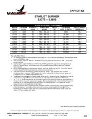
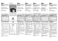
D. DIMENSIONSSee appropriate Dimension sheet for detailed dimensional information.Page 5<strong>SVG</strong>-9E. INSTALLATION1. Furnish an opening in the furnace shell 1/2" (13mm) larger than the burner tile outsidediameter. Since <strong>SVG</strong> burners can be fired in any position, they can be installed throughthe roof, walls, or bottom of the furnace.2. For installation in an existing hard or soft wall furnace (see Figure 1), make the hole in theinsulating material, where the burner tile will be installed, 3 to 6" (76 to 152mm) larger thanthe outside diameter of the tile.3. Wrap tile with two layers of 1" (25mm) fiber rated for a higher temperature than the furnace.Secure fiber wrap with tape or twine to compress the ceramic fiber wrap by 25% to retainthe fiber during installation. Pack additional fiber to fill any remaining openings completely.It is important to make sure the fiber is well packed around the burners firing tile or tube.Fiber must be repacked after the initial firing of the burner.W7390(NOT TO SCALE)Figure 1. Burner Installation
Page 6<strong>SVG</strong>-9E. INSTALLATION (Continued)4. For installations where it is desired to ram or cast refractory around the burner, allow 3 to 6"(76 to 152mm) larger diameter hole and pack as outlined in item 3.5. For air heater applications using <strong>SVG</strong>-MA, the alloy tube can extend into the furnace/oven.If the cross stream velocity over the alloy tube exceeds 1000 ft/min (305 m/min), a flameshield is required to prevent flame quenching; consult Hauck.6. The burner should be positioned so that the UV (ultraviolet) flame detector is located abovethe horizontal centerline to prevent moisture or airborne debris from settling into the scannerport and blocking the lens.NOTEIf the burner is operated in adverse conditions, Hauck recommendsinstalling a cooling/cleaning air line to the UV scanner. Typically, this can beaccomplished by installing a 1/2 NPT (DN 15) pipe tee between the UVscanner and the UV scanner connection on the burner backplate. Connect aclean air source of approximately 100 scfh (2.7 nm 3 /hr) to the pipe tee.Conditions such as preheated air, dirty combustion air, hot ambient air, orhigh moisture dictate this change.THE FLAME ROD AND SPARK IGNITER CONNECTIONS AREINTERCHANGEABLE, HOWEVER, DO NOT ATTEMPT TO IGNITE THE<strong>BURNER</strong> WITH THE FLAME ROD.7. If the integrated air differential pressure taps are to be used for air flow measurement, installa threaded pipe nipple into the air connection of the burner having a length that is at least4 times the pipe diameter. This will allow the use of the built-in differential air orifice taps foraccurate air flow measurement. For example, for 1-1/4 NPT (DN32) pipe use a pipe nipplethat is at least 5" (127mm) long.WARNINGAdjustment of this equipment by unqualified personnelcan result in fire, explosion, severe personal injury, oreven death.F. IGNITIONIgnition of the <strong>SVG</strong> is by a direct spark igniter (included). A 5000/6000 volt standard coil typeignition transformer or a half-wave “spark blind” solid state type transformer can be utilized. Bothtransformers yield satisfactory results, however, the standard coil type transformer providesreliable ignition over a wider range of air/fuel ratios than the half-wave type. For applicationsrequiring burner ignition with combustion air at or above 4 osi (1724 Pa), a standard coil ignitiontransformer must be used.
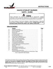
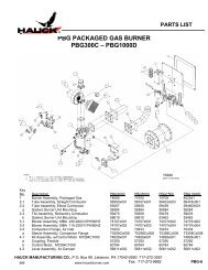
F. IGNITION (Continued)Page 7<strong>SVG</strong>-9X7391(NOT TO SCALE)Figure 2. Spark Igniter and Flame Rod Installation
F. IGNITION (Continued)Page 8<strong>SVG</strong>-9NOTEFor safety reasons, it is recommended that the burner beignited under low fire conditions.NOTELike all high velocity burners, the <strong>SVG</strong> will not ignite from ahot chamber.WARNINGIf standard coil ignition transformer is used, provisionsmust be made to eliminate the ignition spark falselysatisfying the “flame on” UV flame detector. Hauckdesigned flame supervisory panels accomplish this by“timing out” the spark transformer after a short (10seconds for most applications) trial for ignition.G. INITIAL SET-UP<strong>SVG</strong> burners typically operate with automatic control systems. The burners are capable ofproportional control over their entire capacity range. In a typical system, ignition will bepreceded by a series of steps.1. Once installed, the burner is ready for initial set-up. The specific operation of the burner willdepend on the individual system components in the entire combustion system. Refer to theinstruction sheets that accompany the individual components.2. Combustion air pressure should be set at the combustion air control valve. Typical settingswill be specific to the application. Hauck recommends that the combustion air setting remainat minimum until the burner has been ignited (refer to the burner capacities in theappropriate Supplemental Data Sheet for burner air flow at low fire conditions).3. Adjust the limiting gas orifice valve to the required opening (readjustment of the limiting gasorifice may be necessary for final burner set-up). Remove the screw cap and begin theadjustment; clockwise adjustment of the screw will decrease gas flow whilecounterclockwise adjustment will increase gas flow. Replace screw cap when theadjustment is complete.4. Refer to Section F for spark igniter set-up.5. Once the spark igniter is set and the initial gas and air adjustments are made, the burnercan be ignited. BE SURE THAT THE <strong>BURNER</strong> IS BEING IGNITED UNDER LOW FIRECONDITIONS (MINIMUM AIR AND <strong>GAS</strong> FLOWS). Ignite the burners. When all burners areignited, increase the combustion air to the high fire position (refer to burner capacities in theappropriate Supplemental Data Sheet for burner air flow at high fire conditions).
Page 9<strong>SVG</strong>-9G. INITIAL SET-UP (Continued)6. When the high fire combustion air is set, adjust the limiting gas orifice valve to achieve thedesired gas flow at high fire.7. Verify air/gas ratio using orifice meters in the air and gas lines. Static air pressure at theburner inlet can be related to air flows if an air orifice meter is not available.8. Drive the burner to the low fire position and verify that the settings are consistent. Repeatsteps 2 through 8 as necessary until high and low fire settings remain consistent.9. To shut down the burner system:A. Return the burner to the low fire position.B. Close all fuel shutoff valves.H. OPERATIONOnce properly installed, ignited and fired, the burner is ready for operation. The operation of theburner will depend on the specific items in the combustion control system and the application ofthe burners. Refer to the instruction sheet that accompanies each item. When the burner isfiring, the spark igniter should be shut off.I. MAINTENANCEThe <strong>SVG</strong> burners have no moving parts requiring any lubrication. However, periodic inspectionshould be performed to determine if cleaning is required and to inspect the condition of thecombustion tile or tube.Should it become necessary to remove the spark igniter for cleaning or inspection, the sparkigniter must be inserted properly for best ignition (see Figure 2 for proper spark igniterinstallation procedure).
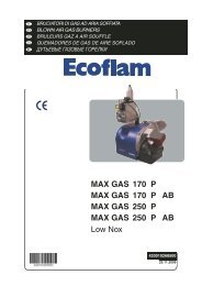
Page 10<strong>SVG</strong>-9I. MAINTENANCE (Continued)Should the combustor tube become damaged for the <strong>SVG</strong>-HC, it can be replaced as follows:Figure 3. Combustor Tube ReplacementX7392(NOT TO SCALE)1. Disconnect air and gas piping from burner, remove ignition wire from igniter, and remove UVscanner or wire from flame rod.2. Remove burner assembly (9) by removing nuts (11) and washers (10), and retain burnermounting gasket (8).3. Remove the retaining and jam nuts (6) and (7).4. For <strong>SVG</strong>-HC: Remove combustor tube retainer (5).5. Slide combustor tube (3) out of burner body (1).6. For <strong>SVG</strong>-HC: Discard combustor mounting gaskets (2) and (4).For <strong>SVG</strong>-HA: Retain combustor mounting gasket (2).7. For <strong>SVG</strong>-HC: Reassemble with new tube (3) and new gaskets (2) and (4).For <strong>SVG</strong>-HA: Reassemble with new tube (3) and retained gasket (2).8. Tighten retainer nuts (6) to specified torque and replace jam nuts (7).9. Install burner assembly mounting gasket (8) and burner assembly (9) with washers (10)and nuts (11).10. Repack fiber around combustor tile after burner assembly has been replaced (see Figure 1).J. RECOMMENDED SPARE PARTS LISTItem Qty. Part Number Description1 1 See Parts List Spark Igniter Assembly2 1 See Parts List Flame Rod Assembly (If Applicable)3 1 20579 UV Scanner (If Applicable)4 * See Parts List Replacement Tube Assembly (If Applicable)* - Quantity dependent upon number of burners installed; contact Hauck.Table 3. Recommended Spare Parts