RTG RADIANT TUBE GAS BURNERS
RTG RADIANT TUBE GAS BURNERS
RTG RADIANT TUBE GAS BURNERS

Create successful ePaper yourself
Turn your PDF publications into a flip-book with our unique Google optimized e-Paper software.
<strong>RTG</strong> <strong>RADIANT</strong> <strong>TUBE</strong> <strong>GAS</strong> <strong>BURNERS</strong>INSTRUCTIONSWARNINGThese instructions are intended for use only by experienced, qualifiedcombustion start-up personnel. Adjustment of this equipment and itscomponents by unqualified personnel can result in fire, explosion, severepersonal injury, or even death.TABLE OF CONTENTSSubjectPageA. General Information ……………………………………………………….…..….……. 2B. Receiving and Inspection ………………………………………….…….…...…….….. 2C. Capacities ………….……………………………………………………………………. 3D. Dimensions …………….………………………………………………………………... 5E. Installation ………….……………………………………………………………….…… 6F. Ignition …..…………………………………………..………………….…..….…….….. 9G. Initial Set-up ………………………………….…………………..……….…….………. 10H. Operation…………………………………………………………………………………. 11I. Maintenance …………………………………………………………………..………… 12J. Recommended Spare Parts List ……………………………………………………… 12These instructions are intended to serve as guidelines covering the installation, operation, and maintenance of Hauck equipment. Whileevery attempt has been made to ensure completeness, unforeseen or unspecified applications, details, and variations may precludecovering every possible contingency. WARNING: TO PREVENT THE POSSIBILITY OF SERIOUS BODILY INJURY, DO NOT USE OROPERATE ANY EQUIPMENT OR COMPONENT WITH ANY PARTS REMOVED OR ANY PARTS NOT APPROVED BY THEMANUFACTURER. Should further information be required or desired or should particular problems arise which are not coveredsufficiently for the purchaser's purpose, contact Hauck Mfg. Co.HAUCK MANUFACTURING CO., P.O. Box 90 Lebanon, PA 17042-0090 717-272-30511/07 www.hauckburner.com Fax: 717-273-9882<strong>RTG</strong>-9
Page 2<strong>RTG</strong>-9WARNINGThis equipment is potentially dangerous with the possibility of serious personal injuryand property damage. Hauck Manufacturing Company recommends the use of flamesupervisory equipment and fuel safety shutoff valves. Furthermore, Hauck urges rigidadherence to National Fire Protection Association (NFPA) standards and insuranceunderwriter’s requirements. Operation and regular preventative maintenance of thisequipment should be performed only by properly trained and qualified personnel.Annual review and upgrading of safety equipment is recommended.A. GENERAL INFORMATIONThe Hauck <strong>RTG</strong> Series Radiant Tube Burners provide improved flame stability and uniform heatdistribution in all types of radiant tube applications. Flame length and air/gas premix controlspermit adjusting the flame shape to match tube configuration precisely. The <strong>RTG</strong> SeriesBurners fire any clean industrial gas and will accommodate preheated air up to 700°F (371°C).Hauck Application Sheet GJ60 provides guidelines for installation and operation of <strong>RTG</strong> burnerson hot air applications.<strong>RTG</strong> burners typically operate with automatic control systems. The burners are capable ofproportional control over their entire capacity range. If the maximum firing rate does not allow ahigh turndown, low-high-off control may be more appropriate. Since the <strong>RTG</strong> burner can be setup for varying flame lengths and premix, the air requirements and heat inputs will vary with theapplication. Refer to Section C, Capacity Tables, for typical performance data.<strong>RTG</strong> burners can be spark ignited or will accommodate a premix gas pilot. The burners aredesigned to accommodate UV flame supervision, monitoring main flame with a single scanner.(A scanner adapter is required for preheated air operation). An air cooled flame rod is alsoavailable.B. RECEIVING AND INSPECTIONUpon receipt, check each item on the bill of lading and/or invoice to determine that allequipment has been received. A careful examination of all parts should be made to ascertain ifthere has been any damage in shipment.IMPORTANTIf the installation is delayed and the equipment isstored outside, provide adequate protection asdictated by climate and period of exposure. Specialcare should be given to all motors and bearings, ifapplicable, to protect them from rain or excessivemoisture.
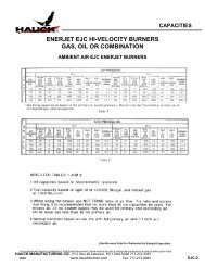
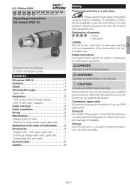
Page 3<strong>RTG</strong>-9C. BURNER CAPACITIES8 OSI 16 OSIMODEL NUMBERMODEL NUMBERSPECIFICATIONS 102 104 106 102 104 106LONGMax. Input @ 10% Excess Air (Btu/hr) 367,100 673,100 1,172,000 540,800 961,600 1,635,000Max. Air Flow (scfh) 3,800 6,980 12,140 5,600 9,960 16,940FL Min. Input @ Max. Air Flow (Btu/hr) 49,740 49,740 64,630 49,740 49,740 64,630AMEMax. Excess Air (%) 710 1,390 1,890 1,100 2,030 2,680SHORTMax. Input @ 10% Excess Air (Btu/hr) 540,800 901,600 1,521,000 739,300 1,310,000 2,134,000Max. Air Flow (scfh) 5,600 9,340 15,760 7,660 13,580 22,110F Min. Input @ Max. Air FlowL(Btu/hr) 89,440 149,100 200,800 89,440 149,100 200,800AM Max. Excess Air (%) 560 560 730 810 870 1,070ENOTES:1. Capacities based on natural gas with HHV of 1034 Btu/ft 3 , 0.59 S.G., and a stoichiometric air/gas ratio9.74:1 with burner firing into radiant tube.2. Air and gas flows based on 60°F @ sea level; capacities for preheated air will differ from those shown.3. Total air pressures measured 6 pipe diameters from burner air inlet.4. All data based on industry standard air and gas piping practices.5. Flame detection available via flame rod or UV scanner.Table 1. Burner Capacities
Page 4<strong>RTG</strong>-9C. BURNER CAPACITIES (Continued)3450 Pa 6900 PaMODEL NUMBERMODEL NUMBERSPECIFICATIONS 102 104 106 102 104 106LONGFLAMEMax. Input @ 10% Excess Air (kW) 97.1 178 310 143 254 432Max. Air Flow (nm 3 /hr) 102 187 325 150 267 454Min. Input @ Max. Air Flow (kW) 13.2 13.2 17.1 13.2 13.2 17.1Max. Excess Air (%) 710 1,390 1,890 1,100 2,030 2,680SHORTFLAMEMax. Input @ 10% Excess Air (kW) 143 238 402 196 346 564Max. Air Flow (nm 3 /hr) 150 250 422 205 364 592Min. Input @ Max. Air Flow (kW) 23.7 39.4 53.1 23.7 39.4 53.1Max. Excess Air (%) 560 560 730 810 870 1,070NOTES:1. Capacities based on natural gas with LHV of 36.74 MJ/nm 3 , 0.59 S.G., and a stoichiometric air/gasratio 9.74:1 with burner firing into radiant tube.2. Air and gas flows based on 0°C @ sea level; capacities for preheated air will differ from those shown.3. Total air pressures measured 6 pipe diameters from burner air inlet.4. All data based on industry standard air and gas piping practices.5. Flame detection available via flame rod or UV scanner.Table 2. Metric Burner Capacities
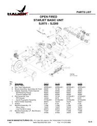
Page 5<strong>RTG</strong>-9D. DIMENSIONSY6090(NOT TO SCALE)Figure 1. Dimensions
D. DIMENSIONS (Continued)Page 6<strong>RTG</strong>-9Y6090 METRIC(NOT TO SCALE)Figure 2. Metric Dimensions
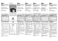
Page 7<strong>RTG</strong>-9E. INSTALLATION1. Typical mounting arrangements for the <strong>RTG</strong> burners are shown in Figure 3. The arrangementused will depend on the relationship between the backplate and the diameter of the tube.Figure 3. Three Typical Flange Mounting ArrangementsW197D2. The <strong>RTG</strong> burners must be properly centered in either the tube or an auxiliary air sleeve toensure that the ignition nozzle to tube or sleeve gap is properly maintained. There are threeadjusting screws (21) on the ignition nozzle (see Figure 4). These screws MUST be adjustedto EQUAL lengths so that the OD formed by the heads of the screws allows the burner toslide snugly into and against the ID of the tube or auxiliary air sleeve. To adjust the screws,loosen the locking nuts (22). After all screws have been properly adjusted, tighten the lockingnuts.3. When the actual tube ID exceeds the maximum recommended, an auxiliary air sleeve mustbe inserted into the tube. Substitutions should not be made since the area between theignition nozzle and the tube meters the flow of burner combustion air. If the tube ID exceedsthe maximum "I" dimension, the auxiliary sleeve must be specified on the order. Be sure theactual installation corresponds to the original specification.4. Prepare the end of the tube to accept the mounting bolts of the <strong>RTG</strong> burner backplate. Thearrangement used will depend on the relationship between the backplate and the diameter ofthe tube.5. Make sure that the burner gas and air inlets are properly aligned to meet the piping requirements.The gas inlet may be located in any position that will not obstruct the flame lengthcontrol screw or the observation ports. To rotate the gas inlet (refer to Figure 4):A. Loosen the spark igniter holding screw (31) and remove the spark igniter assembly (25)or (26).B. Loosen the body setscrew (23).C. Rotate the gas inlet assembly to the desired position.D. Tighten the body setscrew (23).E. Loosen the ignition nozzle setscrew (17).F. Rotate the nozzle assembly (20) until the locating collar realigns itself with the sparkigniter hole in the air body.G. Hand tighten the ignition nozzle setscrew (17).H. Replace the spark igniter (25) or (26). Adjust the nozzle collar until the igniter slipseasily into place.I. Ensure that the spark igniter tip is located 1/8" from the air/gas nozzle tip. (The igniterpipe will "bottom out" on the burner ignition cup).J. Tighten the setscrews (17 and 18).
Page 8<strong>RTG</strong>-9Y3243(NOT TO SCALE)Figure 4. Components6. Inset the <strong>RTG</strong> burner into the end of the tube and securely bolt it into place.7. Connect the fuel and air supply line to the appropriate connections on the burner and aircooled spark igniter.8. When UV flame scanning is used with an <strong>RTG</strong> burner in adverse conditions, i.e, preheated,dirty, hot ambient, or high moisture air, Hauck recommends the use of a UV scanner adapterassembly (34) which consists of 1/2 NPT (DN15) stainless steel pipe and heat block. Toinstall the assembly, accomplish the following:A. Remove pipe plug for optional UV scanner connection.B. Install UV scanner adapter assembly (34) into the vacant port. Ensure that heat block islocated between the UV scanner and the pipe nipple.C. Connect a clean, unheated air source to the 1/8 NPT (DN3) purge connection locatedon the heat block of approximately 100 scfh (2.7nm 3 /hr).D. Install the UV scanner (33) on to the UV scanner adapter assembly (34).
Page 9<strong>RTG</strong>-9WARNINGAdjustment of this equipment by unqualified personnelcan result in fire, explosion, severe personal injury, oreven death.F. IGNITIONIgnition of the <strong>RTG</strong> burner can be accomplished by a direct spark igniter or a premix gas pilot. A5000/6000 volt standard coil type ignition transformer or a half-wave "spark blind" solid statetype transformer can be utilized. Both transformers yield satisfactory results, however, thestandard coil type transformer provides reliable ignition over a wider range of air/fuel ratios thanthe half-wave type.1. The <strong>RTG</strong> burner typically incorporates an air cooled or non-air cooled spark igniter. Theigniter spark gap should be set at 1/8" (3mm) for reliable spark ignition. The air cooledspark igniter contains an orifice plate sized to allow proper cooling with an ambient airsupply of approximately 100 scfh (2.7nm 3 /hr) at pressure of 10-100 "wc (2.5 – 25 kPa);27.7 "wc (6.9 kPa). Installation of the spark igniter and adjustment of the spark gap isshown in Figure 5.Y7267(NOT TO SCALE)Figure 5. Air Cooled Spark Igniter Installation
2. For <strong>RTG</strong> burners utilizing a premix pilot spark igniter, accomplish the following:Page 10<strong>RTG</strong>-9A. Loosen the spark igniter holding screw (31).B. Insert the pilot into the burner and allow the pilot nozzle to "bottom out" on the burnerignition cup (20).C. Secure the spark igniter holding screw (31).D. Connect air/gas mixer to the inlet on the pilot.E. Connect ignition wire from ignition transformer to the spark plug on the spark igniter.G. INITIAL SET-UP<strong>RTG</strong> burners typically operate with automatic control systems. The burners are capable ofproportional control over their entire capacity range. In a typical system, ignition will bepreceded by a series of stepsNOTEFor safety reasons, it is recommended that the burner beignited under low fire conditions.WARNINGIf standard coil ignition transformer is used, provisionsmust be made to eliminate the ignition spark falselysatisfying the “flame on” UV sensor. Hauck designedflame supervisory panels accomplish this by “timingout” the spark transformer after a short (10 secondsfor most applications) trial for ignition.1. Once installed, the burner is ready for initial set-up. The specific operation of the burner willdepend on the individual system components in the entire combustion system. Refer to theinstruction sheets that accompany the individual components.2. Combustion air pressure should be set at the combustion air control valve. Typical settingswill be specific to the application. Hauck recommends that the combustion air settingsremain at minimum until the burner has been ignited (refer to the burner capacities in SectionC for burner air flows at low fire conditions).3. The flame length control screw (27) should be set at the midpoint of the adjustment. Loosenthe lock nut (28) and adjust the screw (27) until the slot in the screw head is at theappropriate position. (Readjustment of this screw may be necessary for final burner set-up).4. Premix adjustment of the burner should be initially set at 3 turns open. Loosen the premix nutsetscrew (24) and turn the premix nut (1) clockwise until it cannot be turned. Do not over turnpremix nut, or the premix roll pin can break. Next, turn the premix nut counter-clockwisethree turns then lock the setscrew. (Readjustment of this screw may be necessary for finalburner set-up).5. Adjust the limiting orifice valve, or Hauck LVG, in the gas line to the required opening.(Readjustment of the limiting orifice may be necessary for final burner set-up).
6. Refer to Section F for spark igniter set-up. Note: If utilizing premix pilot spark igniter, refer toHauck IPG-9 for detailed operating instructions.7. Once the spark igniter is set and the initial gas and air adjustments are made, the burner canbe ignited. BE SURE THAT THE BURNER IS BEING IGNITED UNDER LOW FIRECONDITIONS (MINIMUM <strong>GAS</strong> AND AIR FLOWS). Ignite the burner, or burners. When allburners are ignited, increase the combustion air to the high fire position (refer to burnercapacities in Section C for burner air flows at high fire conditions).8. Once the high fire combustion air is set, adjust the limiting gas orifice (step 5) to achievethe desired gas flow at high fire.9. Verify air/gas ratio using orifice meters in the air and gas lines.10. Flame length can be set to match the tube. Adjust the flame length control screw (26) toachieve the desired flame length. For most "U" tube applications, flame lengths that comeslightly beyond the firing leg of the tube are acceptable. If a helical stripe appears on thetube, shorten the flame length until the stripe disappears.11. Premix can be adjusted to improve flame stability and shape the flame. In some cases, thepremix adjustment will assist in removing "hot spots" on the tube. Counter-clockwise rotationof the premix nut (1) will increase the amount of air in the premix, while clockwise rotationwill decrease the amount of air in the premix. Typical adjustment range of premix is 2 to 4turns from fully closed, i.e., turn premix nut (1) clockwise until it can no longer be turned(closed position), then turn counter-clockwise 2 to 4 turns.12. Tighten the premix nut setscrew (24) and the flame length control screw lock nut (28).Page 11<strong>RTG</strong>-913. Drive the burner to the low fire position and verify that the settings are consistent. Repeatsteps 8 through 11 as necessary until high and low fire settings remain consistent and thedesired flame characteristics are achieved.14. To shut down the burner system:A. Return the burner to low fire position.B. Close all fuel shutoff valves.C. To prevent damage to the burner and other components, allow the furnace to cool tobelow 800°F before shutting off the combustion air.H. OPERATIONOnce properly installed, ignited and fired, the burner is ready for operation. The operation of theburner will depend on the specific items in the combustion control system and the application ofthe burners. Refer to the instruction sheet that accompanies each item. The burner should beignited at low fire conditions. When the burner is operating, the spark igniter or pilot can be shutoff since the burner is designed to maintain ignition of the air/gas mixture. In any case, ignitercooling air should remain on to assure optimum igniter service life.
Page 12<strong>RTG</strong>-9NOTEIf a loud, roaring noise occurs, it could be resonance. To eliminateresonance, first adjust the premix nut on the burner. If premix doesnot eliminate resonance, gradually restrict the exhaust outlet leg ofthe tube until the resonance is eliminated. This can be done with astainless steel plate. DO NOT ATTEMPT TO RESTRICT THE<strong>TUBE</strong> WHILE THE BURNER IS FIRING. Shut down the burner,place the restriction on the tube then resume firing the burner.NEVER COMPLETELY RESTRICT THE END OF THE <strong>TUBE</strong>.When minimum noise is reached, the steel plate can be welded tothe tube.I. MAINTENANCEThe <strong>RTG</strong> burner design and use of clean fuel gas, makes the system virtually maintenance free.For long life and optimum operation, however, it is recommended that the burner be periodicallyremoved for cleaning.Periodically check the air/gas ratio to ensure the burner is operating at peak efficiency. Flue gasanalysis can be performed with any commercially available flue gas analyzer.J. RECOMMENDED SPARE PARTS LISTItem Qty. Part Number Description1 1 See Parts List Air Cooled Spark Igniter Assembly (If Applicable)2 1 See Parts List Non-Air Cooled Spark Igniter Assembly (If Applicable)3 1 See Parts List Gas Pilot Assembly (If Applicable)4 1 20579 UV Scanner (If Applicable)5 1 See Parts List Flame Rod Assembly ( If Applicable)Table 3. Recommended Spare Parts