You also want an ePaper? Increase the reach of your titles
YUMPU automatically turns print PDFs into web optimized ePapers that Google loves.
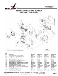
<strong>WHGP</strong> <strong>WALL</strong> <strong>HUGGER</strong> <strong>GAS</strong> <strong>BURNER</strong> <strong>PACKAGE</strong>INSTRUCTIONSWARNINGThese instructions are intended for use only byexperienced, qualified combustion start-uppersonnel. Adjustment of this equipment and itscomponents by unqualified personnel can result infire, explosion, severe personal injury, or evendeath.TABLE OF CONTENTSSubjectPageA. General Information………………………………………………………….…. 2B. Receiving & Inspection…………………………………………………………. 2C. Burner Capacity Table………………………………………………………….. 3D. Dimensions………………………………………………………………………. 5E. Installation…………………………………………………………………….…. 6F. Ignition……………………………………………………………………………. 7G. Initial Set-Up…………………………………………………………………….. 7H. Operation….……………………………………………………………………... 8I. Maintenance……………………………………………………………………... 8J. Recommended Spare Parts List………………………………………………. 8Appendix: Direct Spark Ignition Installation – W5987…………………….. 9Appendix: System Schematic Junction Box Wiring – V7460…………….. 10These instructions are intended to serve as guidelines covering the installation, operation, and maintenance of Hauck equipment. Whileevery attempt has been made to ensure completeness, unforeseen or unspecified applications, details, and variations may precludecovering every possible contingency. WARNING: TO PREVENT THE POSSIBILITY OF SERIOUS BODILY INJURY, DO NOT USE OROPERATE ANY EQUIPMENT OR COMPONENT WITH ANY PARTS REMOVED OR ANY PARTS NOT APPROVED BY THEMANUFACTURER. Should further information be required or desired or should particular problems arise which are not coveredsufficiently for the purchaser's purpose, contact Hauck Mfg. Co.HAUCK MANUFACTURING CO., P.O. Box 90 Lebanon, PA 17042-0090 717-272-30514/03www.hauckburner.com Fax: 717-273-9882<strong>WHGP</strong>-9
Page 2<strong>WHGP</strong>-9WARNINGThis equipment is potentially dangerous with the possibility of serious personal injuryand property damage. Hauck Manufacturing Company recommends the use of flamesupervisory equipment and fuel safety shutoff valves. Furthermore, Hauck urges rigidadherence to National Fire Protection Association (NFPA) standards and insuranceunderwriter’s requirements. Operation and regular preventative maintenance of thisequipment should be performed only by properly trained and qualified personnel.Annual review and upgrading of safety equipment is recommended.A. GENERAL INFORMATIONThe Hauck Wall Hugger Package (<strong>WHGP</strong>) Gas Burner is designed specifically for direct firedand single roof fired applications, the <strong>WHGP</strong> Package burner are pre-piped, pre-wired and skidmounted. The WHPG produces a flat flame for more even heating. The flame hugs the wall in acircular pattern, spreading out from the nozzle while the hot gasses move along the adjacentrefractory. Flame lengths are given in the capacity table in section C.B. RECEIVING AND INSPECTIONUpon receipt, check each item on the bill of lading and/or invoice to determine that allequipment has been received. A careful examination of all parts should be made to ascertain ifthere has been any damage in shipment.IMPORTANTIf the installation is delayed and the equipment isstored outside, provide adequate protection asdictated by climate and period of exposure. Specialcare should be given to all motors and bearings, ifapplicable, to protect them from rain or excessivemoisture.
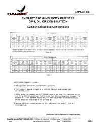
C. CAPACITESPage 3<strong>WHGP</strong>-9<strong>PACKAGE</strong> MODEL NUMBERSPECIFICATIONS 115 120 125 130HIGHFIREMax. Input @ 10% Excess Air (Btu/hr) 333,000 482,500 717,100 1,063,000Max. Air Flow @ 9.5 osig (scfh) 3,450 5,000 7,430 11,010Min. Input @ Max. Air Flow (Btu/hr) 76,300 100,200 207,600 285,100Max. Excess Air (%) 380 430 280 310Flame Length @ Max. Input (in.) 5 5 6 7Max. Input @ 10% Excess Air (Btu/hr)L108,100 177,500 232,500 340,700OW Air Flow @ 1 osig (scfh) 1,120 1,840 2,410 3,530FI Min. Input @ Air Flow (Btu/hr) 26,680 32,050 75,270 76,510RE Max. Excess Air (%) 345 510 240 390NOTES:1. Capacities based on natural gas with HHV of 1034 Btu/ft 3 , 0.59 S.G., and a stoichiometricair/gas ratio of 9.74:1 with burner firing into chamber under no pressure.2. Air and gas flows based on 60°F @ sea level.3. Static air pressures measured at the burner air inlet pressure tap.4. Flame lengths measured from the end of the refractory tile.5. All data based on industry standard air and gas piping practices.6. Flame detection available via flame rod or UV scanner.7. Max. air flow based on blower motor operation @ 75 Hz.Table 1. Burner Capacites
C. CAPACITES (Continued)Page 4<strong>WHGP</strong>-9<strong>PACKAGE</strong> MODEL NUMBERSPECIFICATIONS 115 120 125 130HIGHFIREMax. Input @ 10% Excess Air (kW) 88.0 128 190 281Max. Air Flow @ 4,095 Pa (nm 3 /hr) 92.4 134 199 295Min. Input @ Max. Air Flow (kW) 20.2 26.5 54.9 75.4Max. Excess Air (%) 380 430 280 310Flame Length @ Max. Input (mm) 125 125 150 175Max. Input @ 10% Excess Air (kW)L28.6 47.0 61.5 90.0OW Air Flow @ 430 Pa (nm 3 /hr) 30.0 49.3 64.6 94.5FI Min. Input @ Air Flow (kW) 7.1 8.5 19.9 20.2RE Max. Excess Air (%) 345 510 240 390NOTES:1. Capacities based on natural gas with LHV of 36.74 MJ/nm 3 , 0.59 S.G., and a stoichiometricair/gas ratio of 9.74:1 with burner firing into chamber under no pressure.2. Air and gas flows based on 0°C @ sea level.3. Static air pressures measured at the burner air inlet pressure tap.4. Flame lengths measured from the end of the refractory tile.5. All data based on industry standard air and gas piping practices.6. Flame detection available via flame rod or UV scanner.7. Max. air flow based on blower motor operation @ 75 Hz.Table 2. Metric Burner Capacites
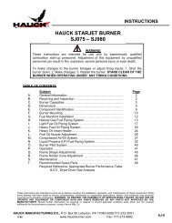
D. DIMENSIONSPage 5<strong>WHGP</strong>-9Y7338(NOT TO SCALE0Figure 1. Dimensions
Page 6<strong>WHGP</strong>-9E. INSTALLATION1. Furnish an opening in the furnace wall slightly larger than the outside dimensions of therefractory tile. Since <strong>WHGP</strong> burners can fire in any position, they can be installed throughthe roof, walls or bottom of the furnace.CAUTIONDo not disassemble the tile from the burner wheninstalling the burner. A bonding agent seals theburner to the tile. Disassembly will destroy theeffectiveness of the seal.2. Fabricate four angle mounting clips or brackets and bolt them to the four corners of themounting plate as shown in the drawings on page 4.3. Pack Fiberfrax, or other suitable insulating rope, in the entire grooved section of the tile.This will provide a seal between the burner tile and the furnace refractory and firebrick.4. Coat the outside surfaces of the burner tile with fire clay.5. Insert the tile into the furnace opening. The outlet end of the tile must be flush withthe inner furnace wall surface. If the furnace wall is too thick, or too thin, the burnermust be recessed or extended with spacers to meet this requirement. The furnace wallshould be flat in the vicinity of the <strong>WHGP</strong> tile to permit free expansion of the hotcombustion gasses.6. Bolt the burner mounting plate to the furnace wall.7. Ensure that a complete seal has been made between the mounting plate, burner tile andfurnace wall.8. Install the air and gas lines at the appropriate connections. Air and gas pressures will bedetermined by the application and specific capacity requirements of the equipment.Consult Hauck Manufacturing for piping recommendations. Hauck FPN Flexible PipeNipples are recommended to alleviate vibrations and thermal expansion of pipeconnections.9. Insert the gas pilot or spark igniter into the appropriate connection (Ignition method will bedetermined upon ordering the burner). See section F, ignition, for pilot set-up or sparkigniter installation.10. Verify that all piping connections are tight. Close all port openings on the burnerbackplate. If port openings are left open, the burner mounting plate will overheat.
F. IGNITIONPage 7<strong>WHGP</strong>-9WARNINGAdjustment of this equipment, by unqualifiedpersonnel, can result in fire, explosion, severepersonal injury, or even death.<strong>WHGP</strong> burners can be spark ignited or gas pilot ignited.For spark ignited burners:1. The burner will come with the igniter installed. The igniter threads into the gas inlet teeand will bottom out at the end of the burner gas nozzle. Spark gap should be set at 3/32"as shown in drawing CW5987.2. Provide a high voltage ignition wire to the spark igniter.3. Upon energizing the ignition transformer, the igniter should spark across the gap.4. Ignite the burner under low fire conditions.For gas pilot ignited burners:1. See pilot vendor literature.a) Be sure that the pilot threads tightly into pilot port.b) Connect air & gas lines to the pilot.c) Connect ignition wire to pilot.d) Attempt pilot ignition.2. For Hauck IPG pilots:See Hauck Sheet IPG-9a) Be sure that the pilot threads tightly into the pilot port.b) Follow instructions in IPG-9.G. INITIAL SET-UP<strong>WHGP</strong> burners typically operate with automatic control systems. The burners are capable ofproportional control over their entire capacity range. In a typical system, ignition will bepreceded by a series of steps.1. Once installed, the burner is ready for initial set-up. The specific operation of the burnerwill depend on the individual system components in the entire combustion system. Referto the Instruction Sheets that accompany the individual components.2. Combustion air pressure should be set at the combustion air control valve. Typicalsettings will be specific to the application. Hauck recommends that the combustion airsetting remain at minimum until the burner has been ignited. Refer to the capacity table inSection C for burner air flows at various combustion air pressures.3. Adjust the limiting orifice valve, or Hauck LVG, in the gas line to the required opening.(Readjustment of the limiting orifice may be necessary for final burner set-up)4. Refer to Section F for spark igniter and pilot set-up.
Page 8<strong>WHGP</strong>-95. Once the pilot or spark igniter have been set-up, the burner is ready for ignition. BESURE THAT THE <strong>BURNER</strong> IS BEING IGNITED UNDER LOW FIRE CONDITIONS(MINIMUM <strong>GAS</strong> AND AIR FLOWS.) Ignite the burner, or burners. When all burners areignited, bring the combustion air to the high fire position.6. Once the high fire combustion air is set, adjust the limiting gas orifice (Step 3) to achievethe desired gas flow at high fire.7. Verify air/gas ratio using orifice meters in the air and gas lines.8. Run the burner to low fire position and verify that settings are consistent.9. To shut down the burner system:a. Return the burner to the low fire position.b. Close all fuel shutoff valvesc. To prevent damage to the burner and other components, allow thefurnace to cool to below 600 o F before shutting off the combustion air.H. OPERATIONOnce installed, ignited and fired, the burner is ready for operation. The operation of the burnerwill depend on the specific items in the combustion control system. Refer to the instruction sheetthat accompanies each item. When the burner is firing, the gas pilot or spark igniter should beshut off.I. MAINTENANCEThe <strong>WHGP</strong> burner consists of a minimum number of parts. No metal parts extend into theradiant heat of the refractory tile. Large, concentric discharge ports in the gas and air nozzleseliminate blockage. Maintenance is limited to periodically cleaning the pilot nozzle and flamedetector.Periodically check the air/gas ratio to ensure the burner is operating at peak efficiency. Flue gasanalysis can be performed with the Hauck FGA flue gas analyzer.J. RECOMMENDED SPARE PARTS LISTItem Qty. Part Number DescriptionTable 3. Recommended Spare Parts
APPENDIX:Page 9<strong>WHGP</strong>-9
APPENDIX:Page 10<strong>WHGP</strong>-9V7460
Page 11<strong>WHGP</strong>-9
Page 12<strong>WHGP</strong>-9
Page 13<strong>WHGP</strong>-9