Butterfly valves DKR
Butterfly valves DKR
Butterfly valves DKR

Create successful ePaper yourself
Turn your PDF publications into a flip-book with our unique Google optimized e-Paper software.
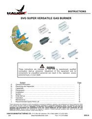
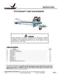
<strong>Butterfly</strong> <strong>valves</strong> <strong>DKR</strong>Technical Information · GB3.1.6.8 Edition 08.09• For hot air and flue gas• Low leakage rates ensure high product quality• Suitable for high burner capacities due to large nominaldiameters• Simple installation thanks to clamping betweenstandard flanges• Low-maintenance operation• Robust design for a long service lifewww.kromschroeder.com
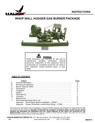
Application4<strong>Butterfly</strong> valve <strong>DKR</strong>..F with gear motor GT 50 Roller hearth kiln in the ceramics industry Forging furnace<strong>DKR</strong> · Edition 08.09
Application51.1 Examples of application1.1.1 Adjusting the high-fire rate<strong>Butterfly</strong> valve <strong>DKR</strong>..H with manual adjustment is used to adjustthe high-fire rate.VAGMGT 50 + <strong>DKR</strong>..F<strong>DKR</strong>..H1.1.2 Adusting the burner outputIn pneumatic ratio control systems the butterfly valve withmounted gear motor GT 50..E determines the air volume forthe required burner output.<strong>Butterfly</strong> valve <strong>DKR</strong>..H with manual adjustment is used to adjustthe high-fire rate.VAG4 – 20 mAMGT 50..E + <strong>DKR</strong><strong>DKR</strong>..H<strong>DKR</strong> · Edition 08.09
Application > Examples of application61.1.3 Hot air compensation<strong>Butterfly</strong> valve <strong>DKR</strong> is used on burners that are operated withpreheated combustion air at temperatures of up to 650°C.GIKWPSV AG +V AS 1MTwo-PointGT 50 + <strong>DKR</strong><strong>DKR</strong> · Edition 08.09
2 FunctionThe butterfly valve is designed on the basis of the free-flowprinciple (no deflection of the flow). It releases a cross-sectionfor the flowing medium, depending on a rotary movementbetween 0 and 90°.<strong>Butterfly</strong> valve <strong>DKR</strong>..D is with disc clearance; butterfly valve<strong>DKR</strong>..A is equipped with a mechanical stop bar.7R90<strong>DKR</strong> · Edition 08.09
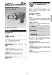
83 Flow rate∆p [mbar]10080605040<strong>DKR</strong> 15,<strong>DKR</strong> 20,<strong>DKR</strong> 25<strong>DKR</strong> 32<strong>DKR</strong> 40<strong>DKR</strong> 50<strong>DKR</strong> 65<strong>DKR</strong> 80<strong>DKR</strong> 15<strong>DKR</strong> 20<strong>DKR</strong> 25<strong>DKR</strong> 32<strong>DKR</strong> 40<strong>DKR</strong> 50<strong>DKR</strong> 65<strong>DKR</strong> 803020108P16543210,1 0,2 0,30,51 2 3 4 5 6 7 8 10 20 30 50 100 200 300 500 1000 2000 3000V' air [m3/h (n)]3.1 <strong>DKR</strong> 15 – 80The characteristic curves are measured at 15°C with a measurementset-up in accordance with the standards EN 13611/EN 161.This involves measuring the pressure 5 x DN upstream anddownstream of the unit under test. The pressure drop of thepipe is also measured but is not compensated for.Left curve:Leakage volume at a 0° opening angle.Right curve:Max. flow rate at a 90° opening angle.<strong>DKR</strong> · Edition 08.09
Flow rate9∆p [mbar]10080605040<strong>DKR</strong> 100<strong>DKR</strong> 125<strong>DKR</strong> 150<strong>DKR</strong> 200<strong>DKR</strong> 250<strong>DKR</strong> 300<strong>DKR</strong> 350<strong>DKR</strong> 450<strong>DKR</strong> 500<strong>DKR</strong> 400<strong>DKR</strong> 100<strong>DKR</strong> 125<strong>DKR</strong> 150<strong>DKR</strong> 200<strong>DKR</strong> 300<strong>DKR</strong> 350<strong>DKR</strong> 400<strong>DKR</strong> 450<strong>DKR</strong> 250<strong>DKR</strong> 50030201086543211 2 3 4 5 6 7 8 10 20 30 50 100 200 300 500 1000 2000 5000 10000 20000 40000 100000 200000V' air [m3/h (n)]3.2 <strong>DKR</strong> 100 – 500The characteristic curves are measured at 15°C with a measurementset-up in accordance with the standards EN 13611/EN 161.This involves measuring the pressure 5 x DN upstream anddownstream of the unit under test. The pressure drop of thepipe is also measured but is not compensated for.Left curve:Leakage volume at a 0° opening angle.Right curve:Max. flow rate at a 90° opening angle.<strong>DKR</strong> · Edition 08.09
Flow rate103.3 Interactive calculation of the nominal size∆p [mbar]10080605040<strong>DKR</strong> 15,<strong>DKR</strong> 20,<strong>DKR</strong> 25<strong>DKR</strong> 32<strong>DKR</strong> 40<strong>DKR</strong> 50<strong>DKR</strong> 65<strong>DKR</strong> 80<strong>DKR</strong> 100<strong>DKR</strong> 125<strong>DKR</strong> 15<strong>DKR</strong> 150<strong>DKR</strong> 200<strong>DKR</strong> 250<strong>DKR</strong> 20<strong>DKR</strong> 300<strong>DKR</strong> 350<strong>DKR</strong> 400<strong>DKR</strong> 25<strong>DKR</strong> 450<strong>DKR</strong> 500<strong>DKR</strong> 32<strong>DKR</strong> 40<strong>DKR</strong> 50<strong>DKR</strong> 65<strong>DKR</strong> 80<strong>DKR</strong> 100<strong>DKR</strong> 125<strong>DKR</strong> 150<strong>DKR</strong> 200<strong>DKR</strong> 300<strong>DKR</strong> 350<strong>DKR</strong> 400<strong>DKR</strong> 450<strong>DKR</strong> 250<strong>DKR</strong> 50030201086543210,1 0,2 0,30,51 2 3 4 5 6 7 8 10 20 30 40 5060 80100 200 300400 600 1000 2000 40006000 10000 20000 40000 100000 200000V' air [m3/h (n)]DensityFlow rate V· (standard)Outlet pressure p a∆p max.Medium temperatureProduct ∆p a vFlow rate V· (operation)<strong>DKR</strong> · Edition 08.09
Flow rate3.4 Determining the nominal sizeDetermining the size of a butterfly valve using the valve authoritya for normal operation, see – [Glossary – p. 28].A valve authority of a = 0.3 provides good control properties.Select the required nominal size from the flow rate diagramon the basis of the desired flow rate V· and the calculated ∆p.ExampleWe want to find the nominal size of the butterfly valve <strong>DKR</strong> forair to be used for modulating control of a gas burner:Outlet pressure: p a = 30 mbarAir flow rate: V· = 900 m 3 /h (n)Valve authority: a = 0.3The flow velocity in the pipes exercises a considerable influenceon the pressure loss and the noise development. Whendesigning the butterfly valve, it is recommended that the flowvelocity of 30 m/s is not exceeded. A flow rate V· = 900 m 3 /h (n)results in a pipe of DN 100, see – [Flow velocities in pipes – p. 17].In order to obtain the pressure loss ∆p = 13 mbar that has beencalculated using the valve authority, valve <strong>DKR</strong> 80 is selectedfrom the flow rate diagram, see P1 – [<strong>DKR</strong> 15 – 80 – p. 8]If pipe fittings (reducing fittings) are installed in the pipework,the additional pressure loss must be taken into account.11V' [%]100a = 0.3a < 0.3a > 0.3<strong>DKR</strong>a × p∆p a100%=1 – a00 90a = ∆p 100% /p e[°]∆p 100% = 0.3 × 30 mbar = 12.9 mbar = 13 mbar1 - 0.3<strong>DKR</strong> · Edition 08.09
Flow rate133.6 Calculation formulaek V value.Vk v = (n)514·Flow rateρ (n)· T∆p · p aV . (n) = k V· 514·∆p · p aρ (n) · TPressure loss∆p = r (n) × T V·×p a(k V × 514Valve authoritya = ∆p 100%p eLegendV· (n) [m 3 /h] Standard volumetric flow rater (n)[kg/m 3 ] Gas density in standard state) 2∆p [bar] Pressure loss via control elementp a [bar]Absolute pressure downstream of the controlelementp e [bar] Inlet pressureT [K] Absolute temperature of the mediuma – Valve authority<strong>DKR</strong> · Edition 08.09
Flow rate143.7 k V valuesOpening angle0° 90°<strong>DKR</strong> 15 0.11 4.0<strong>DKR</strong> 20 0.11 9.2<strong>DKR</strong> 25 0.11 12.6<strong>DKR</strong> 32 0.18 32<strong>DKR</strong> 40 0.32 62<strong>DKR</strong> 50 0.63 115<strong>DKR</strong> 65 0.92 195<strong>DKR</strong> 80 1.3 287<strong>DKR</strong> 100 2 494<strong>DKR</strong> 125 2.3 804<strong>DKR</strong> 150 2.8 1260<strong>DKR</strong> 200 5 2060<strong>DKR</strong> 250 8 3450<strong>DKR</strong> 300 11 4820<strong>DKR</strong> 350 15 6420<strong>DKR</strong> 400 20 8600<strong>DKR</strong> 450 24 10800<strong>DKR</strong> 500 31 13700<strong>DKR</strong> · Edition 08.09
154 Selection15 20 25 32 40 50 65 80 100 125 150 200 250 300 350 400 450 500 Z 03 H F 100 350 450 650 D A<strong>DKR</strong> ● ● ● ● ● ● ● ● ● ● ● ● ● ● ● ● ● ● ● ● ● ● ● ● ● ● ● = standard, = availableOrder example<strong>DKR</strong> 250Z03F650D4.1 Type codeCodeDescription<strong>DKR</strong>Butterfl y valve for air and fl ue gas15–500 Nominal diameterZFor fi tting between two DIN fl anges03 p e max. 300 mbarHWith manual adjustmentFWith free shaft endMax. medium temperature [°C]:100350450650100350450650DAWith disc clearanceWith stop bar<strong>DKR</strong> · Edition 08.09
165 Project planning information5.1 InstallationThe butterfly valve must be installed in-between two flangesin accordance with EN 1092, PN 16.The length of the inlet and outlet section should be 5 x DN.For the design of the pipe, it is advisable not to exceed a flowvelocity of 30 m/s, see – [Flow velocities in pipes – p. 17].In conjunction with the butterfly valve <strong>DKR</strong>, the actuator can beused for hot air of up to 250°C. When using the attachment setwith heat deflector, the actuator can be used in temperaturesof up to 650°C.<strong>Butterfly</strong> valve <strong>DKR</strong> and gear motor GT 50 are supplied separatelyor assembled.Installation positionThe unit can be installed in any position.MDN ≥ 200M<strong>DKR</strong>..AFor butterfly <strong>valves</strong> <strong>DKR</strong> with a nominal size of DN ≥ 200, werecommend installing the acutator in a vertical pipe. For butterfly<strong>valves</strong> with stop bars (<strong>DKR</strong>..A), we recommend installingthem in a vertical pipe and selecting the direction of flow frombottom to top in order to prevent dirt accumulating on the stopbar and to ensure that the valve closes tightly.If the valve is used with hot air, the pipe should be adequatelyinsulated so as to reduce the ambient temperature. The flangesand the butterfly valve <strong>DKR</strong> must be kept free of insulatingmaterial. Install the butterfly valve in such a way that rising hotair does not circulate around the actuator, using the optionalattachment set with heat deflector, if required, see – [Heatdeflector – p. 23].<strong>DKR</strong> · Edition 08.09
Project planning information17Flow velocityv [ft/min]20000160001200010000800060004000v [m/s]100806050403020DN 6 (7)DN 8 (9.9)DN 10 (13.6)DN 15 (17.3)DN 20 (22.3)DN 25 (28.5)DN 32 (37.2)DN 40 (43.1)DN 50 (54.5)DN 65 (70.3)DN 80 (82.5)DN 100 (107.1)DN 125 (131.7)DN 150 (159.3)DN 200 (206,5)DN 250 (260.4)DN 300 (309.7)DN 350 (339.6)DN 400 (389.2)DN 450 (437)DN 500 (486)20001016008120010006580046003400220011 2 3 4 5 6 7 8 10 20 30 40 50 60 80 100 200 300 400 600 8001000 2000 3000 6000 1000020000V' [m 3 /h]40 50 60 80 100 200 300 400 500 700 1000 2000 3000 5000 7000 10000 20000 30000 50000 100000 200000Flow rateV' [SCFH]5.2 Flow velocities in pipesIt is recommended that flow velocities of 30 m/s are not exceededwhen using the valve on thermoprocessing equipment.The details on the internal diameter correspond to the conventionaldimensions for gas pipes as stipulated in the standardEN 10220. Different cross-sections will result in flow velocitiesthat differ correspondingly.<strong>DKR</strong> · Edition 08.09
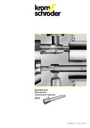
Project planning information∆p [mbar]GT 50-07GT 50-15GT 50-30 to GT 50-24010090807060504030201000DN 125DN 150DN 200DN 250DN 300DN 350DN 400DN 450DN 5005 10 15 20 25Torque [Nm]5.3 Actuator running time<strong>Butterfly</strong> valve <strong>DKR</strong> is controlled by gear motor GT 50. Theshortest actuator running time per 90° depends on the requiredtorque.The characteristic curves relate to the maximum torque producedby the flow rate. In general, maximum torque is reachedat approx. 70°.Example:For butterfly <strong>valves</strong> <strong>DKR</strong> 125 or <strong>DKR</strong> 150, any running timecould be used.The running time is reduced by a factor of 0.83 at a frequencyof 60 Hz on the actuator.18<strong>DKR</strong> · Edition 08.09
196 Accessories6.1 Attachment set with linkageWith linkageWith linkage, for fitting a gear motor GT 50 to a butterfly valve <strong>DKR</strong>..D. Fitted orenclosed as an additional item on delivery.For nominal sizes Order No. WeightEnclosed Fitted [kg]DN 15 – 20 26501300 26502000 1.5DN 25 – 50 26501310 26502010 1.6DN 65 – 100 26501320 26502020 1.7DN 125 26501330 26502030 1.9DN 150 – 200 26501340 26502040 1.9DN 250 26501350 26502050 2.2DN 300 26501360 26502060 2.2DN 350 26501370 26502070 2.4DN 400 26501380 26502080 2.5DN 450 – 500 26501390 26502090 2.6With linkage and shock suppressorWith linkage and shock suppressor, for fitting a gear motor GT 50 to a butterfly valve<strong>DKR</strong>..A. Fitted or enclosed as an additional item on delivery.For nominal sizes Order No. WeightEnclosed Fitted [kg]DN 15 – 20 26502350 26501400 1.6DN 25 – 50 26502360 26501410 1.8DN 65 – 100 26502370 26501420 1.9DN 125 26502380 26501430 2.1DN 150 – 200 26502390 26501440 2.1DN 250 26502400 26501450 2.4DN 300 26502410 26501460 2.4DN 350 26502420 26501470 2.6DN 400 26502430 26501480 2.7DN 450 – 500 26502440 26501490 2.8<strong>DKR</strong> · Edition 08.09
Accessories > Attachment set with linkage206.1.1 DimensionsFH1CE263 mm<strong>DKR</strong> nominal sizeDimensions [mm]C E F H1DN 15, DN 20 194 285 35 60DN 25 194 285 35 75DN 32 194 285 35 80DN 40 194 285 35 83DN 50 194 285 35 85DN 65 194 285 35 95DN 80 194 285 35 105DN 100 194 285 35 115DN 125 239 330 35 135DN 150 239 330 35 150DN 200 239 330 35 175DN 250 294 395 45 220DN 300 294 395 45 240DN 350 319 435 60 290DN 400 350 465 60 335DN 450 380 495 60 360DN 500 380 495 60 400<strong>DKR</strong> · Edition 08.09
6.2 Attachment set for axial actuatorFor axial attachment of a gear motor GT 50 to a butterfly valve <strong>DKR</strong>..A. Fitted orenclosed as an additional item on delivery.For nominal sizes Order No. WeightEnclosed Fitted [kg]DN 15 – 20 26502150 26502600 1.3DN 25 – 50 26502160 26502610 1.3DN 65 – 100 26502170 26502620 1.3DN 125 26502180 26502630 1.3DN 150 – 200 26502190 26502640 1.3DN 250 26502200 26502650 1.3DN 300 26502210 26502660 1.4DN 350 26502220 26502670 1.4DN 400 26502230 26502680 1.4DN 450 – 500 26502240 26502690 1.421<strong>DKR</strong> · Edition 08.09
Accessories > Attachment set for axial actuator226.2.1 DimensionsF148 mm122 mm195 mmH1 100 mm<strong>DKR</strong> nominal sizeDimensionsFH1DN 15, DN 20 35 60DN 25 35 75DN 32 35 80DN 40 35 83DN 50 35 85DN 65 35 95DN 80 35 105DN 100 35 115DN 125 35 135DN 150 35 150DN 200 35 175DN 250 45 220DN 300 45 240DN 350 60 290DN 400 60 335DN 450 60 360DN 500 60 400<strong>DKR</strong> · Edition 08.09
Accessories236.3 Heat deflectorRecommended for operation with hot air ≥ 250°C in conjunctionwith the attachment set with linkage to protect the gearmotor GT 50. The ambient temperature on the gear motormust not exceed 60°C.CB63.594G200 mmAHeat deflector on <strong>DKR</strong> with attachment set and gear motor GT 50<strong>DKR</strong> nominal sizeDimensions [mm]ABDN 15 – DN 100 366 70DN 125 – DN 200 459 127DN 250, DN 300 566 180DN 350 619 207DN 400 673 230DN 450, DN 500 758 285Order number: 74921670<strong>DKR</strong> · Edition 08.09
247 Technical dataGas type: air, flue gas.Housing material: cast steel, heat-resistant cast iron,valve disc: steel, cast steel, heat-resistant cast iron,drive shaft: stainless steel,seals: free of asbestos.Inlet pressure p e : max. 300 mbar.Medium temperature: -20 to +100°C, +350°C, +450°C,+650°C,ambient temperature: -20 to +60°C.<strong>DKR</strong> · Edition 08.09
1Technical data257.1 DimensionsB<strong>DKR</strong>..H0234567FDND8GH1H27.1.1 <strong>DKR</strong>..HType DN H1 H2 D B G F Weightmm mm mm mm mm mm kg<strong>DKR</strong> 15..H 15 60 125 44 25 105 100 1.14<strong>DKR</strong> 20..H 20 60 125 44 25 105 100 1.14<strong>DKR</strong> 25..H 25 75 140 60 25 105 100 1.14<strong>DKR</strong> 32..H 32 80 145 67 25 105 100 1.4<strong>DKR</strong> 40..H 40 83 148 75 25 105 100 1.5<strong>DKR</strong> 50..H 50 85 150 85 25 105 100 1.6<strong>DKR</strong> 65..H 65 95 160 105 25 120 100 2.2<strong>DKR</strong> 80..H 80 105 170 120 30 120 100 2.5<strong>DKR</strong> 100..H 100 115 180 140 30 120 100 2.8<strong>DKR</strong> 125..H B 125 135 205 170 35 150 115 5.0<strong>DKR</strong> 150..H 150 150 220 195 40 150 115 6.3<strong>DKR</strong> 200..H 200 175 245 255 40 150 115 9.3<strong>DKR</strong> 250..H 250 220 305 310 40 150 115 13.9<strong>DKR</strong> 300..H 300 240 325 360 45 220 160 22.6<strong>DKR</strong> 350..H 350 290 410 415 45 220 160 27<strong>DKR</strong> 400..H 400 335 455 365 50 220 160 39<strong>DKR</strong> 450..H 450 360 480 520 50 220 160 45<strong>DKR</strong> 500..H 500 400 520 620 55 220 160 56<strong>DKR</strong> · Edition 08.09
Technical data > Dimensions267.1.2 <strong>DKR</strong>..FType DN H1 H2 D B d d1 Weightmm mm mm mm mm mm kg<strong>DKR</strong> 15..F 15 60 75 44 25 8 8 1.14<strong>DKR</strong> 20..F 20 60 75 44 25 8 8 1.14<strong>DKR</strong> 25..F 25 75 75 60 25 8 10 1.14<strong>DKR</strong> 32..F 32 80 75 67 25 8 10 1.4<strong>DKR</strong> 40..F 40 83 75 75 25 8 10 1.5<strong>DKR</strong> 50..F 50 85 75 85 25 8 10 1.6<strong>DKR</strong> 65..F 65 95 75 105 25 12 12 2.2<strong>DKR</strong> 80..F 80 105 75 120 30 12 12 2.5<strong>DKR</strong> 100..F 100 115 75 140 30 12 12 2.8<strong>DKR</strong> 125..F 125 135 75 170 35 12 12 5.0<strong>DKR</strong> 150..F 150 150 75 195 40 12 12 6.3<strong>DKR</strong> 200..F 200 175 75 255 40 12 15 9.3<strong>DKR</strong> 250..F 250 220 75 310 40 12 15 14<strong>DKR</strong> 300..F 300 240 75 360 45 12 20 23<strong>DKR</strong> 350..F 350 290 75 415 45 12 25 27<strong>DKR</strong> 400..F 400 335 75 365 50 12 30 39<strong>DKR</strong> 450..F 450 360 75 520 50 12 30 45<strong>DKR</strong> 500..F 500 400 75 620 55 12 30 56<strong>DKR</strong>..F∅ d1 ∅ dDNDR90H2H1B<strong>DKR</strong> · Edition 08.09
278 Maintenance cycles<strong>Butterfly</strong> valve <strong>DKR</strong> requires little servicing.We recommend a function check once a year.<strong>DKR</strong> · Edition 08.09
289 GlossaryControl characteristic, valve authorityIn order for the butterfly valve to be able to influence the flowrate, a proportion of the pressure loss ∆p from the entire systemhas to be caused by the butterfly valve. Since the overallpressure loss ∆p should be kept to a minimum, a valve authoritya = 0.3 is recommended for the butterfly valve. This meansthat of the overall pressure loss ∆p there is a 30% drop on thefully open butterfly valve.Hot air compensationThe volume of air increases with the addition of hot air. Theoxygen content contained in the air decreases with every m 3 .In order to maintain a constant oxygen content, additional airhas to be added to the combustion gas.<strong>DKR</strong> · Edition 08.09
FeedbackFinally, we are offering you the opportunity to assess this “Technical Information (TI)” and to give us your opinion, so that wecan improve our documents further and suit them to your needs.ClarityFound information quicklySearched for a long timeDidn’t find informationWhat is missing?No answerComprehensionCoherentToo complicatedNo answerScopeToo littleSufficientToo wideNo answer29UseTo get to know the productTo choose a productPlanningTo look for informationNavigationI can find my way aroundI got “lost”No answerMy scope of functionsTechnical departmentSalesNo answerRemarks(Adobe Reader 7 or higher required)ContactElster GmbHPostfach 2809 · 49018 OsnabrückStrotheweg 1 · 49504 Lotte (Büren)GermanyT +49 541 1214-0F +49 541 1214-370info@kromschroeder.comwww.kromschroeder.comwww.elster.comThe current addresses of our internationalagents are available on the Internet:www.kromschroeder.com SalesKromschröder, a productbrand of the Elster GroupWe reserve the right to make technicalmodifications in the interests of progress.Copyright © 2007 Elster GroupAll rights reserved.03250551<strong>DKR</strong> · Edition 08.09