en18.Never direct discharge at bystanders or allow anyone in front of the unit.19.Never leave a running unit unattended. Always disengage the auger andtraction controls, stop engine, and remove keys.20.Do not operate the unit while under the influence of alcohol or drugs.21.Keep in mind the operator is responsible for accidents occurring to otherpeople or property.22.Data indicates that operators, age 60 years and above, are involved in alarge percentage of power equipment−related injuries. These operatorsshould evaluate their ability to operate the unit safely enough to protectthemselves and others from injury.23.DO NOT wear long scarves or loose clothing that could becomeentangled in moving parts.24. <strong>Snow</strong> can hide obstacles. Make sure to remove all obstacles from thearea to be cleared.ChildrenTragic accidents can occur if the operator is not alert to the presence ofchildren. Children are often attracted to the unit and the operating activity.Never assume that children will remain where you last saw them.1. Keep children out of the area and under the watchful care of anotherresponsible adult.2. Be alert and turn off if children enter the area.3. Never allow children to operate the unit.4. Use extra care when approaching blind corners, shrubs, trees, or otherobjects that may obscure vision.Clearing A Clogged Discharge ChuteHand contact with the rotating impeller inside the discharge chute is themost common cause of injury associated with snowthrowers. Never useyour hand to clean out the discharge chute.To clear the chute:1. SHUT OFF THE ENGINE.2. Wait 10 seconds to be sure the impeller blades have stopped rotating.3. Always use a clean out tool, not your hands.Service, Maintenance And Storage1. Check shear bolts (pins) and other bolts at frequent intervals for propertightness to be sure the equipment is in safe working condition.2. Never store the machine with fuel in the tank inside a building whereignition sources are present such as hot water and space heaters, orclothes dryers. Allow the engine to cool before storing in any enclosure.3. Always refer to operator’s manual for important details if thesnowthrower is to be stored for an extended period.4. Maintain or replace safety and instruction labels as necessary.5. Run the machine a few minutes after throwing snow to preventfreeze−up of the collector/impeller.6. If fuel is spilled, do not attempt to start the engine but move the machineaway from the area of spillage and avoid creating any source of ignitionuntil fuel vapors have dissipated.7. Always observe safe refueling and fuel handling practices whenrefueling the unit after transportation or storage.8. Always follow the engine’s manual instructions for storage preparationsbefore storing the unit for both short and long term periods.9. Always follow the engine manual instructions for proper start-upprocedures when returning the unit to service.10.Keep nuts and bolts tight and keep equipment in good condition.11. Never tamper with safety devices. Check their proper operationregularly and make necessary repairs if they are not functioningproperly.12.Components are subject to wear, damage, and deterioration. Frequentlycheck components and replace with manufacturer’s recommendedparts, when necessary.13.Check control operation frequently. Adjust and service as required.14.Use only factory authorized replacement parts when making repairs.15.Always comply with factory specifications on all settings andadjustments.16.Only authorized service locations should be utilized for major serviceand repair requirements.17.Never attempt to make major repairs on this unit unless you have beenproperly trained. Improper service procedures can result in hazardousoperation, equipment damage and voiding of manufacturer’s warranty.Emissions1. Engine exhaust from this product contains chemicals known, in certainquantities, to cause cancer, birth defects, or reproductive harm.2. If available, look for the relevant Emissions Durability Period and AirIndex information on the engine emissions label.Ignition System1. This spark ignition system complies with Canadian ICES-002.17408798
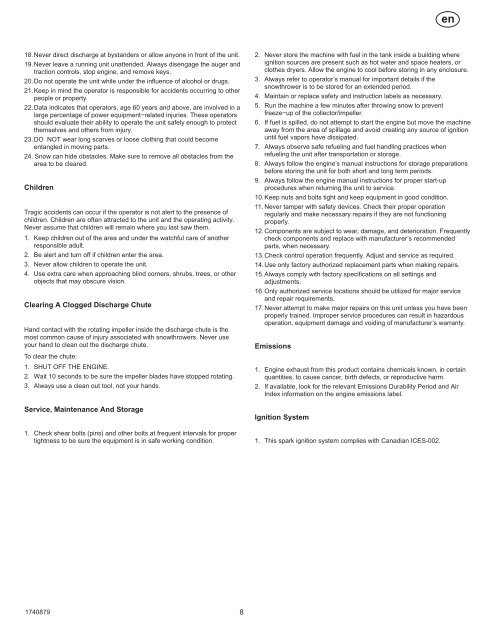
ASSEMBLYRead and follow the assembly and adjustmentinstructions for your snow thrower. All fastenersare in the parts bag. Do not discard any parts ormaterial until the unit is assembled.WARNING: Before doing anyassembly or maintenance to thesnow thrower, remove the wirefrom the spark plug.NOTE: In this instruction book, left and rightdescribe the location of a part from theoperator’s position behind the unit.NOTE: Torque is measured in foot pounds(metric N.m). This measurement describeshow tight a nut or bolt must be. The torque ismeasured with a torque wrench.NOTE: Fasteners and loose parts are shownat full size in Figure 2 on page 171.NOTE: Illustrations are located on page 2and on pages 172 through 177.Tools Required1 Knife1 Pliers2 1/2 inch open end wrenches2 9/16 inch open end wrenches2 3/4 inch open end wrenches1 Measuring tape or ruler1 ScrewdriverHow To Remove The <strong>Snow</strong> <strong>Thrower</strong>From The Carton1. (Figure 3) The snow thrower is shown in theshipping position.2. Cut down all four corners of the carton andlay the side panels flat or use pull tab toremove box from base.3. Cut and discard the plastic ties that securethe crank assembly and the speed controlrod assembly.4. Locate all parts that are packed separatelyand remove from the carton.5. Remove and discard the packing materialfrom around the snow thrower.6. (Figure 1) For shipping purposes, the heightadjust <strong>sk</strong>ids (7) are attached to the pallet.Remove the screw (17) that secures eachheight adjust <strong>sk</strong>id (7) to the pallet.7. Hold onto the lower handle and pull the snowthrower off the pallet.CAUTION: DO NOT back over cables.8. Remove the packing material from thehandle assembly.9. Cut the ties that secure the clutch controlcables (1) to the lower handle (2). Move thecables away from the motor frame.How To Assemble The Handle AndCrank Assembly1. (Figure 4) Loosen, but do not remove, thefasteners (1) in the upper holes of the lowerhandle.2. Remove the fasteners and the crankassembly eyebolt (11) from the lower holesof the lower handle.17408793. (Figure 1) Put the shift lever (6) into firstforward position.4. (Figure 4) Raise the upper handle (2) to theoperating position.NOTE: Make sure the cables are notcaught between the upper and lowerhandle.5. Install the fasteners and the crank assemblyeyebolt (11) that were removed in step 2.DO NOT tighten until all fasteners are inplace.6. (Figure 6) Attach the crank rod (15) to theuniversal joint assembly (16) with the hairpin (12).7. (Figure 4) Tighten nut on eye bolt (11).Make sure eye bolt (11) is properly alignedand the crank (18) can freely rotate.8. Tighten all handle fasteners.How To Install The KnobsNOTE: If knobs are already installed, go tothe next selection.Remote Chute Knob (Figure 10)1. Assemble remote chute knob (1) onto lever(3) until snug against nut (2). On somemodels the remote chute knob (1) isattached.2. Make sure lip (4) on the remote chute knob(1) is pointed toward the engine.3. Tighten the nut (2) against the bottom of theremote chute knob (1).Speed Select Knob(Figure 10) Install the speed select knob (11)to the speed select lever (1). On some modelsthe speed select knob (11) is attached.How To Install The Speed Control Rod1. (Figure 9) Attach the ball joint (6), locatedon the bottom end of the speed control rod(2), to the shift yoke assembly (7). Thefasteners (8) are attached to the ball joint(6) at the factory.The length of the ball joint (6) and speedcontrol rod (2) have been pre−adjusted atthe factory. If an adjustment is required,loosen the nut (9). Remove the fasteners(8) to disconnect the ball joint (6) from theshift yoke assembly (7). To lengthen orshorten the speed control rod (2), turn theadapter (10) to obtain the correct length.2. (Figure 10) Attach the handle (11) onto thespeed select lever (5). On some models thehandle (11) is attached. To lock in position,tighten the hex jam nut (10) against thebottom of the handle (11).3. Make sure the speed select lever (5)functions correctly. Move the speed selectlever (5) through all speeds.How To Assemble The Chute Deflector1. (Figure 7) Remove carriage bolt (1).2. Raise the chute deflector (2) into operatingposition (3).3. Fasten chute deflector (2) to flange (4) withcarriage bolts (1). Make sure to install withhead of the carriage bolts (1) on the insideof the flange (2).9en4. Fasten with washers (5) and locknuts (6).5. Tighten locknuts (6) securely.NOTE: Make sure all carriage bolts in flangeare tight. DO NOT OVERTIGHTEN.Check The Cables1. (Figure 8) Check the traction drive cable(1) and the auger drive cable (2). If thebottom of the cables have becomedisconnected, reinstall the cables.2. (Figure 11) If the top of the cables (5)have become disconnected from the drivelevers (6), attach the cables (5) to the “Z”fitting (7).How To Set The Skid Height (Figure 1)The snow thrower is equipped with heightadjustable <strong>sk</strong>ids (7) mounted on the outside ofthe auger housing (4). To adjust the height ofthe <strong>sk</strong>ids, see “How To Adjust The Height OfThe Skids” in the Maintenance section.How To Set The Length Of The CablesThe cables were adjusted at the factory and noadjustments should be necessary. However,after the handles are put in the operatingposition, the cables can be too tight or too loose.If an adjustment is necessary, see “How ToCheck And Adjust The Cables” in the ServiceAnd Adjustment section.How To Assemble The Drift Cutter(if equipped)Drift cutters are used to cut a path through snowdeeper than the auger housing.1. (Figure 12) Loosen the fasteners (2) thatsecure the drift cutters (1) to the augerhousing.2. Raise the drift cutters (1) to the desiredheight.3. Tighten the fasteners (2).How To Prepare The EngineNOTE: The engine was shipped from thefactory filled with oil. Check the level of theoil. Add oil as needed.WARNING: Follow the enginemanufacturer’s instructions for thetype of fuel and oil to use. Alwaysuse a safety fuel container. Do not smokewhen adding gasoline to the engine. Wheninside an enclosure, do not fill withgasoline. Before you add fuel, stop theengine. Let the engine cool for severalminutes.Check the oil. See the engine manufacturer’sinstructions for the type of fuel and oil to use.Before you use the unit, read the information onsafety, operation, maintenance, and storage.Important! Before You Start OperatingCheck the fasteners. Make sure allfasteners are tight.On electric start models, the unit wasshipped with the starter cord pluggedinto the engine. Before operating,unplug the starter cord from the engine.
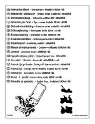
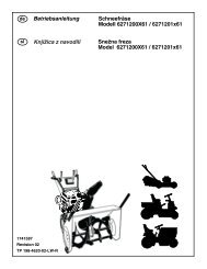
- Page 1 and 2: en Instruction Book Snow ThrowerMod
- Page 3 and 4: CONTENTSHAZARD SYMBOLS AND THEIR ME
- Page 5 and 6: en •
- Page 7: enRULES FOR SAFE OPERATIONWARNING:
- Page 11 and 12: WARNING: Never run the engineindoor
- Page 13 and 14: 5. Pull the cable (6) back through
- Page 15 and 16: How To Order Replacement PartsThe r
- Page 17 and 18: fr
- Page 19 and 20: fr •
- Page 21 and 22: 16.Ne touchez jamais à un moteur c
- Page 23 and 24: Vérifier le niveau d’huile. Voir
- Page 25 and 26: frTABLEAU DE MAINTENANCERESPONSABIL
- Page 27 and 28: 4. Resserrer les écrous (2).5. (Fi
- Page 29 and 30: Commande de pièces détachéesLe r
- Page 31 and 32: de
- Page 33 and 34: de •
- Page 35 and 36: de15.Betreiben Sie die Schneefräse
- Page 37 and 38: WARNUNG: Verwenden Sie nur dieBenzi
- Page 39 and 40: deWARTUNGSDIAGRAMMVERANTWORTUNGEN D
- Page 41 and 42: 3. (Abb. 19) Lösen Sie die Mutter
- Page 43 and 44: Bitte kontaktieren Sie Ihren lokale
- Page 45 and 46: it
- Page 47 and 48: it •
- Page 49 and 50: it13.Staccare l’alimentazione al
- Page 51 and 52: Vedere le istruzioni del produttore
- Page 53 and 54: itTABELLA DI MANUTENZIONERESPONSABI
- Page 55 and 56: 4. Serrare il dado (2).5. (Figura 2
- Page 57 and 58: Ordinazione di parti di ricambioLe
- Page 59 and 60:
no
- Page 61 and 62:
no •
- Page 63 and 64:
no19.La aldri en maskin som er i ga
- Page 65 and 66:
Viktig! Før du starter:Kontroller
- Page 67 and 68:
VEDLIKEHOLDBEMERK: Illustrasjonene
- Page 69 and 70:
5. Dersom en justering er nødvendi
- Page 71 and 72:
INNEHÅLLVARNINGSSYMBOLER OCH FÖRK
- Page 73 and 74:
sv •
- Page 75 and 76:
svREGLER FÖR SÄKERT HANDHAVANDEVA
- Page 77 and 78:
MONTERINGLäs och följ instruktion
- Page 79 and 80:
VARNING: Kör aldrig motorninomhus
- Page 81 and 82:
5. Dra kabeln (6) tillbaka genom fj
- Page 83 and 84:
FELSÖKNINGSSCHEMAPROBLEM ORSAK ÅT
- Page 85 and 86:
fi
- Page 87 and 88:
fi •
- Page 89 and 90:
fi18.Älä koskaan suuntaa lumisuih
- Page 91 and 92:
Poistettavan lumen ohjaaminen174087
- Page 93 and 94:
HUOLTOHUOMAA: Kuvat ovat sivulla 2
- Page 95 and 96:
2. Irrota sytytystulpan johto.3. (K
- Page 97 and 98:
SPIS TREŚCISYMBOLE OSTRZEGAWCZE I
- Page 99 and 100:
plNIEBEZPIECZEŃSTWONie dopuścić,
- Page 101 and 102:
plZASADY DOTYCZĄCE BEZPIECZNEJ OBS
- Page 103 and 104:
MONTAŻProsimy zapoznać się z ins
- Page 105 and 106:
Rozruch zimnego silnika (Rysunek 1)
- Page 107 and 108:
3. (Rysunek 22) Poluzować śruby (
- Page 109 and 110:
2. Odłączyć przewód świecy zap
- Page 111 and 112:
TURINYSPAVOJAUS SIMBOLIAI IR JŲ RE
- Page 113 and 114:
ltPAVOJUSBūkite atsargus - besisuk
- Page 115 and 116:
ltSAUGAUS EKSPLOATAVIMO TAISYKLĖS
- Page 117 and 118:
SURINKIMASPerskaitykite ir laikykit
- Page 119 and 120:
9. Paspauskite degalų purkštuko m
- Page 121 and 122:
Netepamos dalys (15 pav.)1. Netepki
- Page 123 and 124:
2. Atjunkite uždegimo žvakės lai
- Page 125 and 126:
TARTALOMVESZÉLYJELZŐ SZIMBÓLUMOK
- Page 127 and 128:
huVESZÉLYA forgó csiga súlyos, s
- Page 129 and 130:
huA BIZTONSÁGOS ÜZEMELTETÉS SZAB
- Page 131 and 132:
ÖSSZESZERELÉSOlvassa el és tarts
- Page 133 and 134:
12.Ha a motor 5-6 kísérlet után
- Page 135 and 136:
2. Ha a zsír vagy olaj a hajtótá
- Page 137 and 138:
15.(29 ábra) Szerelje vissza a job
- Page 139 and 140:
sk
- Page 141 and 142:
sk •
- Page 143 and 144:
sk
- Page 145 and 146:
VAROVANIE: Káble NEOHBAJTE.
- Page 147 and 148:
° °
- Page 149 and 150:
1740879
- Page 151 and 152:
sk
- Page 153 and 154:
СОДЕРЖАНИЕОБОЗНАЧ
- Page 155 and 156:
Эксплутационные об
- Page 157 and 158:
uПРЕДУПРЕЖДЕНИЕДви
- Page 159 and 160:
u4. В случае значите
- Page 161 and 162:
СБОРКАПрочитайте и
- Page 163 and 164:
ПРИМЕЧАНИЕ: Блок эл
- Page 165 and 166:
Все корректировки
- Page 167 and 168:
Как снять ремень фр
- Page 169 and 170:
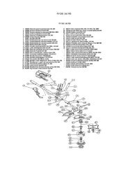
СХЕМА С УКАЗАНИЕМ М
- Page 171 and 172:
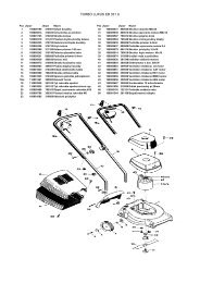
22− 95242− 39432 − 7382621740
- Page 173 and 174:
128927910681011141052311 1217625174
- Page 175 and 176:
18151391912103421716131411811202124
- Page 177:
2829111111223101530 311116716714178