SISTEMA DI LUBRIFICAZIONE CENTRALIZZATA - Vanax
SISTEMA DI LUBRIFICAZIONE CENTRALIZZATA - Vanax
SISTEMA DI LUBRIFICAZIONE CENTRALIZZATA - Vanax
- No tags were found...

You also want an ePaper? Increase the reach of your titles
YUMPU automatically turns print PDFs into web optimized ePapers that Google loves.
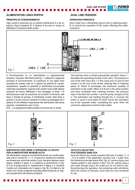
DUAL LINE SYSTEMALIMENTATORI LINEA DOPPIAPRINCIPIO <strong>DI</strong> FUNZIONAMENTOOgni uscita è asservita da un pistone distributore A e da unpistone Spool dosatore B. Il pistone A ha solo lo scopo dieffettuare l’inversione delle uscite.DUAL LINE FEEDERSOPERATING PRINCIPLEEach outlet has a distributing spool A and a metering pistonB. A controls the operation of the outlet, effecting the outletinversions.Fig. 1Il funzionamento di un alimentatore è rigorosamenteidraulico. Facendo riferimento alla fig. 1, abbiamo il seguenteprincipio di funzionamento: la pressione di una delle lineeprincipali (in questo caso la 1) agisce sul pistone B il quale,spostandosi, espelle la quantità di lubrificante accumulatanella fase precedente. Quando tutti i pistoni sono nelle stesseposizioni ed hanno effettuato il loro dosaggio, la linea 1 dialimentazione sale di pressione ed avviene l’inversione allalinea 2 tramite la pompa. Il lubrificante inviato nella linea 2sposta in modo inverso il pistone A e libera il passaggio per ilpistone B che effettua l’espulsione del lubrificante nell’uscitaopposta, completando così il ciclo.N.B. - La regolazione della portata è comune per 2 uscite.The dual line valve is strictly hydraulically operated. Figure 1 -Illustrates the operating principle of the valve. The pressure inone of the main lines (line 1 in this case) acts on spool A andmoves it to the end of the stroke, allowing flow to meteringpiston B. Piston B discharges the measured quantity oflubrication to the outlet. When A & B are in the same positionand have completed their metering function, the pressurerises in the feed line number 1 and the pump changes to line2. The lubrication now feeding through line 2, reverses theaction in spool A and piston B which forces the lubricationout of the opposite outlet, completing the cycle. Note: thevolumetric adjustment controls both outlets.Fig. 2 Fig. 3<strong>DI</strong>SPOSITIVO PER UNIRE O SEPARARE LE USCITEPER ALIMENTATORE MONOBLOCCOGli alimentatori vengono normalmente forniti con uscite separatecioè in numero di - 2 - 4 - 6 oppure 8. Qualora la richiestasia diversa per unire due uscite in una, bisogna operare comesegue: togliere il tappo a e sostituire la guarnizione b (fig.A) con la guarnizione d, riposizionare il tappo a e chiuderel’uscita non utilizzabile con il tappo e (fig. B). Si otterrà in talmodo che l’uscita erogherà la portata determinata da un doppiospostamento del pistone dosatore.OUTLETS SELECTIONFOR FEEDERS ENBLOCKDual line blocks are usually supplied with pair of outlets, 2 - 4- 6 or 8 outlets. If the application requires only 1 outlet, thenthe following must take place (Ref. Fig. A): remove plug a andreplace gasket b with gasket d (Ref. Fig. B), replace plug aand close through plug e the outlet you do not want to use.By performing this operation, the remaining outlet will delivertwice the volume of lubricant, since both are now connectedto one.