SISTEMA DI LUBRIFICAZIONE CENTRALIZZATA - Vanax
SISTEMA DI LUBRIFICAZIONE CENTRALIZZATA - Vanax
SISTEMA DI LUBRIFICAZIONE CENTRALIZZATA - Vanax
- No tags were found...
You also want an ePaper? Increase the reach of your titles
YUMPU automatically turns print PDFs into web optimized ePapers that Google loves.
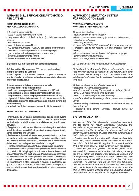
DUAL LINE SYSTEMIMPIANTO <strong>DI</strong> <strong>LUBRIFICAZIONE</strong> AUTOMATICOPER CATENECOMPONENTI NECESSARIPER REALIZZARE L’IMPIANTO1) Centralina comprendente:- vasca in acciaio con capacità di 60 litri;- segnalatore elettrico di livello minimo (contatto normalmentechiuso);- indicatore di livello visivo;- tappo di riempimento con filtro;- n. 2 pompe pneumatiche “FLENCO” con portata 4 cm 3 /impulso;- manometro per lettura pressione in uscita dalle pompe;- gruppo trattamento aria compressa con manometro;- elettrovalvola azionamento pompe;- valvola a scarico rapido;il tutto assiemato.2) Dosatore 100 mm 3 (uno per ogni punto da lubrificare).3) Tubo capillare Ø 4 lunghezza 500 mm con ugello calibrato(uno per ogni punto da lubrificare).Il tubo capillare dovrà essere modellato inopera in modo daorientare l’ugello verso il punto sul quale occorre proiettare la goccia(cuscinetto, snodo, ecc.).4) Apparecchiatura elettrica di comando e controllo(secondo norme FIAT) comprendente:- trasformatore con primario 500 volt e secondario 110 volt;- temporizzatore 0-24 ore per programmazione tempo ciclo;- temporizzatore 0-24 ore per programmazione tempo pausa;- dispositivi d’interfaccia tra sensore di posizione ed elettrovalvola;- segnalatore di allarme (Rotallarm) asservito al livello minimo olionella centralina;- spie luminose di funzionamento e controllo; il tutto assiemato.INSTALLAZIONE DELL’IMPIANTO- Individuare, su un passo qualsiasi della catena, dopo avernearrestato il movimento, i punti che richiedono lubrificazione.(Abitualmente, la lubrificazione viene effettuata su un solo passoper volta).- Scegliere una posizione in cui la catena sia ben guidata ed abbiaquindi le minime possibilità di spostarsi trasversalmente (sia insenso orizzontale che verticale).- Posizionare e fissare il primo dosatore, con relativo tubo capillareed ugello, in modo che l’ugello si trovi il più vicino possibile al puntoda lubrificare. Durante questa fase, accertarsi che lo sbandamentodella catena non porti questa ad interferire con l’ugello.- Ripetere l’operazione precedente per tutti i punti da lubrificare.- In corrispondenza del passo catena precedente a quello sul qualesono stati indirizzati gli ugelli, posizionare e fissare il sensore diprossimità in modo che risulti azionato. (Anche in questo caso tenerconto dello sbandamento che può subire la catena). La centralinanon dovrà essere ad oltre 18 metri di distanza dalla zona lubrificata.Se l’installazione è stata compiuta a dovere, in particolare, perquanto concerne il sensore di prossimità, attivando l’impianto siotterrà la lubrificazione di tutti i punti prestabiliti, su tutta la lunghezzadella catena.AUTOMATIC LUBRICATION SYSTEMFOR PRODUCTION LINESNECESSARY COMPONENTSFOR THE SYSTEM REALISATION1) Gearbox including:- steel bath with 60 litres capacity;- electric minimum level warning (contact normally closed);- visual level indicator;- filler plug with filter;- 2 pneumatic “FLENCO” pumps with 4 cm 3 / impulse output;- pressure gauge for reading the exit pressure from thepumps;- Compressed air treatment group with pressure gauge;- pump start up solenoid valve;- rapid discharge valve;all assembled.2) 100 mm 3 meter (one for each point to be lubricated).3) Capillary tube Ø 4 length 500 mm with calibrated nozzle(one for each point to be lubricated).The capillary tube mustbe modelled insuch a way to direct the nozzle towards thepoint on which the drop isto be projected (bearing, articulatedjoint etc.).4) Command and control electric equipment(according to FIATnorms) including:- transformer with primary 500 volt and secondary 110 volt;- timer 0-24 hours for cycle time planning;- timer 0-24 hours for pause time planning;- interface devices between position sensor and solenoidvalve;- alarm warning (Rotallarm) connected to minimum oil level inthe central part;- operation and control luminous warning lights; allassembled.SYSTEM INSTALLATION- On any part of the chain after having stopped the movement,find the points that require lubrication. (Habitually, thelubrication takes place on only one part at a time).- Choose a position in which the chain is well led andtherefore hasthe minimum chances of shifting sideways (bothhorizontally and vertically).- Position and fix the first meter, with relative capillary tubeand nozzle, in order that the nozzle is as close as possible tothe point to be lubricated. During this phase, check that theshift of the chain does not make it interfere with the nozzle.- Repeat the previous operation for all the points to belubricated. In correspondence to the chain pitch precedingthe one on which the nozzles were addressed, position andfix the proximity sensor so that it activates. (Also in this casetake into account the shift movement that the chain mayundergo). The gearbox must not be more that 18 metresfrom the lubricated area. If the installation has been carriedout correctly, in particular regarding the proximity sensor, thestart up of the system will bring about the lubrication of all thepreestablished points over the whole length of the chain.43


